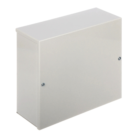
Pulsar AWO 232 User manual

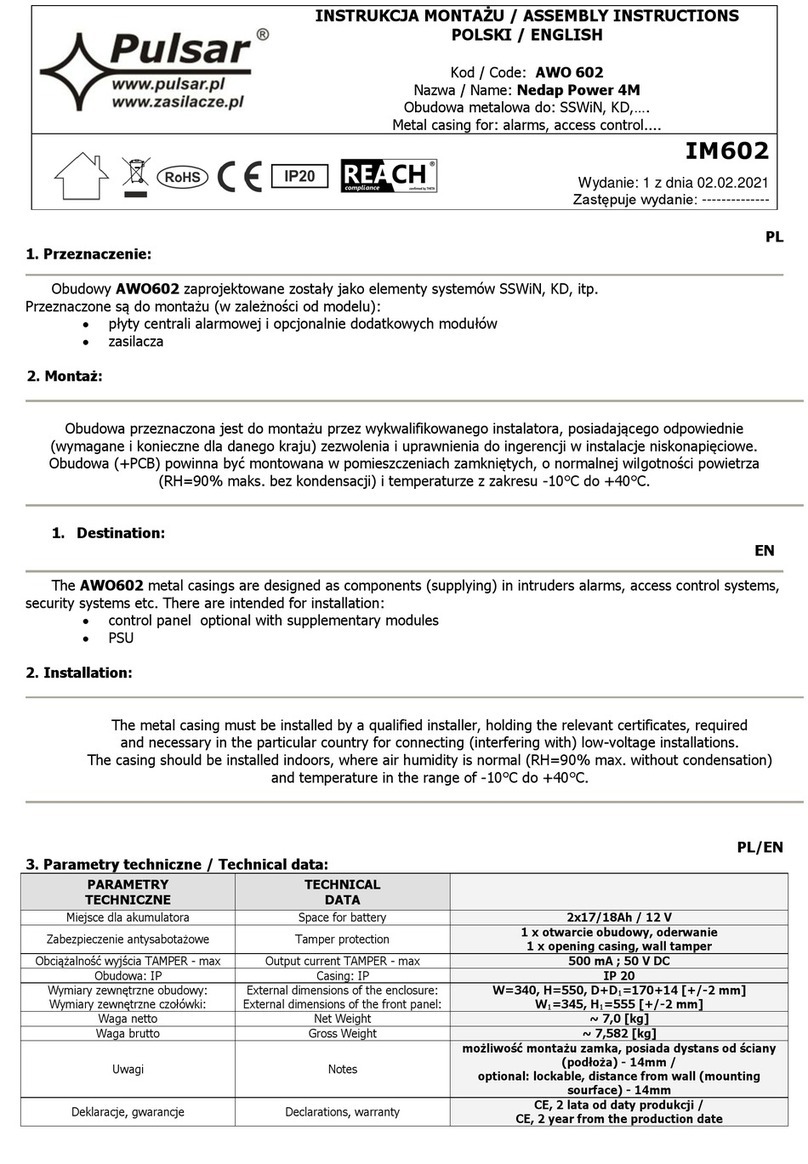
INSTRUKCJA MONTAŻU/ASSEMBLY INSTRUCTIONS
POLSKI/ENGLISH
Kod / code: AWO 232
Nazwa/ Name: 7/TRP40/PAR/L
Obudowa metalowa do: SSWiN, KD,….
Metal casing for: alarms, access control....
IM232
W danie: 2 z dnia 20.09.2017
Zastępuje w danie: 1 z dnia 12.01.2012
PL
1. Pr e nac enie:
Obudow AWO 232 zaprojektowane został jako element s stemów SSWiN, KD, itp.
Przeznaczone są do montażu (w zależności od modelu):
•pł t centrali alarmowej i opcjonalnie dodatkow ch modułów
•kontrolera s stemu KD i modułów dodatkow ch
•nadajnika radiowego lub GSM, opcjonalnie modułu zasilacza buforowego
•inn ch ded kowan ch urządzeń
2. Montaż:
Obudowa (+ PCB) przeznaczona jest do montażu przez w kwalifikowanego instalatora, posiadającego
odpowiednie ( w magane i konieczne dla danego kraju) zezwolenia i uprawnienia do prz łączania ( ingerencji)
w instalacje 230V/AC oraz instalacje niskonapięciowe.
Ponieważ transformator zaprojektowan jest do prac ciągłej nie posiada w łącznika zasilania, dlatego należ
zapewnić właściwą ochronę przeciążeniową w obwodzie zasilając m. Należ także poinformować uż tkownika o sposobie
odłączenia zasilacza od napięcia sieciowego (najczęściej poprzez w dzielenie i oznaczenie odpowiedniego bezpiecznika w
skrz nce bezpiecznikowej). Instalacja elektr czna powinna b ć w konana według obowiązując ch norm i przepisów.
Obudowa (+PCB) powinna b ć montowana w pomieszczeniach zamknięt ch, o normalnej wilgotności powietrza
(RH=90% maks. bez kondensacji) i temperaturze z zakresu -10°C do +40°C.
Pr ed pr ystąpieniem do instalacji należy upewnić się, że napięcie w obwod ie asilającym
230V/AC jest odłąc one.
Ws elkie prace serwisowe wewnątr obudowy należy wykonywac pr y odłąc onym
asilaniu 230V/AC
1. Zamontować w obudowie PCB w odpowiednich otworach montażow ch ( z uż ciem kołków d stansow ch, wkrętów
montażow ch itp.).
2. Zamontować obudowę w ded kowan m miejscu i doprowadzić przewod połączeniowe (~230V) i s gnałowe poprzez
przepust kablowe.
Uwagi: obwód zasilania ~230V należ w konać przewodem trójż łow m
(z żółto-zielon m przewodem ochronn m PE).
3. Przewod zasilania ~230V podłącz ć do zacisków 230V /AC L-N transformatora.
Przewód ochron przeciwporażeniowej PE podłącz ć do zacisku oznaczonego s mbolem uziemienia.
Praca asilac a be poprawnie wykonanego i sprawnego technic nie obwodu ochrony
pr eciwporażeniowej jest NIEDOPUSZCZALNA!
Gro i to us kod eniem ur ąd eń, porażeniem prądem elektryc nym.
4. Podłącz ć w jście transformatora do zacisków (~AC) PCB, uż wając dołączon ch przewodów
Uwagi: podłącz ć w magane napięcie U1 lub U2 dla danego urządzenia.
5. W konać opcjonalnie pozostałe połączenia w magane dla danego t pu urządzenia/s stemu.
Uwagi: zgodnie z w maganiami i zaleceniami producenta.
6. Wykonać uruchomienie ( ałąc enie asilania ~230V, akumulatora), regulacje lub konfiguracje: godnie
procedurą producenta systemu
7. Po instalacji i uruchomieniu s stemu należ zamknąć obudowę
2
1. Destination: EN
The AWO 232 metal casings are designed as components (suppl ing) in intruders alarms, access control s stems,
securit s stems etc. There are intended for installation:
•control panel optional with supplementar modules
•access control controllers with optional modules
•radio or GSM transmitter with optional module PSU
•other dedicated devices, components etc.
2. Installation:
The metal casing (+PCB) must be installed b a qualified installer, holding the relevant certificates, required and
necessar in the particular countr for connecting (interfering with) the 230V AC s stems and low-voltage installations.
Because the transformer is designed for the continuous operation and is not equipped with ON/OFF switch, the
power suppl line should have the appropriate overload protection. The user should be informed how to disconnect the
unit from the mains (the most often b separate and mark the adequate fuse in the fuse box). The power suppl
installation should be conform to the applicable standards and law.
The casing (+PCB) should be installed indoors, where the air humidit is normal (RH=90% max. without
condensation) and temperature in the range of -10°C to +40°C.
Caution! Prior to entering for installation it is necessary to make sure if the voltage
in the 230 V/AC circuit is disconnected.
All service works inside the housing must be carried out with 230V/AC supply voltage
disconnected.
1. Mount the PCB (control panel, etc) with dedicated holes (use distance pins, bracket screw).
2. Install metal casing in dedicated place and bring in the connecting (~230V) and signal conductors through cables
bushings.
Remarks: suppl circuit ~230V should be carried out with three-core cable
(with ellow-green protective PE conductor).
3. Suppl conductors ~230V should be connected to 230V / AC L-N terminals of the transformers.
Protective conductor should be connected to the terminal marked with grounding s mbol.
Caution! Operating the power supply without properly made and technically
operational electric shock protection circuit is IMPERMISSIBLE!
This creates ha ard of equipment damage and risk of electric shock.
4. Connect the output of transformer to the terminals (~AC) on the PCB, using installed cables
Remarks: connect required voltage U1 or U2 (secondar voltage) for the correct device.
5. If necessar , make other connections required for the correct t pe of s stem / device.
Remarks: consistent with requirements and recommendation of the producer.
6. Start the system (switch on ~230V, battery), adjust or configure: according to procedure of the
producer’s system.
7. After installing and checking the proper operation of the s stem, close the casing.

3
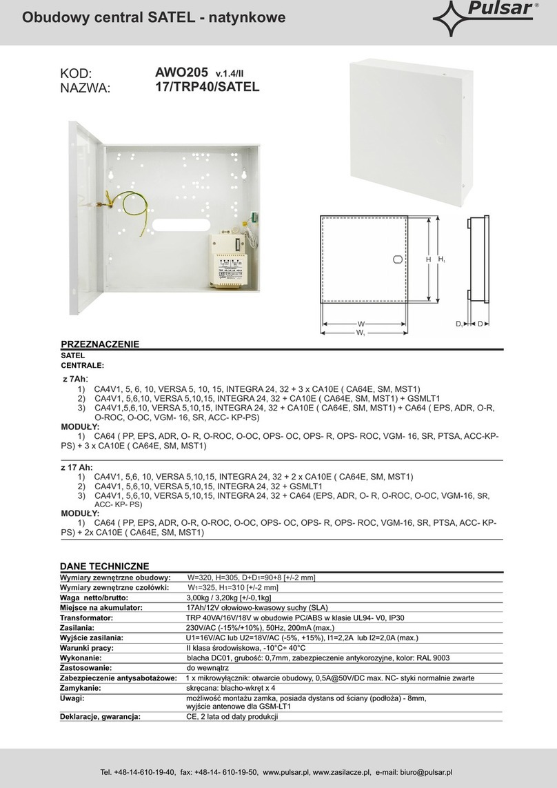
3. Parametry technic ne / Technical data:
PL/EN
PARAMETRY
TECHNICZNE
TECHNICAL
DATA
Napięcie zasilania
Power suppl voltage
230V/AC, 50H
(-/+15%)
Transformator Transformer TRP 40/16/18
Norma transformatora
T
ransformer
norm
EN 61558
-
2
-
6
Miejsce dla akumulatora
Space for b
atter
7Ah/12V
lub/or 17Ah/12V
Zabezpieczenie ant sabotażowe Tamper protection
1x
–
otwarcie obudowy
1x – opening casing
Obciążalność w jścia TAMPER
-
max
Output current TAMPER
-
max
500mA@
5
0V
DC
Obudowa: IP
Casing: IP
IP 20
Temperatura prac
Operating temperature
-
10ºC÷40
ºC
Wilgotność względna RH
–
max.
Relative
humidit RH
–
max.
90
[%]
W miar zewnętrzne obudow :
W miar zewnętrzne czołówki:
External dimensions of the enclosure:
External dimensions of the front panel:
W=320, H=305
, D+D
1
=9
0+8
[+/-2 mm]
W
1
=325, H
1
=310 [+/-2 mm]
W konanie Material description
Blacha DC01, grubość: 0,7mm
Zabe piec enie antykoro yjne
Kolor: RAL 9003/
Sheet steel DC01, Thickness: 0,7mm,
Protection anticorrosion,
Color: RAL9003
Zastosowanie
Destination
Do wewnątr
/Indoor
Waga netto
Net
Weight
~
3
.
30
[kg]
Waga brutto
Gross
W
eight
~
3
.
5
0
[kg]
Deklaracje, gwarancje Declarations, warrant
CE,
2 lata
od daty produkcji
/
CE, 2 year from the production date
Parametry technic ne
transformatora
: TRP
4
0/
16/18
Technical data of transformer: TRP 40/16/18
NAZWA
NAME C S U I U1 lub U2
or
I1 lub I2
or F t
TRP 40/16/18
PC/ABS
UL94 V-0
IP30
40VA 230V/AC 0,20A 16V lub 18V
or
2,2A lub 2,0A
or T 315mA/250V 130
o
C
C- Obudowa transformatora / Transformer casing
S - Moc / Power rating
U - Napięcie zasilania / Suppl voltage
I - Prąd pobieran prz nominaln m obciążeniu z sieci ~230V / Current draw at nominal load, from network ~230V
U1 lub/or U2 - Napięcia wtórne / Secondar voltage
I1 lub/or I2 - Nominaln prąd w jściow / Nominal output current
F – Bezpiecznik F w obwodzie pierwotn m transformatora / Fuse F in the primar windings of the transformer
t- Bezpiecznik termiczn 130
o
C niepowracaln / non ressetable fuse 130
o
C
4. Centrale które można amontować w tej obudowie / panels which can be mounted in the casing.
7Ah:
1) (728 ULT, E55, E65, SP4000, 5500, 6000, 7000, EV048, 192, MG5000, 5050, PS17, ACM12) + 2x ZX8 ( 4xZX4, APR3-
ADM2,APR3-HUB2, PGM4)
17Ah:
1) (728 ULT, E55, E65, SP4000, 5500, 6000, 7000, EV048, 192, MG5000, 5050, PS17, ACM12) + ZX4

4
PL/EN
OZNAKOWANIE WEEE
Zużytego spr ętu elektryc nego i elektronic nego nie wolno wyr ucać ra em e wykłymi domowymi odpadami.
Według dyrektywy WEEE obowią ującej w UE dla użytego spr ętu elektryc nego i elektronic nego należy stosować
odd ielne sposoby utyli acji.
W Polsce zgodnie z przepisami o zuż t m sprzęcie elektr czn m i elektroniczn m zabronione jest umieszczanie łącznie z inn mi
odpadami zuż tego sprzętu oznakowanego s mbolem przekreślonego kosza. Uż tkownik, któr zamierza się pozb ć tego produktu, jest
obowiązan do oddania ww. do punktu zbierania zuż tego sprzętu. Punkt zbierania prowadzone są m. in. przez sprzedawców hurtow ch i detaliczn ch
tego sprzętu oraz gminne jednostki organizac jne prowadzące działalność w zakresie odbierania odpadów. Prawidłowa realizacja t ch obowiązków ma
znaczenie zwłaszcza w prz padku, gd w zuż t m sprzęcie znajdują się składniki niebezpieczne, które mają negat wn wpł w na środowisko i zdrowie
ludzi.
WEEE MARK
The waste electric and electronic products do not mix with general household waste. There is separate collection system for used
electric and electronic products in accordance with legislation under the WEEE Directive and is effective only with EU.
Ogólne warunki gwarancji
Ogólne warunki gwarancji dostępne na stronie www.pulsar.pl
ZOBACZ
PRODUCENT / PRODUCER
Pulsar
Siedlec 150,
32-744 Łapczyca, Poland
Tel. (+48) 14-610-19-40, Fax. (+48) 14-610-19-50
e-mail: [email protected], [email protected]
http:// www.pulsar.pl, www.zasilacze.pl
Table of contents
Languages:
Other Pulsar Enclosure manuals

Pulsar
Pulsar 7/TRP20/GSM User manual

Pulsar
Pulsar ZRS2761GD User manual

Pulsar
Pulsar RS4281 User manual

Pulsar
Pulsar AWO 151 User manual

Pulsar
Pulsar AWO530 User manual

Pulsar
Pulsar 7/EI20/EBS/LX User manual

Pulsar
Pulsar ARADIN1 User manual

Pulsar
Pulsar AWO-256 User manual

Pulsar
Pulsar AWO 220K User manual

Pulsar
Pulsar ARAD2 User manual

Pulsar
Pulsar AWZ637 User manual

Pulsar
Pulsar AWO610 User manual

Pulsar
Pulsar AWO 359 User manual

Pulsar
Pulsar 17/TRP40/SATEL User manual

Pulsar
Pulsar AWO385 User manual

Pulsar
Pulsar AWO152PU User manual

Pulsar
Pulsar AWO352 User manual

Pulsar
Pulsar DIN1 User manual

Pulsar
Pulsar AWO529 User manual

Pulsar
Pulsar 17/TRP80/DSPR User manual