Pulsar AWO269PU User manual

INSTRUKCJA MONTAŻU/ASSEMBLY INSTRUCTIONS
POLSKI/ENGLISH
v1.1
Kod/Code: AWO269PU
Nazwa/Name: Obudowa 17/80/SATEL/PUSTA/GRADE3
Obudowa metalowa do: SSWiN, KD i podobnych.
Metal casing for: alarms, access control....
IM269PU
Wydanie/Edition: 3 z dnia/from 05.05.2023
Zastępuje wydanie/Supersedes edition: 2 z dnia/from 02.11.2017
PL
1. Przeznaczenie:
Obudowy AWO269PU spełniają normę PN-EN50131 Stopnia 3. Zaprojektowane zostały jako elementy systemów
SSWiN, KD, itp.
Przeznaczone są do montażu (w zależności od modelu):
płyty centrali alarmowej i opcjonalnie dodatkowych modułów
kontrolera systemu KD i modułów dodatkowych
nadajnika radiowego lub GSM, opcjonalnie modułu zasilacza buforowego
innych dedykowanych urządzeń
2. Montaż:
Obudowa (+ PCB) przeznaczona jest do montażu przez wykwalifikowanego instalatora, posiadającego
odpowiednie (wymagane i konieczne dla danego kraju) zezwolenia i uprawnienia do przyłączania (ingerencji)
w instalacje 230V/AC oraz instalacje niskonapięciowe.
Ponieważ transformator zaprojektowany jest do pracy ciągłej nie posiada wyłącznika zasilania, dlatego należy
zapewnić właściwą ochronę przeciążeniową w obwodzie zasilającym. Należy także poinformować użytkownika o sposobie
odłączenia zasilacza od napięcia sieciowego (najczęściej poprzez wydzielenie i oznaczenie odpowiedniego bezpiecznika w
skrzynce bezpiecznikowej). Instalacja elektryczna powinna być wykonana według obowiązujących norm i przepisów.
Obudowa (+PCB) powinna być montowana w pomieszczeniach zamkniętych, o normalnej wilgotności powietrza
(RH=90% maks. bez kondensacji) i temperaturze z zakresu -10°C do +40°C.
Przed przystąpieniem do instalacji należy upewnić się, że napięcie w obwodzie zasilającym
230V/AC jest odłączone.
Wszelkie prace serwisowe wewnątrz obudowy należy wykonywac przy odłączonym
zasilaniu 230V/AC
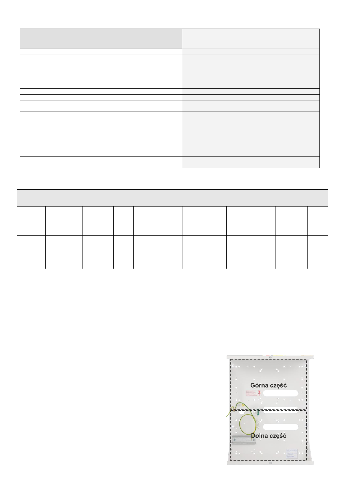
1. Zamontować w obudowie PCB w odpowiednich otworach montażowych (z użyciem kołków dystansowych, wkrętów
montażowych itp.).
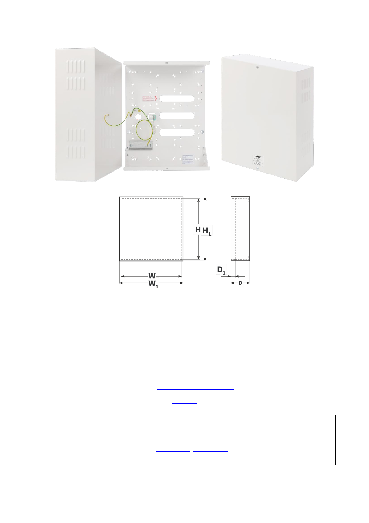
2. Zamontować obudowę w dedykowanym miejscu i doprowadzić przewody połączeniowe (~230 V) i sygnałowe poprzez
przepusty kablowe.
Uwagi: obwód zasilania ~230 V należy wykonać przewodem trójżyłowym
(z żółto-zielonym przewodem ochronnym PE).
3. Przewody zasilania ~230 V podłączyć do zacisków 230 V /AC L-N transformatora.
Przewód ochrony przeciwporażeniowej PE podłączyć do zacisku oznaczonego symbolem uziemienia .
Praca zasilacza bez poprawnie wykonanego i sprawnego technicznie obwodu ochrony
przeciwporażeniowej jest NIEDOPUSZCZALNA!
Grozi to uszkodzeniem urządzeń, porażeniem prądem elektrycznym.
4. Podłączyć wyjście transformatora do zacisków (~AC) PCB, używając dołączonych przewodów
Uwagi: podłączyć wymagane napięcie U1 lub U2 dla danego urządzenia.
5. Wykonać opcjonalnie pozostałe połączenia wymagane dla danego typu urządzenia/systemu.
Uwagi: zgodnie z wymaganiami i zaleceniami producenta.
6. Wykonać uruchomienie (załączenie zasilania ~230 V, akumulatora), regulacje lub konfiguracje: zgodnie
z procedurą producenta systemu
7. Po instalacji i uruchomieniu systemu należy zamknąć obudowę.

2
1. Destination: EN
AWO269PU metal casings compliant with EN50131 GRADE 3 are designed as components (supplying) in
intruders alarms, access control systems, security systems etc. There are intended for installation:
control panel optional with supplementary modules
access control controllers with optional modules
radio or GSM transmitter with optional module PSU
other dedicated devices, components etc.
2. Installation:
The metal casing (+PCB) must be installed by a qualified installer, holding the relevant certificates, required and
necessary in the particular country for connecting (interfering with) the 230 V AC systems and low-voltage installations.
Because the transformer is designed for the continuous operation and is not equipped with ON/OFF switch, the
power supply line should have the appropriate overload protection. The user should be informed how to disconnect the
unit from the mains (the most often by separate and mark the adequate fuse in the fuse box). The power supply
installation should be conform to the applicable standards and law.
The casing (+PCB) should be installed indoors, where the air humidity is normal (RH=90% max. without
condensation) and temperature in the range of -10°C to +40°C.
Caution! Prior to entering for installation it is necessary to make sure if the voltage
in the 230 V AC circuit is disconnected.
All service works inside the housing must be carried out with 230 V AC supply voltage
disconnected.
1. Mount the PCB (control panel, etc) with dedicated holes (use distance pins, bracket screw).
2. Install metal casing in dedicated place and bring in the connecting (~230 V) and signal conductors through cables
bushings.
Remarks: supply circuit ~230 V should be carried out with three-core cable
(with yellow-green protective PE conductor).
3. Supply conductors ~230 V should be connected to 230 V / AC L-N terminals of the transformers.
Protective conductor should be connected to the terminal marked with grounding symbol.
Caution! Operating the power supply without properly made and technically
operational electric shock protection circuit is IMPERMISSIBLE!
This creates hazard of equipment damage and risk of electric shock.
4. Connect the output of transformer to the terminals (~AC) on the PCB, using installed cables
Remarks: connect required voltage U1 or U2 (secondary voltage) for the correct device.
5. If necessary, make other connections required for the correct type of system / device.
Remarks: consistent with requirements and recommendation of the producer.
6. Start the system (switch on ~230 V, battery), adjust or configure: according to procedure of the
producer’s system.
7. After installing and checking the proper operation of the system, close the casing.

3
3. Parametry techniczne / Technical data: PL/EN
PARAMETRY
TECHNICZNE
TECHNICAL
DATA
Miejsce dla akumulatora
Space for battery
17Ah/12V
Zabezpieczenie antysabotażowe
Tamper protection
Obudowa wyposażona jest w zestaw zawierający
wspornik montażowy z tamperem / Enclosure is
equipped with set including mounting bracket with
tamper
Obciążalność wyjścia TAMPER –max
Output current TAMPER –max
500mA@50 V DC
Obudowa: IP
Casing: IP
IP 20
Temperatura pracy
Operating temperature
-10ºC ÷40ºC
Wilgotność względna RH – max.
Relative humidity RH –max.
90 [%]
Wymiary zewnętrzne obudowy
Wymiary zewnętrzne czołówki
External dimensions of enclosure
External dimensions of front panel
W=320, H =400, D=130, D1=15 [-/+2mm]
W1=326, H1=408 [+/- 2mm]
Wykonanie
Material description
Blacha DC01, grubość: 1,0mm, Zabezpieczenie
antykorozyjne
Kolor: RAL 9003/
Sheet steel DC01, Thickness: 1,0mm, Protection
anticorrosion,
Color: RAL9003
Zastosowanie
Destination
Do wewnątrz/Indoor
Waga netto/brutto
Weight Net/Gross
4,56 / 4,77 [kg]
Gwarancja
Warranty
2 lata od daty produkcji
2 years from production date
Tab1.
Parametry techniczne transformatorów, które można zamontować w obudowie:
KOD
CODE
NAZWA
NAME
C
S
U
I
U1 lub U2 lub U3
I1 lub I2 lub I3
F
t
AWT682
TRZ 60/18/20
PC/ABS UL 94
V-0, IP43
60VA
230 V AC
0,33A
18V lub 20V
18V or 20V
3,3A lub 3,0A
3,3A or 3,0A
T 500mA/250V
130oC
AWT8161820
TRZ 80/16/18/20
PC/ABS UL 94
V-0, IP43
80VA
230 V AC
0,4A
16V lub 18V lub 20V
16V or 18V or 20V
5,0A lub 4,5A lub 4,0A
5,0A or 4,5A or 4,0A
T 630mA/250V
130oC
AWT8172430
TRZ 80/17/24/30
PC/ABS UL 94
V-0, IP43
80VA
230 V AC
0,4A
17V lub 24V lub 30V
17V or 24V or 30V
4,5A lub 3,3A lub 2,7A
4,5A or 3,3A or 2,7A
T 630mA/250V
130oC
C - Obudowa transformatora / Transformer casing
S- Moc / Power rating
U- Napięcie zasilania / Supply voltage
I - Prąd pobierany przy nominalnym obciążeniu z sieci ~230 V / Current draw at nominal load, from network ~230 V
U1 lub/or U2 lub/or U3 - Napięcia wtórne / Secondary voltage
I1 lub/or I2 lub/or I3 - Nominalny prąd wyjściowy / Nominal output current
F–Bezpiecznik F w obwodzie pierwotnym transformatora / Fuse F in the primary windings of the transformer
t - Bezpiecznik termiczny 130oC niepowracalny / non ressetable fuse 130oC
4. Centrale i Moduły Satel, które można zamontować w tej obudowie / panels & modules Satel, which can
be mounted in the casing.
Część górna obudowy /
The upper part of the housing
1. INT-E x 6 szt./pcs. max
2. INT-PP x 3 szt./pcs. max
3. INT-IORS / INT-ORS x 2 szt./pcs. max
(po zastosowaniu zestawu szyny DIN AWO269S) /
(After using AWO269S din rail kit)
Część dolna obudowy / The lower part of the housing
1. INT-E x 6 szt./pcs. max
2. INT-PP x 3 szt./pcs. max
3. INT-IORS / INT-ORS x 2 szt./pcs. max
(po zastosowaniu zestawu szyny DIN AWO269S) /
(After using the AWO269S din rail kit)

4
4. Transformator i akumulator 7Ah / 17Ah / Transformer and Battery 7Ah / 17Ah
5. Zasilacz APS–612 lub APS–412 i akumulator 7Ah / 17Ah / Power supply unit APS–612 or APS–412 and Battery
7Ah / 17Ah
Ogólne warunki gwarancji
Ogólne warunki gwarancji dostępne na stronie www.pulsar.pl
ZOBACZ
PRODUCENT / PRODUCER
Pulsar
Siedlec 150, 32-744 Łapczyca, Poland
Tel. (+ 48) 14-610-19-40, Fax. (+ 48) 14-610-19-50
e-mail: biur[email protected], sales@pulsar.pl
http:// www.pulsar.pl, www.zasilacze.pl
Table of contents
Languages:
Other Pulsar Industrial Equipment manuals
Popular Industrial Equipment manuals by other brands

JJM Boiler Works
JJM Boiler Works CBM-226 Installation operation & maintenance

Siemens
Siemens HiPath 3000 operating instructions

MTE
MTE SineWave Guardian SWGM0002D Technical reference manual

V.ORLANDI
V.ORLANDI E 40 Technical description, installation, operating and maintenance instructions

gefran
gefran KH-SIL2 Series manual

Repar2
Repar2 TC 4 instruction manual