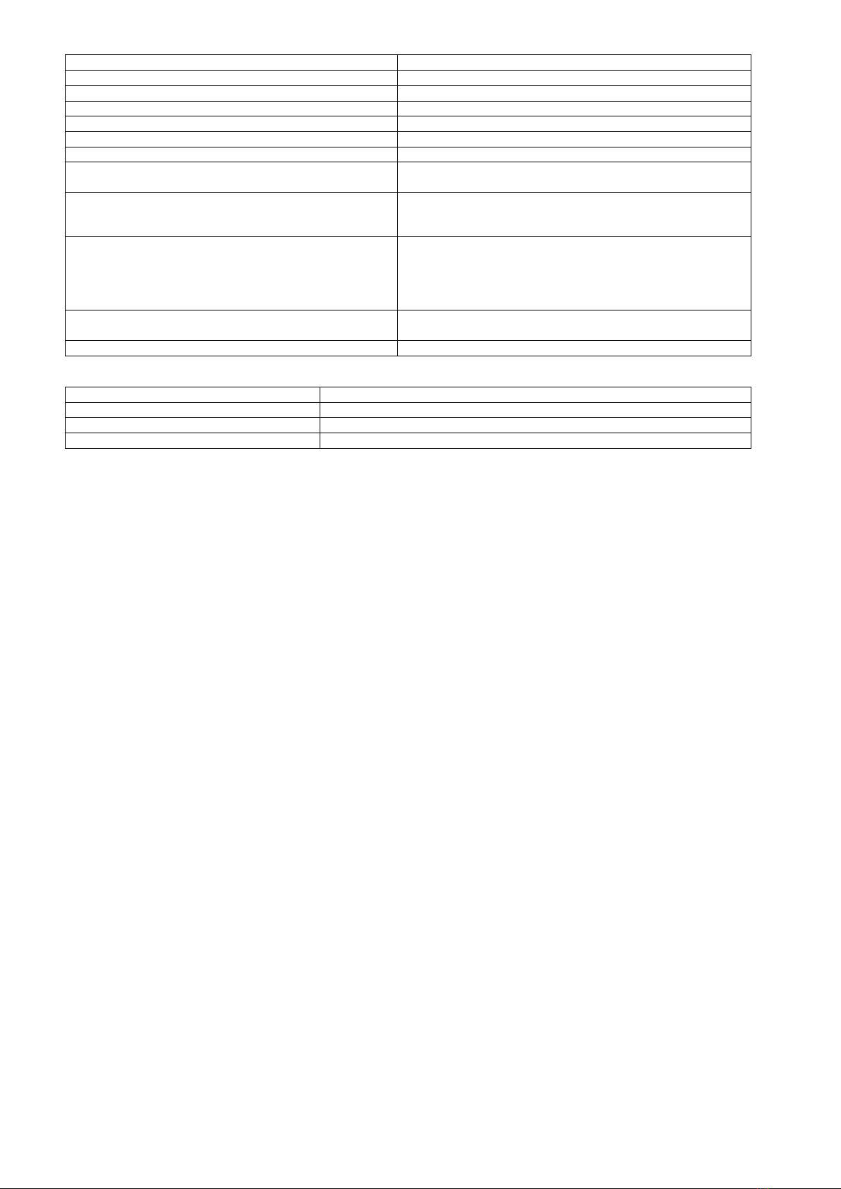
Table 3.
The input voltage range (power supply)
Current consumption by module systems
Short-circuit protection and overload OLP
110-150% of the module’s power, manual restart (the failure
requires disconnection of the DC output circuit)
Technical outputs
- PSU output indicating failure –overload or short-
circuit in the AUX output
- OC type, 50mA max. Failure status: hi-Z state (high
impedance), normal status: L level (0V)
Optical indication
- IN LED indicating DC power status
- AUX LED indicating DC supply status at the output
- PSU LED indicating failure - overload or short-
circuit in the AUX output
- red, normal status: is lit continuously
- green, normal status: is lit continuously
- red, normal status: does not lit, failure: is lit continuously
II environmental class, -10°C ÷40°C, ensure air flow around
the unit for convection cooling
CE, 2 years from the production date
Table 4.
tape or mounting screw x 2
2. Installation.
2.1. Requirements.
The DC/DC converter is to be mounted by a qualified installer, holding relevant permits and licenses (applicable and required
for a given country) for step up installations. The module should be mounted in confined spaces with normal relative humidity
(RH=90% maximum, no condensation) and temperature range from -10°C up to +40°C. The module should operate in vertical position
in order to provide free and convectional air flow.
The module's load balance should be done prior to installation. During normal operation, the total current of the receivers
should not exceed I=2,5A while the power drawn from the module should not exceed Pmax=120W.
Proper operation of the module requires adequate current capacity of the power source; the power supply capacity should be
calculated using the formula below: PIN = 1,15 x PAUX
(PIN = 1,15 x IAUX x UAUX)
Example:
The converter will supply the receivers with a capacity of PAUX = 96W drawing a total current of IAUX = 2A at the voltage
UAUX = 48V. The minimum power supply capacity must therefore amount to: PIN = 1,15 x 2A x 48V = 110,4W.
The device should be mounted in a metal enclosure (cabinet). The rules for power supply, enclosures and shielding - according to
application - must be observed in order to meet the requirements of LVD and EMC directives.
2.2. Installation procedure.
1. Mount the enclosure (cabinet, etc.) and lead cables through cable glands.
2. Mount the DC/DC converter with adhesive tape or mounting screws.
3. Supply DC voltage to the + IN, -IN terminals with correct polarization.
4. Connect the receivers’ cables to the +AUX, -AUX connectors of the terminal block on the module’s board.
5. Connect the device cables (alarm control panel, indicator, LED light, etc.) to the PSU technical output if necessary.
6. Switch on the DC voltage (the red IN LED should be permanently illuminated, the AUX green LED should be permanently
illuminated).
7. Once the tests and operation control are performed, close the enclosure, cabinet, etc.
3. Converter 's module operation indication.
3.1. Technical output.
The converter is equipped with three diodes indicating operation status: IN, AUX, and PSU.
IN- red LED: during normal status (DC power supply) it is lit continuously. No DC supply is indicated by switching off the IN LED.
AUX- green LED: indicates DC supply status at the module’s output. During normal status, it is lit continuously, in case of short
circuit or overload the AUX led is off.
PSU- red LED: indicates module’s overload. During normal status, it is off, in case of short circuit or overload the LED lights
continuously.