manuals.online logo
Brands
  1. Home
  2. •
  3. Brands
  4. •
  5. Pulsar
  6. •
  7. Media Converter
  8. •
  9. Pulsar DC/DC50SD User manual

Pulsar DC/DC50SD User manual

Other Pulsar Media Converter manuals

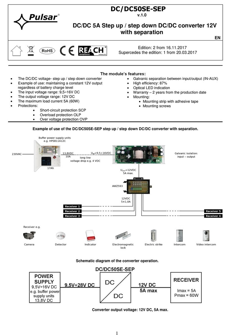
Pulsar DC/DC50SE-SEP User manual

Pulsar

Pulsar DC/DC50SE-SEP User manual

Pulsar DC/DC50HV User manual

Pulsar

Pulsar DC/DC50HV User manual

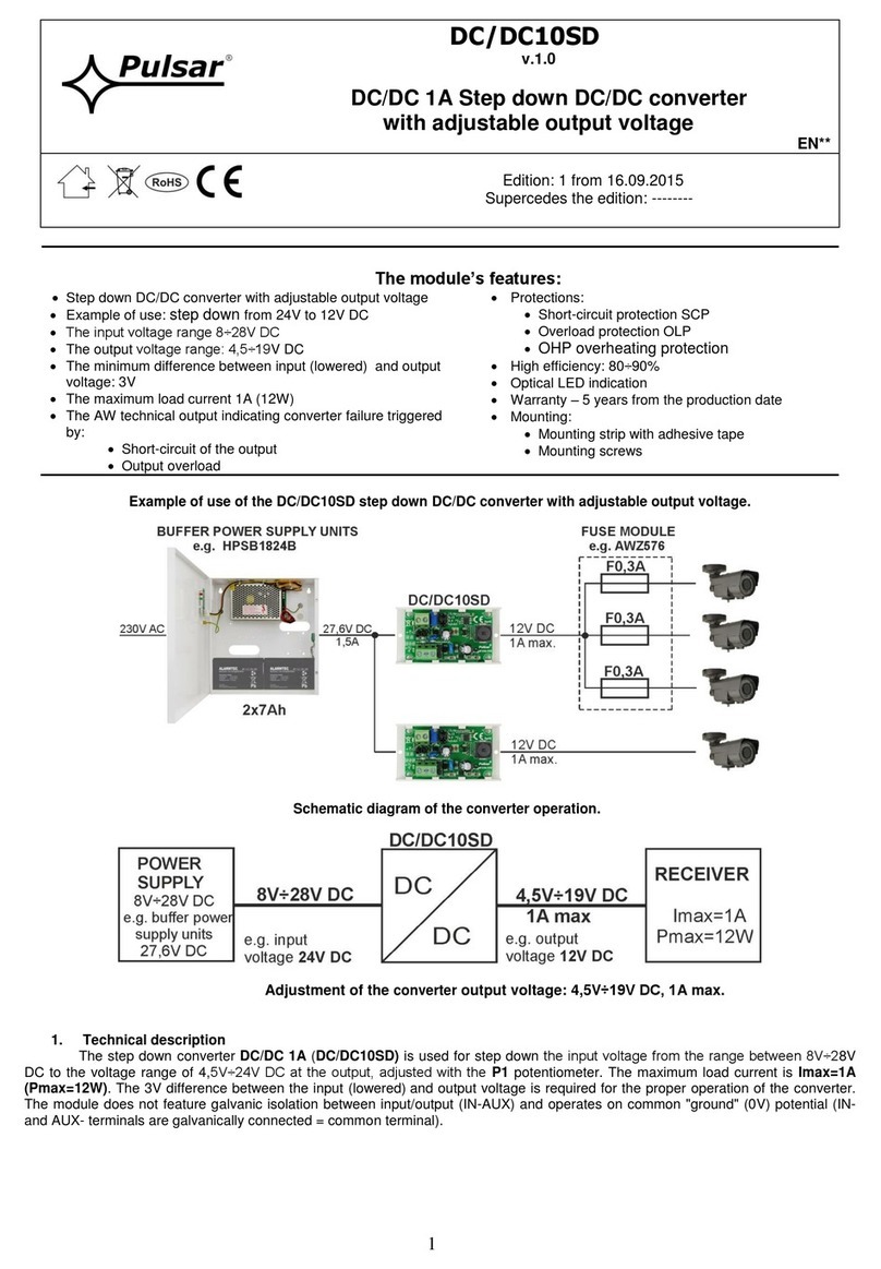
Pulsar DC/DC10SD User manual

Pulsar

Pulsar DC/DC10SD User manual

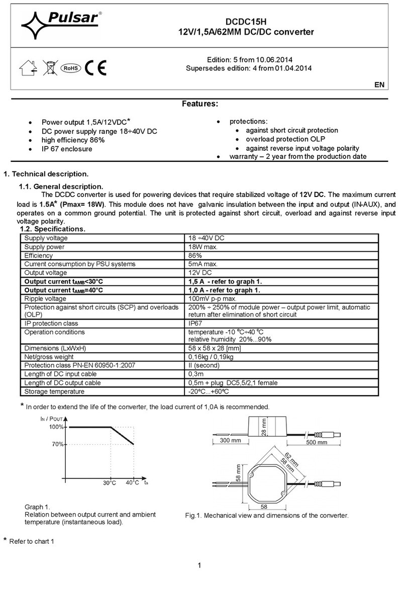
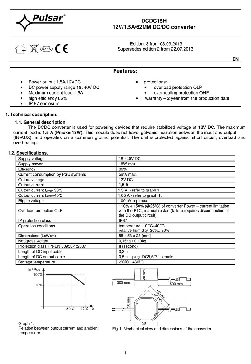
Pulsar DCDC15H User manual

Pulsar

Pulsar DCDC15H User manual

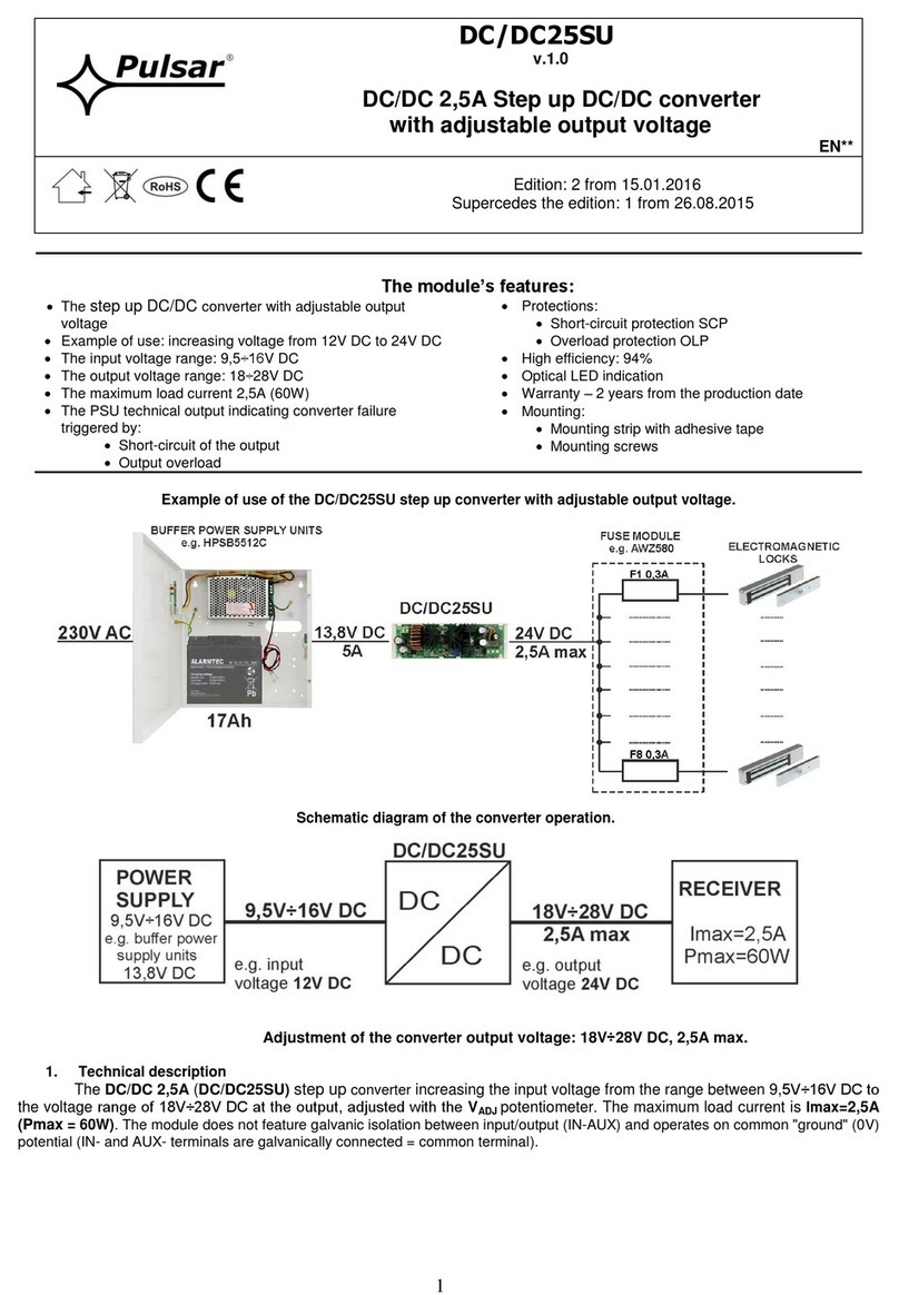
Pulsar DC/DC25SU User manual

Pulsar

Pulsar DC/DC25SU User manual

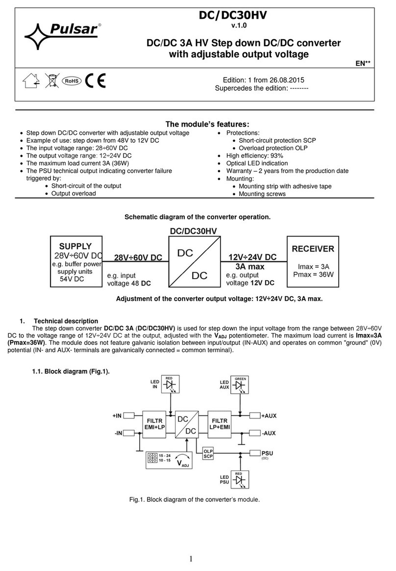
Pulsar DC/DC30HV User manual

Pulsar

Pulsar DC/DC30HV User manual

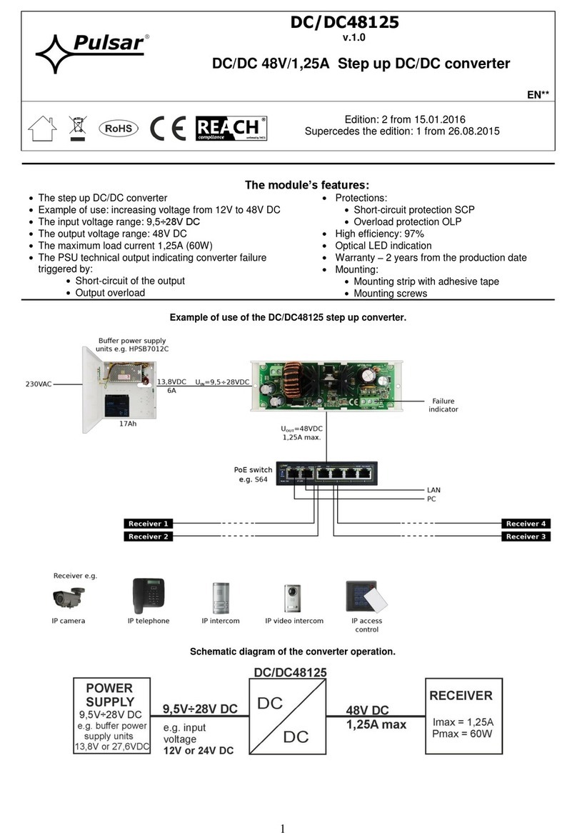
Pulsar DC/DC48125 User manual

Pulsar

Pulsar DC/DC48125 User manual

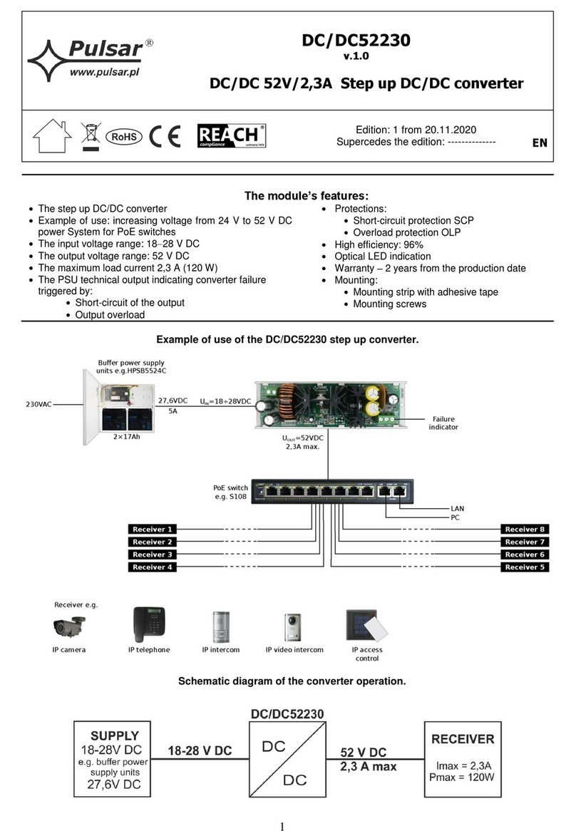
Pulsar DC/DC52230 User manual

Pulsar

Pulsar DC/DC52230 User manual

Pulsar HDMI-VGA User manual

Pulsar

Pulsar HDMI-VGA User manual

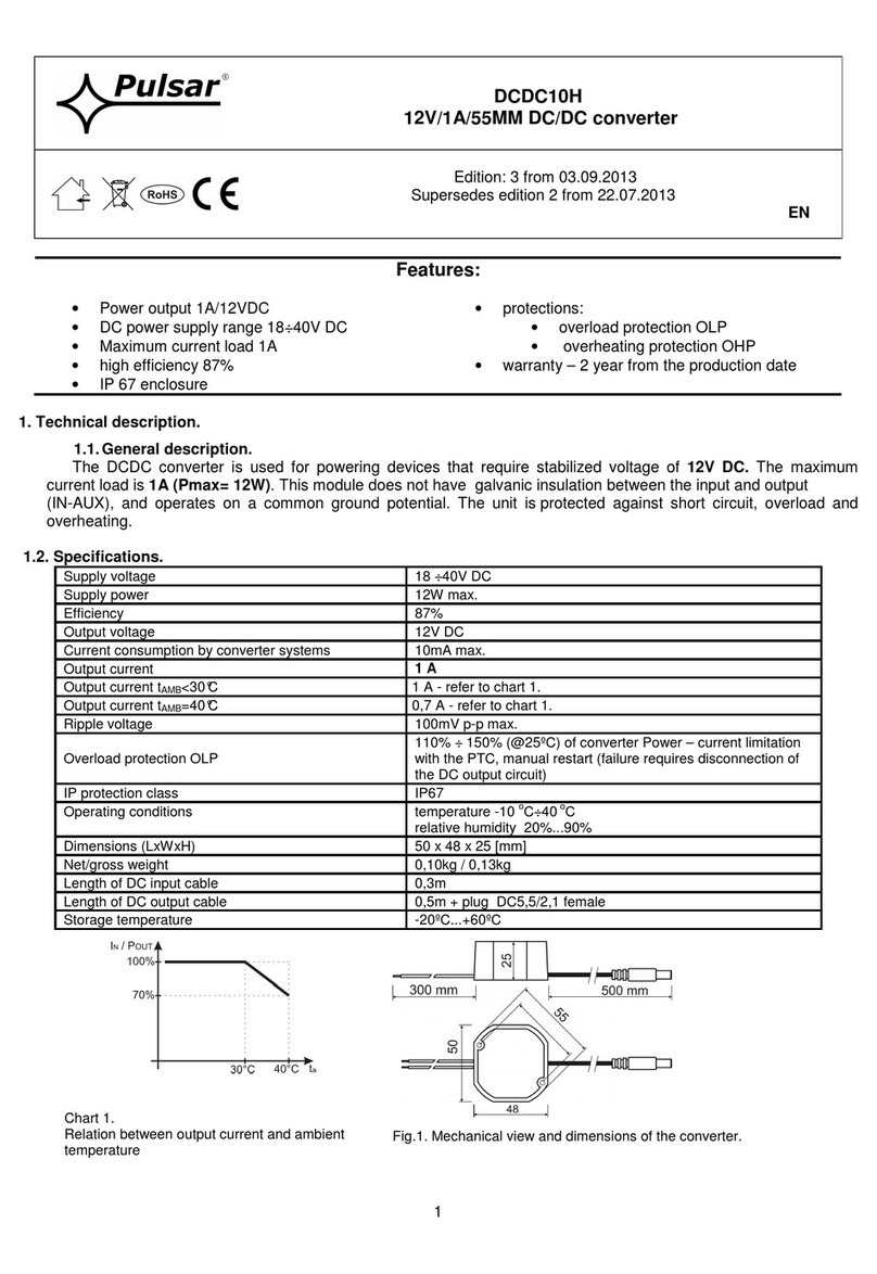
Pulsar DCDC10H User manual

Pulsar

Pulsar DCDC10H User manual

Pulsar DC/DC50SE User manual

Pulsar

Pulsar DC/DC50SE User manual

Pulsar DC/DC48250 User manual

Pulsar

Pulsar DC/DC48250 User manual

Pulsar DC/DC20SD User manual

Pulsar

Pulsar DC/DC20SD User manual

Pulsar DC/DC20SD User manual

Pulsar

Pulsar DC/DC20SD User manual

Pulsar DCDC10 User manual

Pulsar

Pulsar DCDC10 User manual

Pulsar DCDC15H User manual

Pulsar

Pulsar DCDC15H User manual

Popular Media Converter manuals by other brands

TR-Electronic CMS582M-4096/4096 IOL DMS 14H7 KRF Assembly instructions

TR-Electronic

TR-Electronic CMS582M-4096/4096 IOL DMS 14H7 KRF Assembly instructions

Korenix JetCon 2301S user manual

Korenix

Korenix JetCon 2301S user manual

StarTech.com ET91000LCOAM manual

StarTech.com

StarTech.com ET91000LCOAM manual

Alesis AI-3 Reference manual

Alesis

Alesis AI-3 Reference manual

Caton Vpro 5100 user guide

Caton

Caton Vpro 5100 user guide

Cypress CSC-5500 Operation manual

Cypress

Cypress CSC-5500 Operation manual

H&B TX-100 Installation and instruction manual

H&B

H&B TX-100 Installation and instruction manual

Bolin Technology D Series user manual

Bolin Technology

Bolin Technology D Series user manual

IFM Electronic Efector 400 RN30 Series Device manual

IFM Electronic

IFM Electronic Efector 400 RN30 Series Device manual

GRASS VALLEY KUDOSPRO ULC2000 user manual

GRASS VALLEY

GRASS VALLEY KUDOSPRO ULC2000 user manual

Linear Technology DC1523A Demo Manual

Linear Technology

Linear Technology DC1523A Demo Manual

Lika ROTAPULS I28 Series quick start guide

Lika

Lika ROTAPULS I28 Series quick start guide

Weidmuller IE-MC-VL Series Hardware installation guide

Weidmuller

Weidmuller IE-MC-VL Series Hardware installation guide

Optical Systems Design OSD2139 Series Operator's manual

Optical Systems Design

Optical Systems Design OSD2139 Series Operator's manual

Tema Telecomunicazioni AD615/S product manual

Tema Telecomunicazioni

Tema Telecomunicazioni AD615/S product manual

KTI Networks KGC-352 Series installation guide

KTI Networks

KTI Networks KGC-352 Series installation guide

Gira 0588 Series operating instructions

Gira

Gira 0588 Series operating instructions

Lika SFA-5000-FD user guide

Lika

Lika SFA-5000-FD user guide

manuals.online logo
manuals.online logoBrands
  • About & Mission
  • Contact us
  • Privacy Policy
  • Terms and Conditions

Copyright 2025 Manuals.Online. All Rights Reserved.

1
DC/DC50SD
v.1.0
DC/DC 5A Step down DC/DC converter
with adjustable output voltage
EN*
Edition: 2 from 15.01.2016
Supercedes the edition: 1 from 26.08.2015
The module’s features:
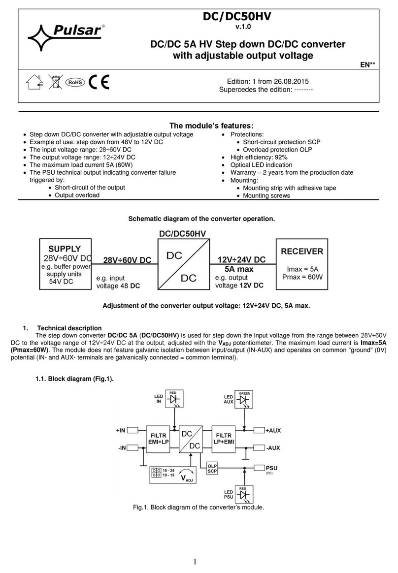
Step down DC/DC converter with adjustable output voltage
Example of use: step down from 24V to 12V DC
The input voltage range: 8÷28V DC
The output voltage range: 4,5÷24V DC
The minimum difference between input (lowered) and output
voltage: 2V
The maximum load current 5A (60W)
The PSU technical output indicating converter failure
triggered by:
Short-circuit of the output
Output overload
Protections:
Short-circuit protection SCP
Overload protection OLP
High efficiency: 92%
Optical LED indication
Warranty –2 years from the production date
Mounting:
Mounting strip with adhesive tape
Mounting screws
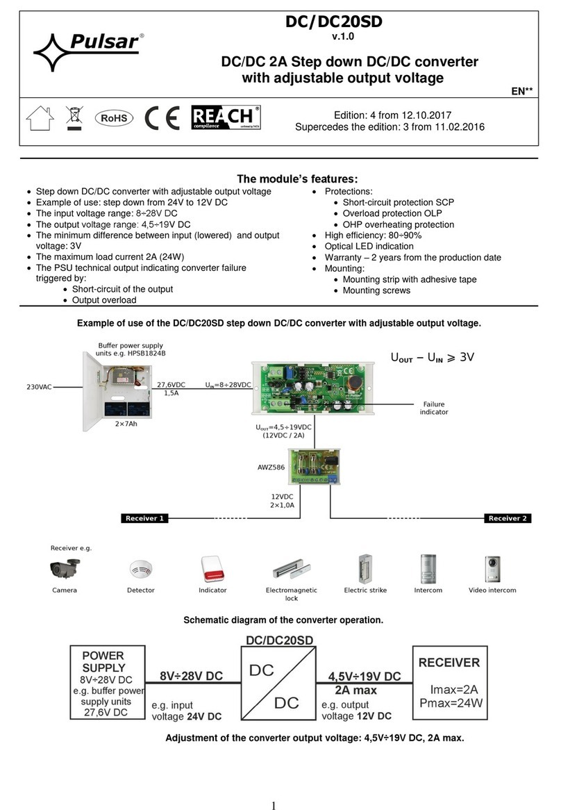
Example of use of the DC/DC50SD step down converter with adjustable output voltage.
Schematic diagram of the converter operation.
Adjustment of the converter output voltage: 4,5V÷24V DC, 5A max.
2
1. Technical description
The step down converter DC/DC 5A (DC/DC50SD) is used for step down the input voltage from the range between 8V÷28V
DC to the voltage range of 4,5V÷24V DC at the output, adjusted with the VADJ potentiometer. The maximum load current is Imax=5A
(Pmax = 60W). The 2V difference between the input (lowered) and output voltage is required for the proper operation of the converter.
The module does not feature galvanic isolation between input/output (IN-AUX) and operates on common "ground" (0V) potential (IN-
and AUX- terminals are galvanically connected = common terminal).
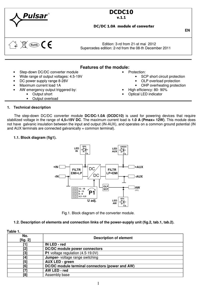
1.1. Block diagram (Fig.1).
Fig.1. Block diagram of the converter’s module.
1.2. Description of components and connectors (Fig. 2, Table 1, Table 2).
Table 1.
No.
[fig.2]
Component’s description
[1]
IN LED light - red
[2]
Power connector of the DC/DC module
[3]
V ADJ voltage adjustment (4,5÷24V)
[4]
Jumper –voltage adjustment
[5]
AUX LED light –green
[6]
The DC/DC module’s connector (power supply and PSU)
[7]
PSU LED light –red
[8]
Mounting strip
Table 2.
[2], [6]
Description of module’s connectors
+IN
- IN
DC supply input
(8V÷28V DC, power consumption from the power source)
+AUX
- AUX
DC supply output
(+AUX= +U, -AUX=GND)
PSU
Technical output of failure (OC type): OLP/SCP activation (short-circuit or overload
protection)
Failure status: hi-Z (high impedance), normal status: L (0V, GND)
Fig.2. The converter module’s view.
3
1.3. Technical parameters:
- Electrical parameters (Table 3)
- Mechanical parameters (Table 4)
Table 3.
The input voltage range (power supply)
8V÷28V DC
depending on the range set by the jumper
The output voltage range
4,5V÷7V, 7V÷10V, 10V÷15V, 15V÷24V
Jumper adjustable.
Factory setting: 12V.
The minimum difference between the input and
output voltage
2V
P module power
60W max. (see fig.3)
Energy efficiency
85%÷ 92%
Ripple voltage
80mV p-p max
Output current
5A max. (see fig.3)
Current consumption by module systems
20 mA max.
Short-circuit protection SCP
electronic, automatic recovery
Overload protection OLP
110-150% of the module’s power, manual restart (the failure
requires disconnection of the DC output circuit)
Technical outputs
- PSU output indicating failure –overload or short-
circuit in the AUX output
- OC type, 50mA max. Failure status: hi-Z state (high
impedance), normal status: L level (0V)
Optical indication
- IN LED indicating DC power status
- AUX LED indicating DC supply status at the output
- PSU LED indicating failure - overload or short-
circuit in the AUX output
- red, normal status: is lit continuously
- green, normal status: is lit continuously
- red, normal status: does not lit, failure: is lit continuously
Operating conditions
II environmental class, -10°C ÷40°C, ensure air flow around
the unit for convection cooling
Declarations, Warranties
CE, 2 years from the production date
Table 4.
Dimensions
L=140, W=43, H=45 [+/- 2mm]
Mounting
tape or mounting screw x 2
Terminals
Ф0,41÷1,63 (AWG 26-14)
Net/gross weight
0,15/0,20 kg
2. Installation.
2.1. Requirements.
The DC/DC converter is to be mounted by a qualified installer, holding relevant permits and licenses (applicable and required
for a given country) for step down installations. The module should be mounted in confined spaces with normal relative humidity
(RH=90% maximum, no condensation) and temperature range from -10°C up to +40°C. The module should operate in vertical position
in order to provide free and convectional air flow.
Proper operation of the module requires adequate current capacity of the power source; the power supply capacity should be
calculated using the formula below: PIN = 1,15 x PAUX
(PIN = 1,15 x IAUX x UAUX)
The module's load balance should be
done prior to installation. During normal
operation, the total current of the receivers should
not exceed I=5A while the power drawn from the
module should not exceed Pmax=60W, as shown
in the Fig. 3.
Fig.3. The maximum output current
depending on the output voltage.
4
Example:
The converter will supply the receivers with a capacity of PAUX = 48W drawing a total current of IAUX = 4A at the voltage
UAUX = 12V. The minimum power supply capacity must therefore amount to: PIN = 1,15 x 4A x 12V = 55,2W.
The device should be mounted in a metal enclosure (cabinet). The rules for power supply, enclosures and shielding - according to
application - must be observed in order to meet the requirements of LVD and EMC directives.
2.2. Installation procedure.
1. Mount the enclosure (cabinet, etc.) and lead cables through cable glands.
2. Mount the DC/DC converter with adhesive tape or mounting screws.
3. Supply DC voltage to the + IN, -IN terminals with correct polarization. The supply voltage should be selected according to the table
and depending on the output voltage:
4. Switch on the DC voltage.
5. Use the jumper to set the required voltage range and adjust the required output voltage with the VADJ potentiometer. Default setting:
12V.
6. Switch off the DC voltage.
7. Connect the receivers’ cables to the +AUX, -AUX connectors of the terminal block on the module’s board.
8. Connect the device cables (alarm control panel, indicator, LED light, etc.) to the PSU technical output if necessary.
9. Switch on the DC voltage (the red IN LED should be permanently illuminated, the AUX green LED should be permanently
illuminated).
10. Once the tests and operation control are performed, close the enclosure, cabinet, etc.
3. Converter 's module operation indication.
3.1. Technical output.
The converter is equipped with three diodes indicating operation status: IN, AUX, and PSU.
IN- red LED: during normal status (DC power supply) it is lit continuously. No DC supply is indicated by switching off the IN LED.
AUX- green LED: indicates DC supply status at the module’s output. During normal status, it is lit continuously, in case of short
circuit or overload the AUX led is off.
PSU- red LED: indicates module’s overload. During normal status, it is off, in case of short circuit or overload the LED lights
continuously.
3.2. Technical output.
The converter is fitted with one technical output indicating failure of the DC / DC module.
PSU- OLP/SCP (overload/short-circuit) output: - OC type output indicating overload/short-circuit of the module’s output.
During normal operation, the output is shorted to the AUX - (0V). In case of failure, the module disconnects the output and it is in the hi-
Z (high impedance) state during failure.
4. Maintenance and operation.
4.1. Converter overload.
The AUX output is protected with the PTC polymer fuse. If the load current exceeds Imax (110% ÷ 150% @ 25ºC of the
converter capacity), the output voltage will be automatically disconnected, which will be signaled by switching off the green AUX LED,
switching on the red PSU LED and a change in the status of the technical output. Voltage restoration requires disconnecting the output
load for approx. 1 min.
5. Maintenance.
All maintenance procedures can be performed after disconnecting the converter from the power network. The converter does
not require any specific maintenance; however, its interior should be cleaned with compressed air if used in dusty conditions.
WEEE LABEL
Waste electrical and electronic equipment must not be disposed of with normal household waste.
According to the European Union WEEE Directive, waste electrical and electronic equipment should
be disposed of separately from normal household waste.
DC input voltage
DC output voltage
8÷28V
4,5÷6V
12÷28V
4,5÷10V
17÷28V
4,5÷15V
26÷28V
4,5÷24V
Pulsar
Siedlec 150, 32-744 Łapczyca, Poland
Tel. (+48) 14-610-19-40, Fax. (+48) 14-610-19-50
e-mail: biuro@pulsar.pl, sales@pulsar.pl
http:// www.pulsar.pl, www.zasilacze.pl