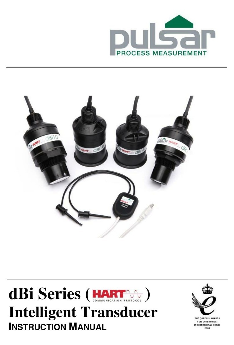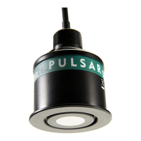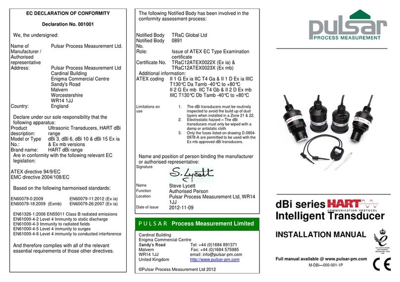
The installation is now complete; refer to the PULSARultra user
manual for instructions on how set up the PULSARultra instrument.
EN1092 (BS 4504) All dimensions in mm
ANSI Class 150 All dimensions in mm
Wire the transducer into the relevant PULSARultra instrument as
shown in figure 6. Terminal numbers will depend on the unit.
The dBi Profibus PA transducer range has been specified and
designed to meet the demanding requirements of today’s process
level measurement applications for liquids and solids.
All dBi Profibus PA transducers are 2 wire and draw approx. 20mA
from the bus. The dBi Profibus PA transducers are set up using either
a Profibus PA network or Pulsar PA modem and PA PC software
package.
The dBi Profibus PA transducer is based on a PZT ceramic element.
The nominal beam angle is 10 0 @ -3 dB (depending on unit). When
coupled with the DATEM®signal processing they provide unmatched
performance in industrial process level measurement.
All dBi Profibus PA transducers are fitted with internal temperature
compensation.
Optional submersion shield is available to prevent spurious signal if
the transducer becomes submerged.
A range of flange mounting options (ANSI & EN1092) with or
without a PTFE facing to give improved chemical resistance is
available.
An aiming kit is recommended for solids level measurement, to help
focus on the material surface angle of repose.
Standard cable lengths: 5, 10, 20 or 30m.
Process Connection: 1” BSP & M20 adaptor
Operating Temperature: -40 to +80°C
Ingress Protection: IP68
Enclosure Material: Valox 357
The dBi Profibus PA transducer should be installed directly above
the liquid or solid level with the transducer axis perpendicular to the
surface to be measured.
The transducer can be installed using the 1” BSP thread on the top
of the transducer or with the supplied 1” BSP to M20 thread adapter.
See figure 1 for example.
In some applications, it may not be possible to install the transducer
using either a flange or the 1” BSP thread, in these circumstances it
may be possible to suspend the transducer from its cable. In these
installations, it is recommended that the transducer be secured using
a small chain fitted to one of the chain holes on the top of the
transducer, see figure 2.
When installing the transducer avoid aiming the transducer directly
at fixed obstructions as they may mask the required return echo from
the liquid or solid level being monitored, see figure 3.
Flanged versions of the transducer should be installed using plastic bolts with an insulating
gasket between the transducer flange and the process vessel flange. The bolts should not
be fully tightened as this may cause acoustic resonance that results in increased ring down.
A typical flange application is shown above.
HAZARDOUS AREA INSTALLATION
dBi Profibus PA transducers are ATEX certified for use in hazardous
areas. The product is certified as Ex ia and for FISCO (see label for
more information), they are certified for use in Zone 0,1 & 2 when
used with the correct barriers.
The ‘X’ in the Certification No.’s indicates that certain special
conditions apply. See EU Declaration of Conformity on the flip side
of this document.
Wiring Detail
ATEX labelling for the two versions of protection Ex ia & FISCO
X Limitations on use:
1. Electrostatic hazard –The dBi transducers must only be wiped with a
damp or anti-static cloth.
2. Special condition of safe use: The Profibus PA transducer must be
powered by either an ATEX approved barrier or FISCO ATEX approved
power supply that meet the following parameters:
3. The dBi transducers must be routinely inspected to avoid the build-up
of dust layers when installed in Zones 20, 21 & 22.
4. The power supply cable to the transducers shall meet the relevant
installation requirements of clause 9, EN60079-14.
5. The equipment is considered suitable for use in a FISCO system only
when it is installed in accordance with EN60079-25.
The dBi Profibus PA transducer is designed to work in a Profibus
system. The Profibus PA devices are normally connected to a
Profibus DP system via a segment coupler.
A segment coupler translates the DP messages to PA and vice
versa, it also performs a transfer rate change as Profibus PA bus
normally runs at 31.25KBaud, whereas the DP bus can run up to 12
MBaud. The PA devices on the segment coupler are addressed
transparently by the Profibus DP Master.
The number of devices that can be placed on the PA bus is
dependent on the segment coupler used and the power requirements
of the PA devices. The Pulsar dBi Profibus PA transducer draws
20mA in normal operation.
The segment coupler will be designed either Exia or FISCO. The
FISCO standard allows for more current in the PA bus meaning more
PA field devices can be powered from one bus.
The cable length on a PA bus should not exceed 1000m.


