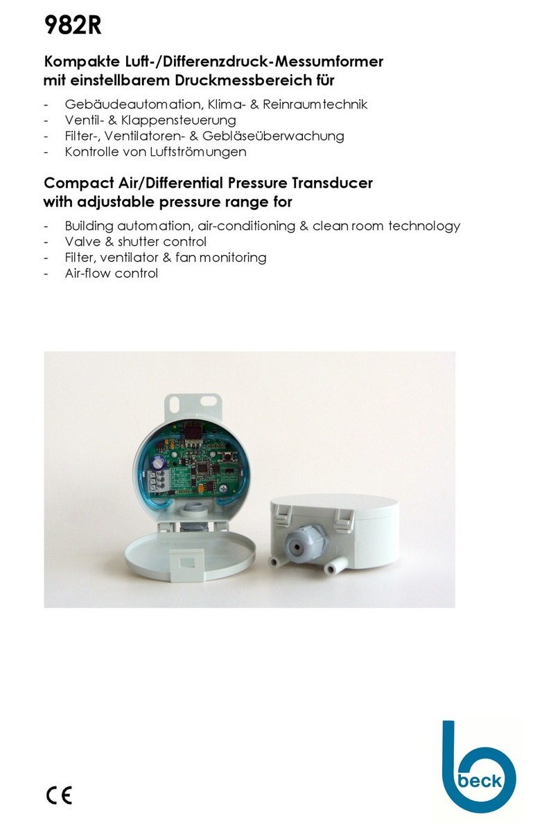
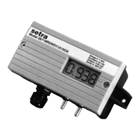
Beck 982R Series User manual

982R
Kompakte Luft
-
/Differenzdruck
Messumformer mit einstellbarem
Druckmessbereich für
- Gebäudeautomation, Klima- & Reinraumtechnik
- Ventil- & Klappensteuerung
- Filter-, Ventilatoren- & Gebläseüberwachung
- Kontrolle von Luftströmungen
Compact Air/Differential
Pressure Transducer with adjustable
pressure
range for
- Building automation, air-conditioning & clean room technology
- Valve & shutter control
- Filter, ventilator & fan monitoring
- Air-flow control
SICHERHEIT & PRODUKTHAFTUNG
SAFETY & LIABILITY
Dieses Produkt darf nur von ausgebildeten Fachleuten montiert, angeschlossen und in Betrieb genommen
werden. Die geltenden Sicherheitsbestimmungen, Verwendungszweck und technischen Daten sind einzuhalten.
Gemäß diesen Bestimmungen müssen Anlagen spannungsfrei geschaltet und vor unbeabsichtigtem Wiederein-
schalten gesichert werden. Beschädigte Produkte dürfen nicht verwendet werden. Das Produkt darf nicht für U.S.
FDA kontrollierte Anwendungsbereiche verwendet werden. Für Schaden, die durch unsachgemäße Verwendung
entstehen, z.B. bei Öffnung des Gerätes oder Beschädigung des Siegels, wird keine Haftung übernommen.
The product mentioned in this manual may only be installed, connected and put into operation by trained
pr
ofessionals. The existing safety regulations, the intended use and the technical data must be strictly observed.
According to these regulations, applications must be at zero
-potential and secured against inadvertently restart.
Damaged products may not be used. The product may not be used for U.S. FDA controlled application areas. For
damage caused by improper use no liability is assumed. Opening the device or breaking the seal will void the
warranty.
ELEKTRISCHER ANSCHLUSS
ELECTRICAL CONNECTION
GEFAHR DURCH STROMSCHLAG: Bei Arbeiten an der Elektrik darf keine Spannung anliegen. Durchführung
der Arbeiten entsprechend den gesetzlichen Vorschriften vornehmen. Kabelisolierung muss für Dichtigkeit in
Gehäuse eingeführt werden. Passende Klingenbreite für Klemmschrauben verwenden.
DANGER OF ELECTRIC SHOCK: No voltage must be applied if you work on electric systems. Carry out the
service work according to legal rules. Cable insulation must be done into the housing in a way that tightness is
preserved.
Use a matching screwdriver for the clamping screws.
ENTSORGUNG
DISPOSAL
Die meisten unserer Produkte enthalten wertvolle Rohstoffe und sollten deshalb einem geordneten Recycling zugeführt werden.
Bitte beachten Sie die geltenden nationalen Vorschriften, Gesetze und Regelungen.
Most of our products may contain valuable materials that should be recycled and not disposed of as domestic waste. Please
observe the applicable relevant regulations and laws.

BESTELLMATRIX
982R. 6
X
X
X
0
X
ORDER MATRIX
I
II
III
IV
V
VI
Bestell
-
Code
I
Schutzart IP54 /
Protection category IP54 Order code
mit Hutmutterverschraubung SW15 / with cap nut conduit AF15 6
II
Auswählbare Druckmessbereiche /
Selectable pressure ranges
0…100 Pa
/
100 Pa ( 0…1,0 mbar / 1.0 mbar )2
0…250 Pa
/
250 Pa ( 0…2,5 mbar / 2.5 mbar )3
0…500 Pa
/
500 Pa ( 0…5,0 mbar / 5.0 mbar )4
0…1 kPa /
1 kPa ( 0…10 mbar / 10 mbar )5
0…2,5 kPa /
2.5 kPa ( 0…25 mbar / 25 mbar )6
0…5 kPa /
5 kPa ( 0…50 mbar / 50 mbar )7
0…10 kPa /
10 kPa ( 0…100 mbar / 100 mbar )8
0…25 kPa /
25 kPa ( 0…250 mbar / 250 mbar )9
0…50 kPa /
50 kPa ( 0…500 mbar / 500 mbar )A
0…100 kPa /
100 kPa ( 0…1,0 bar / 1.0 bar )B
III
Druckeinheit
/
Pressure unit
mbar 1
Pascal 3
IV
Ausgangssignal
/
Output signal
0 …10 V, 3-Leiter, linear / 0 …10 V, 3-wire, linear 7
4 …20 mA, 3-Leiter, linear / 4 …20 mA, 3-wire, linear D
0 …10 V, 3-Leiter, radiziert / 0 …10 V, 3-wire, square root L
4 …20 mA, 3-Leiter, radiziert / 4 …20 mA, 3-wire, square root P
4 …20 mA, 2-Leiter, linear / 4 …20 mA, 2-wire, linear 2
4 …20 mA, 2-Leiter, radiziert / 4 …20 mA, 2-wire, square root U
V
Anzeige
/
Display
Ohne Anzeige / without display 0
VI
Elektrischer Anschluss /
Electrical connection
Über Federklemme / Using spring terminals 6
Rundsteckverbinder M12 / 4-polig / Using circular connectors M12 / 4-pole 8
DRUCKMESSBEREICHE
PRESSURE RANGES
Baureihe
Model
Druckbereich
Pressure range
Überdruck
Sicherheit
Over pressure
safety
Berstdruck
Burst pressure
Zusätzliche Unsicherheit
durch Temperatur [% FS/10K]
Additional uncertainty with
temperature [% FS/10K]
982R.623 0 …100 Pa / 100 Pa 60 kPa 100 kPa ± 1,0
/ ± 1.0
982R.633 0 …250 Pa / 250 Pa 60 kPa 100 kPa ± 0,7
/± 0.7
982R.643 0 …500 Pa / 500 Pa 75 kPa 125 kPa ± 0,5
/± 0.5
982R.653 0 …1 kPa / 1 kPa 75 kPa 125 kPa ± 0,3
/± 0.3
982R.663 0 …2,5 kPa / 2.5 kPa 85 kPa 135 kPa ± 0,3
/± 0.3
982R.673 0 …5 kPa / 5 kPa 85 kPa 135 kPa ± 0,3
/± 0.3
982R.683 0 …10 kPa / 10 kPa 85 kPa 135 kPa ± 0,3
/
± 0.3
982R.693 0 …25 kPa / 25 kPa 135 kPa 275 kPa ± 0,3
/
± 0.3
982R.6A3
0 …50 kPa / 50 kPa 200 kPa 400 kPa ± 0,3
/
± 0.3
982R.6B3
0 …100 kPa / 100 kPa 200 kPa 400 kPa ± 0,3
/
± 0.3
Weitere Druckmessbereiche auf Anfrage / Further pressure ranges upon request
ANALOGAUSGANG
ANALOG OUTPUT SIGNAL
Linear Radiziert / Square root
0 –10 V 4 –20 mA 0 –10 V 4 –20 mA

TECHNISCHE DATEN
TECHNICAL DATA
2-
Leiter Ausführung
2-wire version 3-
Leiter Ausführung
3-wire version
Versorgungsspannung Supply Voltage 18...30 VDC 18...30 VAC / DC
Ausgangssignal Output signal 4...20 mA 0...10 V oder / or 4...20 mA
Bürde für Ausgang
4…20 mA Working resistance for output
4…20 mA 20...500 Ω
Bürde für Ausgang
0…10 V Working resistance for output
0…10 V - ≥1kΩ(≤10 mA)
Max. Stromaufnahme Max. current draw < 21 mA < 40 mA oder / or < 60 mA
Druckmedium Pressure medium Luft und nicht aggressive Gase / Air and non aggressive gases
Messverfahren Measuring process Piezoresistiver Drucksensor / Piezoresistive pressure transducer
Linearität
(inkl. Hysterese und
Reproduzierbarkeit)
Linearity
(incl. hysteresis and
repeatability) ≤±0,5% FS, min. ±1 Pa / ≤±0.5% FS, min. ±1 Pa
Unsicherheit
(Gesamtfehler ohne Langzeit-
und Temperatureinfluss)
Uncertainty
(Total Error Band w/o long-
term and temperature effects) ±1% FS, min. ±1 Pa
Langzeitstabilität Long-term stability ≤±1% FS, min. ±1 Pa
Betriebs- und
Lagertemperatur Operating and storage
temperature -10...70 °C (14…158 °F)
Feuchte Humidity 0...95 % rel., nicht kondensierend / 0...95 % rel., non condensing
Ansprechzeit umschaltbar Response time selectable 1 s (Standard) oder 200 ms / 1 s (default) or 200 ms
Prozessanschluss Pressure connection 6 mm Schlauchstutzen / 6 mm hose connection
Elektrischer Anschluss Electrical connection
Federklemmen für Drähte und Litzen bis 1,5 mm
2
oder
Rundsteckverbinder M12 / 4-polig
Spring connector for cable and leads up to 1.5 mm2or
circular connectors M12 / 4-pole
Befestigung Mounting Schraubbefestigung mit Kerbschrauben
Screw fastening with sheet metal screws
Gehäusematerial Casing material ABS
Gehäuseabmessungen Casing dimensions Ø 66 x 28 mm
Gewicht Weight ca. 50 gr / appr. 50 g
Schutzart nach EN60529 Protection to EN 60529 IP 54
Kabeldurchführung Cable conduit Hutmutterverschraubung SW15 aus Polyamid
Cap nut conduit AF15 made of polyamide
Normen / Konformität Standards / Conformity EN 61326 (CE), 2011/65/EWG (RoHS II)
Genauigkeitsangaben nach EN 60770 bezogen auf die Druckmessung bei 23°C
Accuracy specifications according to EN 60770 based on the pressure measurement at 23 °C
FUNKTION DES TASTERS
FUNCTION OF BUTTON
Funktion
Function
Zeit
Time
Hinweis (nur
bei
3
-
Leiter)
Reference (only at 3-wire)
Beschreibung der Funktion
Decription of Function
1 0 …5 s LED leuchtet
LED lights Nullpunktverschiebung
Set zero point
2 5 …10 s LED blinkt
LED flashes Messbereichsanpassung
Adjust the measuring range
3 > 10 s LED geht aus
LED goes OFF Reset (Werkseinstellungen)
Reset (factory settings)
1.
Nullpunktverschiebung /
Set zero point
Der Nullpunkt kann durch Drücken des Tasters (0…5 Sek.) beliebig verschoben werden. Wird die Nullpunktverschiebung im
drucklosen Zustand durchgeführt, ist es vergleichbar mit einem Offsetabgleich. Führt man die Nullpunktverschiebung bei
angelegtem Druck „x“durch, wird der gesamte Messbereich um den Druck „x“verschoben. Die LED leuchtet bei 3-Leiter
Ausführung zu
r Bestätigung der Einstellung. Bei Erstinbetriebnahme oder Lageänderung ist ein Offsetabgleich zu empfehlen.
The zero point can be adjusted by pressing the button (0…5 sec). If this is performed without an applied pressure this compares to
a zero pressure offset calibration. If performed with an applied pressure ”x”, the entire pressure range will be shifted by this
pressure “x”. The LED lights to confirm the adjustment at 3
-wire version. Offset calibration is recommended for initial start-up or
change in position.
2.
Einstellung des
Messbereichsende
/
Set measuring range end
Das Messbereichsende kann zwischen 50%...100% vom Druckmessbereich eingestellt werden. Der gewünschte Druck wird an
P+ angelegt und der Taster wird für 5…10 Sek. gedrückt. Bei 3-Leiter Ausführung blinkt die LED zur Bestätigung der Einstellung.
Das Ausgangssignal 0 …10 V / 4 …20 mA entspricht dann dem neu eingestellten Messbereich.
The end of the measuring range can be set between 50%...100% of its factory set full scale value. Make sure pressure port P- is
open, then apply the designated end of pressure range to port P+. To confirm press button for 5…10 sec. LED flashes to confirm
the setting at 3-wire version. The output signal 0 ... 10 V / 4 ... 20 mA corresponds to the new measuring range.

3.
Zurück zu Werkseinstellungen /
Back to factory settings (Reset)
Diese Funktion bietet die Möglichkeit das Gerät auf die Werkseinstellungen zurück zu setzen. Um alle vorgenommenen
Einstellungen (Nullpunkt und Messbereichsende) am Gerät zurückzusetzen, wird der Taster länger als 10 Sek. gedrückt. Die LED
erlischt bei 3-Leiter Ausführung zur Bestätigung der durchgeführten Rückstellung.
This feature provides the possibility to reset the transmitter to the original factory settings. If the button is pressed for longer than
10 seconds, all settings (Zero point and measuring range end) are reset to the device. The LED goes off to confirm the correct
reset at 3-wire version.
MONTAGE / ABMESSUNG
INSTALLATION / DIMENSIONS
Der Differenzdruck-Messumformer
kann in beliebiger Einbaulage montiert
werden. Durch den Null
punktabgleich
wird der Lagefehler eliminiert.
The differential pressure transducer
can be mounted in any position. The
zero compensation eliminates errors
due to positioning.
Elektrische Anlagen dürfen nur durch autorisierte Elektrofachkräfte
errichtet, erweitert, geändert und in Stand gehalten werden.
Electrical equipment may only be installed, added to, changed or
maintained by authorized electricians.
BEFESTIGUNG & SCHLAUCHANSCHLUSS
MOUNTING & HOSE CONNECTION
WICHTIG: Schläuche dürfen beim Anschließen und Verlegen nicht geknickt oder beschädigt werden. Undichte Schläuche und
Schlauchanschlüsse verursachen Störungen am Gerät oder liefern falsche Messergebnisse.
Ø innen = < 3,5 / 5,5 mm für optimale Klemmung. Ab 25 kPa Schlauchklemme verwenden.
P1 = Überdruckmessung
P2 = Unterdruckmessung
P1 & P2 = Differenzdruckmessung
IMPORTANT: Pressure hoses may not be bent or damaged during installation. Leaking hoses and hose connections will cause
errors on the device or inaccurate measurements.
Inner Ø = < 3.5 / 5.5 mm for optimal clamping. From 25 kPa hose clamps must be used.
P1 = positive pressure measurement
P2 = negative pressure measurement
P1 & P2 = Differential pressure measurement
Klemmenbelegung
Terminal assignments
3-Leiter / 3-wire
2-Leiter / 2-wire
8.930.108-2
Federklemme
2-oder 3-polig /
Spring terminals
2- or 3-pole
123
Rundsteck
-
verbinder M12
4-polig / Circular
connectors
M12 4-pole
3 Masse (GND)
Ground (GND)
2 Ausgangssignal (0…10 V / 4…20 mA)
Output signal (0…10 V / 4…20 mA)
1 Versorgungsspannung (18...30 VAC / VDC)
Supply voltage (18...30 VAC / VDC)
2 Ausgangssignal (4…20 mA)
Output signal (4…20 mA)
1 Versorgungsspannung (18...30 VDC)
Supply voltage (18...30 VDC)
2 Nicht belegt / Not used
3 Masse (GND) / Ground (GND)
4 Ausgangssignal (0…10 V / 4…20 mA)
Output signal (0…10 V / 4…20 mA)
1 Versorgungsspannung (18...30 VAC / VDC)
Supply voltage (18...30 VAC / VDC)
2 Ausgangssignal (4…20 mA)
Output signal (4…20 mA)
3 Nicht belegt / Not used
4 Nicht belegt / Not used
1 Versorgungsspannung (18...30 VDC)
Supply voltage (18...30 VDC)
982R_manual_german_english
8.930.108
-
2
Te
chnische Änderungen vorbehalten
/
Technical data subject to change without prior notice
.
Copyright ©
2019
Beck GmbH
This manual suits for next models
10
Other Beck Transducer manuals
Popular Transducer manuals by other brands
Balluff
Balluff BTL6-U110-M****-PF-S4 series user guide
NK TECHNOLOGIES
NK TECHNOLOGIES DTC 2-420-24U-FL instructions

Johnson Outdoors
Johnson Outdoors Cannon Digi-Troll IV manual
Balluff
Balluff BTL7-A5-M Series user guide
Setra Systems
Setra Systems 526 installation guide

PCB Piezotronics
PCB Piezotronics 2302-110-02A Installation and operating manual
