manuals.online logo
Brands
  1. Home
  2. •
  3. Brands
  4. •
  5. NK TECHNOLOGIES
  6. •
  7. Transducer
  8. •
  9. NK TECHNOLOGIES AT-TH Series User manual

NK TECHNOLOGIES AT-TH Series User manual

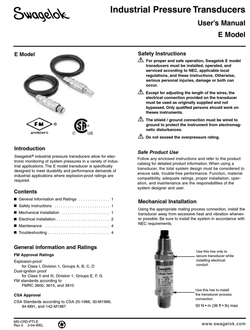
INSTRUCTIONS
1. Mount AT/ATR-TH Current Transducer to DIN rail or
panel in suitable enclosure.
2. With monitored load off, install each phase through the
sensing windows. Designate one phase as A, B and C.
3. Select the current range using the slide switch.
4. Connect output terminals + and - using 22-14 AWG
copper wires rated 70/90°C. Tighten to 5-7 inch-pounds
torque.
5. Connect power supply voltage to terminals 9-10
6. The output will be proportional to the current in each
phase, plus one which is the average of the three.
7. Any of four analog signals can be used independently, or
all four can be used at the same time.
AT/ATR-TH Series
AC Current Transducer
w/Proportional Analog Outputs
Model Number KeySpecifications
Quick “How To” Guide
APT-TH Instruction Sheet Rev 2 04/18 p/n 292000609
OtherAvailable Products Include:
DC Current Switches, Ground Fault Sensors
AC & DC Current Switches
Power Transducers
Current & Potential Transformers (CTs&PTs)
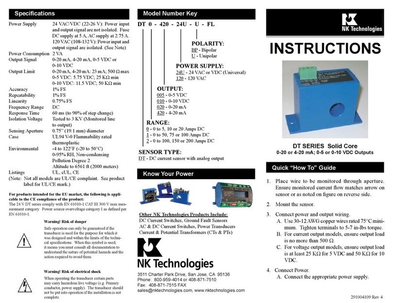
Power Supply 24 VAC/DC( +/- 10%) Note: Not isolated
from output signal.
NOTE: Power Supply and output signal ARE NOT isolated. Do
not connect the negative terminals to a common point when
using the 24 V powered models.
120 VAC (+/-10%) Note: Power supply
is isolated from output signal.
Power Consumption <6.0 VA
Outputs Four outputs, three proportional to the
current in that phase, one an average of
all three.
Signal Type Impedance
4-20 mA <500 Ω
0-5 VDC >2K Ω
0-10 VDC >2K Ω
Accuracy 1% FS
Response Time 220 ms (to 90% of step change)
Frequency Range AT: 50-60 Hz
ATR: 30-100 Hz
Over Current Limit 6X range setting for one second
Output Terminals Finger-safe captive screw, 14-22 AWG
Torque to 5-7 inch-pounds
Isolation Voltage To 1250VAC
Enclosure ABS, UL94 V0 Flammability rated
Environmental -4 to 122°F, -20 to 50°C
Approvals UL/cUL listed E342812
3511 Charter Park Drive, San Jose, CA 95136
Toll free: 800-959-4014, Phone: 408-871-7510
Fax: 408-871-7515
[email protected], www.nktechnologies.com
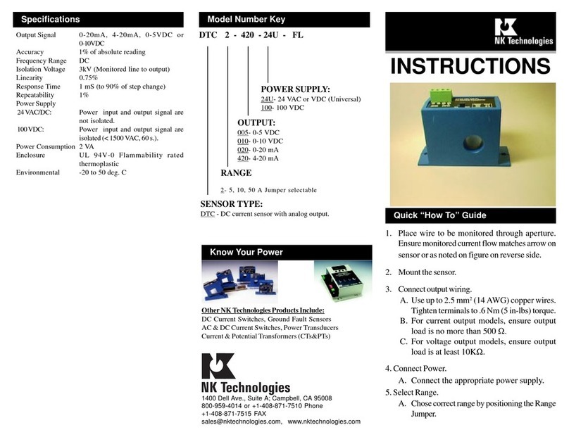
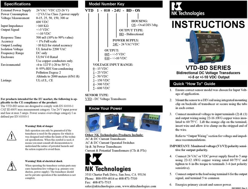
ATR 3 - 420 - 24U - TH
Output Signal
420 4-20mA
005 0-5 VDC
010 0-10 VDC
Power Supply
24U 24 VAC/DC (non-isolated)
120 120VAC (isolated)
Current Ranges
1 0-10, 0-15 and 0-30A
2 0-30, 0-50, and 0-100A
3 0-100, 0-150 and 0-200A
AT: Average Responding
ATR: True RMS
Housing Type
TH Three Hole
Output Signal
Impedance Limits
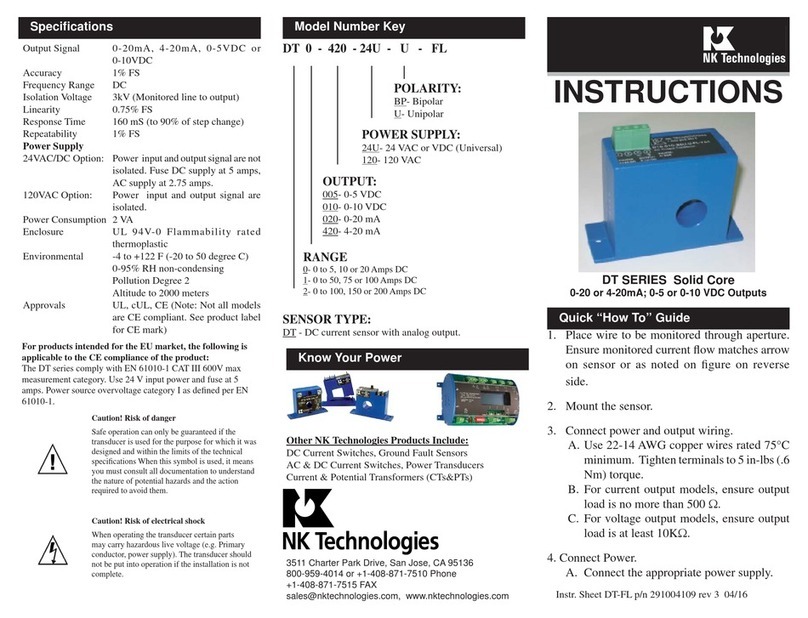
AT/ATR-TH Series current transducers are intended to
monitor consumption of three phase loads. They provide
an analog signal proportional to the current in each of the
three phases, and another which will be proportional to the
average of the three phase currents. The transducer can be
mounted on a back panel using screws through the mounting
holes in the base or snapped onto a DIN rail. Each model
can be set for three current measurement ranges.
Description
Wiring
Wiring Schematic Diagram
Output Signal:
Connect positive signal to controller or display using 75/90°
C rated copper wire, tighten the terminals on the transducer
to 5-7 inch-pounds torque. Confirm that the connected load
impedance is less than 500 Ωfor current signals or at least
2K Ωfor voltage signals.
Monitored Circuit:
Each of the three phases pass through the three windows
of the top section. All conductors should pass through the
sensor in the same direction (from the front or the back)
for appearance, but not required for accuracy or reliability.
If the phases use multiple conductors, all wires of one phase
must pass through the same sensing window or aperture.
The transducer is designed to monitor circuits to 600 VAC,
whether the conductor is insulated or bare. Each aperture has
an inside diameter of 0.74” (18.8 mm), allowing 4/0 THHN
(120 mm²) to pass through easily. Centering the conductor
in the aperture is not necessary.
NC NO
12 345678
0-10 VDC
0-5 VDC
4-20 mA
LOW MID HIGH
RANGE
SELECTION
SWITCH
POWER
NO POLARITY
++ ++
+-
PLC,
Controller, etc.
9
10
MONITORED CIRCUIT CONDUCTORS
--
--
ABCAverage
Top View
1. Sensor has no output:
A. Power source is not energized or connected to the
transducer. Check voltage at terminals 9 and 10. 24V
models do not have isolation between the power and the
output signals.
B. The monitored circuit is not energized or drawing cur-
rent. Check that the monitored circuit is energized.
C. Polarity is not properly matched. The output signals
are polarity sensitive, and the result would be no signal
through the HMI or whatever is reading the transducer
outputs.
2. Output Signal Too Low
A. The transducer range may be too high to read the
monitored circuit current. Select a model with a lower
range, or loop each conductor through the sensing win-
dows to increase the current through each aperture.
B. Power supply may not enough capacity to operate the
transducer outputs. use a power supply with at least 6VA
available to operate the transducer.
3. Outputs are always at the minimum (4mAor zero
volts)
A. The Monitored load is not energized or is not AC. Be
sure that the monitored circuit is AC with a frequency
between the model limits (AT average responding 50 to
60 hertz, RMS models 30 to 100 hertz).
4. Outputs are always at the maximum (20mAor 5 or
10 volts)
A. The Monitored load is drawing more current than the
transducer range. Select a model with a higher range, or
set the range selection to a higher range. Be very careful
when selecting the model to suit the application. Check
the range selection slide switch. Check the actual cur-
rent used with a hand held ammeter, and set the range
accordingly.
Power Supply:
Connect power supply to transducer as shown in wiring
diagram. Use 75/90° C rated copper wire. The power sup-
ply terminals are not polarity sensitive. Tighten terminals
to 5-7 inch-pounds torque. For 24 volt powered models,
use a Class 2 power limited source and fuse at 5 amps
maximum.
For 120 volt powered models, fuse at 5 amps maximum.
Troubleshooting
ABC
Application:
Monitoring current is a great tool to use in a preventative
maintenance program. All loads are protected against
high level of over current with a circuit breaker or fuses,
but monitoring over time can detect small increases in
current which point to failing bearings or the need for
lubrication. Detecting under current conditions is just as
important, but much more complicated than over current
detection. If a pump has a blocked or restricted intact or
discharge, the drive motor will draw less than normal
current. The pump is not pushing the product as it was de-
signed, but moving only the product in the impeller cavity.
A pump with an open intake or discharge will also draw
less than normal current. Either condition can cause a
lot of damage, but when the discharge is open, some very
hazardous material can be spread quickly.
Under current is also seen when a belt breaks, comes
off the sheave grooves or needs to be tightened; or if a
coupling shears or is loose.
This manual suits for next models

2

Other NK TECHNOLOGIES Transducer manuals

NK TECHNOLOGIES AT 2 Series User manual

NK TECHNOLOGIES

NK TECHNOLOGIES AT 2 Series User manual

NK TECHNOLOGIES DT Series User manual

NK TECHNOLOGIES

NK TECHNOLOGIES DT Series User manual

NK TECHNOLOGIES APS Series User manual

NK TECHNOLOGIES

NK TECHNOLOGIES APS Series User manual

NK TECHNOLOGIES ATQ Series User manual

NK TECHNOLOGIES

NK TECHNOLOGIES ATQ Series User manual

NK TECHNOLOGIES VTD Series User manual

NK TECHNOLOGIES

NK TECHNOLOGIES VTD Series User manual

NK TECHNOLOGIES AT SERIES User manual

NK TECHNOLOGIES

NK TECHNOLOGIES AT SERIES User manual

NK TECHNOLOGIES DT Series User manual

NK TECHNOLOGIES

NK TECHNOLOGIES DT Series User manual

NK TECHNOLOGIES DTC 2-420-24U-FL User manual

NK TECHNOLOGIES

NK TECHNOLOGIES DTC 2-420-24U-FL User manual

NK TECHNOLOGIES APS Series User manual

NK TECHNOLOGIES

NK TECHNOLOGIES APS Series User manual

NK TECHNOLOGIES VTD-BD Series User manual

NK TECHNOLOGIES

NK TECHNOLOGIES VTD-BD Series User manual

NK TECHNOLOGIES VTR Series User manual

NK TECHNOLOGIES

NK TECHNOLOGIES VTR Series User manual

NK TECHNOLOGIES VTU Series User manual

NK TECHNOLOGIES

NK TECHNOLOGIES VTU Series User manual

NK TECHNOLOGIES VTU Series User manual

NK TECHNOLOGIES

NK TECHNOLOGIES VTU Series User manual

Popular Transducer manuals by other brands

Endress+Hauser Cerabar PMP23 operating instructions

Endress+Hauser

Endress+Hauser Cerabar PMP23 operating instructions

Balluff Micropulse BTL5-A series user guide

Balluff

Balluff Micropulse BTL5-A series user guide

Minebea TWOFB-NM Series Operation manual

Minebea

Minebea TWOFB-NM Series Operation manual

MESSKO Pt-MU operating instructions

MESSKO

MESSKO Pt-MU operating instructions

Simrad LOWRANCE TotalScan installation manual

Simrad

Simrad LOWRANCE TotalScan installation manual

WIKA WUD-20 operating instructions

WIKA

WIKA WUD-20 operating instructions

PICO WPS600C user guide

PICO

PICO WPS600C user guide

Camille Bauer SIRAX BT5100 manual

Camille Bauer

Camille Bauer SIRAX BT5100 manual

Siedle novotechnik RFC-4800 user manual

Siedle

Siedle novotechnik RFC-4800 user manual

Simrad 38-200 COMBI C -  REV D installation manual

Simrad

Simrad 38-200 COMBI C - REV D installation manual

Desoutter DRT5 Sq 5000 User instructions

Desoutter

Desoutter DRT5 Sq 5000 User instructions

BDI ST350 Operation manual

BDI

BDI ST350 Operation manual

Swagelok E user manual

Swagelok

Swagelok E user manual

Kongsberg Simrad ES38-10 manual

Kongsberg

Kongsberg Simrad ES38-10 manual

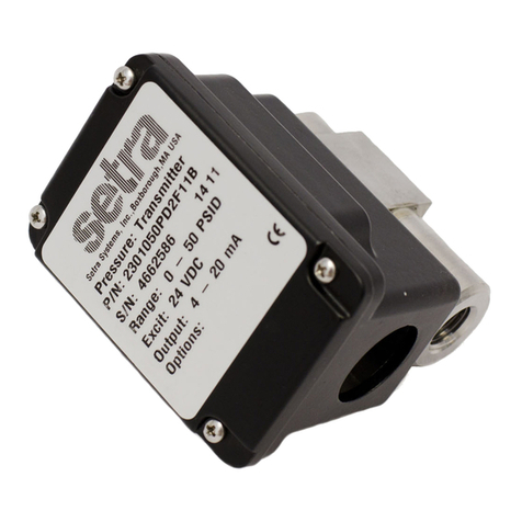
Setra Systems 230 installation guide

Setra Systems

Setra Systems 230 installation guide

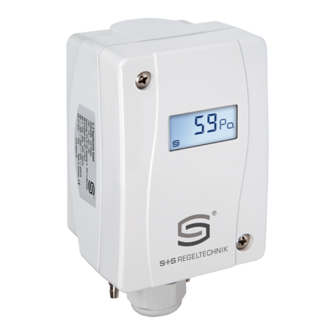
S+S Regeltechnik PREMASGARD 1140 Operating Instructions, Mounting & Installation

S+S Regeltechnik

S+S Regeltechnik PREMASGARD 1140 Operating Instructions, Mounting & Installation

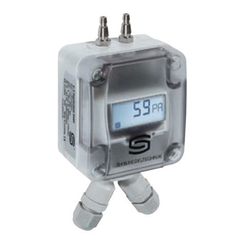
S+S Regeltechnik PREMASGARD 121 Modbus Series Operating Instructions, Mounting & Installation

S+S Regeltechnik

S+S Regeltechnik PREMASGARD 121 Modbus Series Operating Instructions, Mounting & Installation

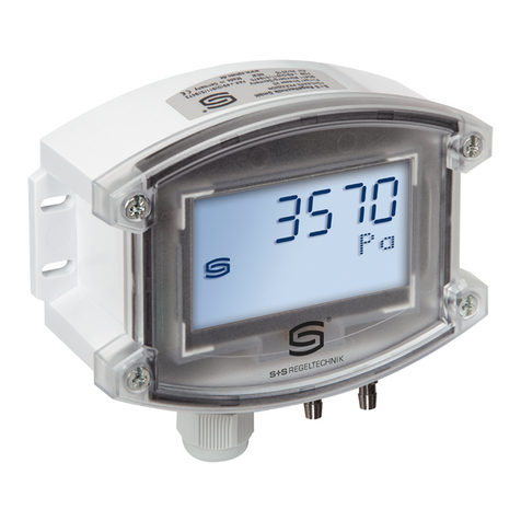
S+S Regeltechnik PREMASGARD 711 Series Operating Instructions, Mounting & Installation

S+S Regeltechnik

S+S Regeltechnik PREMASGARD 711 Series Operating Instructions, Mounting & Installation

manuals.online logo
manuals.online logoBrands
  • About & Mission
  • Contact us
  • Privacy Policy
  • Terms and Conditions

Copyright 2025 Manuals.Online. All Rights Reserved.