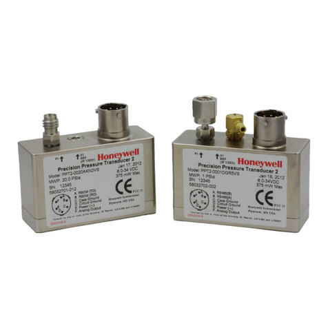
Honeywell PPT User manual

Honeywell Precision Pressure Transducers
PPT and PPTR User’s Manual

ADS-14052, Revision B, 10/16
Email: [email protected]
Web: www.pressuresensing.com
No part of this manual may be reproduced or transmitted in any form or by any means, electronic or mechanical, including
photocopying and recording, for any purpose, without the express written permission of Honeywell, Inc. Honeywell
reserves the right to make changes to any products or technology herein to improve reliability, function or design.
Honeywell does not assume any liability arising out of the application or use of any product or circuit described herein;
neither does it convey any license under its patent rights nor the rights of others.

PPT User’s Manual
Contents
0 USER MANUAL CONTENT ..................................................................................... 1
1 INTRODUCTION ....................................................................................................... 2
1.1 Product Overview ............................................................................................ 2
1.2 Hardware Description .................................................................................... 2
2 GETTING STARTED ................................................................................................. 3
2.1 Overview .......................................................................................................... 3
2.2 Equipment Needed ......................................................................................... 3
2.3 Terminal Program Settings ............................................................................ 3
2.4 Initial Turn-On Response ............................................................................... 4
2.5 Command Format ........................................................................................... 4
2.6 Step-By-Step Examples .................................................................................. 5
2.7 Command Functional Groups ........................................................................ 7
3 COMMANDS - QUICK REFERENCE ...................................................................... 9
4 FUNCTIONAL OPERATION .................................................................................... 13
4.1 Overview .......................................................................................................... 13
4.2 What Is Integration? ....................................................................................... 14
4.3 Pressure Reading Control ............................................................................... 14
4.4 Output Voltage Control ................................................................................... 16
4.5 Pressure Window Control ............................................................................... 16
4.6 Customized Pressure Range ........................................................................... 17
4.7 Setting Pressure Set Points ............................................................................ 18
4.8 PPT Analog Output Configurations ............................................................... 19
4.9 Command Illustrations ................................................................................... 20
4.10 Pressure Reading Decimal Position ............................................................... 24
4.11 PPT Addressing ............................................................................................... 25
i

PPT User’s Manual
Contents (cont’d)
5 COMMANDS .............................................................................................................. 28
5.1 Command Format ........................................................................................... 28
5.2 Information Request Commands ................................................................... 29
5.3 Action Directing Commands ........................................................................... 29
5.4 Command Replies—General .......................................................................... 29
5.5 ASCII Format Replies ..................................................................................... 30
5.6 Binary Format Replies ................................................................................... 31
5.7 Command And Reply Sequencing .................................................................. 34
5.8 Command Errors ............................................................................................. 35
5.9 Command Summary Table ............................................................................. 37
5.10 Command Descriptions ................................................................................... 39
6 ELECTRICAL CONNECTIONS ................................................................................ 73
7 TIMING DIAGRAMS ................................................................................................. 75
8 SPECIFICATIONS ..................................................................................................... 78
9 DIMENSIONS ............................................................................................................ 80
ii

Figure 4.1
Figure 4.2
Figure 4.3
Figure 4.4
Figure 4.5
Figure 4.6
Figure 4.7
Figure 4.8
Figure 4.9
Figure 4.10
Figure 4.11
Figure 4.12
Figure 4.13
Figure 4.14
Figure 4.15
Figure 4.16
Figure 4.17
Figure 4.18
Figure 4.19
Figure 4.20
Figure 4.21
Figure 5.1
Figure 5.2
Figure 6.1
Figure 6.2
Figure 6.3
Figure 6.4
Figure 6.5
Figure 7.1
Figure 7.2
Figure 7.3
Figure 7.4
Figure 7.5
Figure 7.6
Figure 9.1
Figure 9.2
Figure 9.3
Figures
PPT Block Diagram .......................................................................................... 13
Pressure Reading Control ................................................................................ 15
Factory Set Output Levels ............................................................................... 16
User Modified Output Levels ........................................................................... 17
User Modified Pressure Span .......................................................................... 17
Custom Slope (X=) Options .............................................................................. 17
Custom Offset (Z=) Options ............................................................................. 17
Pressure Set Point Set ..................................................................................... 18
Deadband on Set Point ..................................................................................... 18
PPT Pressure to Analog Voltage ...................................................................... 19
PPT Pressure Readings and Analog Voltage Control ..................................... 19
Sensing Remote Analog Pressure .................................................................... 19
Integration (I=) Command, Example 1 ........................................................... 20
Integration (I=) Command, Example 2 ........................................................... 21
S2 Speed Shift Command Example ................................................................. 21
S5 Speed Shift Command Example ................................................................. 22
Deadband and Integration (DI) Command Examples ........................... 22 – 23
Idle Count (IC) Command Example ................................................................ 23
Synchronize Integration Cycles (SI) Command Example .............................. 24
RS-232 PPT Ring Network .............................................................................. 25
RS-485 PPT Multidrop Network ..................................................................... 26
Single PPT Command and Reply .................................................................... 34
Multiple PPT Network Command and Replies ............................................... 35
PPT Electrical Connector Pin Assignments .................................................... 73
Connection for RS-232 Operation and Analog Output ................................... 73
Connection for RS-485 Operation and Analog Output ................................... 74
Connection for Analog Output and Battery Operation ................................... 74
Connection for Computer Operation and
User Controlled Analog Voltage Output ...................................................... 74
Default Single Pressure Reading Timing Diagram ........................................ 75
Default Continuous Pressure Reading Timing Diagram ................................ 75
Continuous Pressure (with IC = 1) Timing Diagram ...................................... 75
Timing Diagram for 20 Readings Per Second ................................................. 76
Timing Diagram for 50 Readings Per Second ................................................. 76
Timing Diagram for 120 Readings Per Second ............................................... 76
PPT Case Outline ............................................................................................. 80
Electrical Connector ......................................................................................... 80
PPTR Case Outline .......................................................................................... 81
iii

Table 1.1
Table 4.1
Table 4.2
Table 5.1
Table 5.2
Table 5.3
Table 5.4
Table 5.5
Table 7.1
Table 7.2
Table 9.1
Table 9.2
Table 9.3
Tables
Various Digital and Analog Output Modes ........................................................... 2
PPT to PPT Remote Sensing Setup Commands ................................................. 20
Decimal Place Locations for Pressure Readings ................................................ 24
Header Description for Binary Format Pressure Readings .............................. 31
Binary Format Character Codes ......................................................................... 33
Command List ..................................................................................................... 37
Command Factory Default List .......................................................................... 39
Display Units Options ......................................................................................... 47
Transmission Times at Selected Baud Rate ....................................................... 77
Number of Bytes in Various Replies ................................................................... 77
ASCII Conversion Table ...................................................................................... 81
RS-232 Standard Pin Connections ..................................................................... 81
Electrical Signal Levels ....................................................................................... 81
iv

0USERS MANUAL CONTENT
This user’s manual is divided into the following sections.
Section 1 Introduction—Product overview and hardware description.
Section 2 Getting Started—Lists equipment and procedures necessary to operate the PPT
and provides a few simple command examples, which will get first-time users
acquainted with the command structure.
Section 3 Commands: Quick Reference—A brief description of each command with
typical PPT input and response examples.
Section 4 Functional Operation
Section 5 Commands—Contains a detailed description of the command structure, func-
tional groupings and all user commands.
Section 6 Electrical Connections—Contains wiring diagrams for various PPT electrical
connections.
Section 7 Timing Diagrams—Illustrates RS-232 serial port timing for command and
reply interaction.
Section 8 Specifications—Contains electrical and environmental specifications.
Section 9 Dimensions—Contains a case outline of the PPT
It is suggested that the first-time user read the “Getting Started” section to be sure the necessary
items are on hand. PPTs are available in various pressure ranges for absolute, gauge and differential
modes of operation. Be sure to connect a source of pressure that matches the transducer range and mode.
1

1INTRODUCTION
1.1 PRODUCT OVERVIEW
The Honeywell Model PPT and PPTR Precision Pressure Transducers (PPT) provide high accuracy
pressure readings in both digital and analog form. The first-time user will be able to use the PPT
within minutes, yet capability exists to configure the PPT for optimum performance in specific
applications. Throughout this User’s Manual, both the PPT and PPTR will be referred to as PPT
(Precision Pressure Transducers) unless the specific model number is stated.
The heart of the PPT measuring system is a silicon piezoresistive sensor which contains both pres-
sure and temperature-sensitive elements. Digital signals representing temperature and pressure are
processed by a microprocessor to produce fully temperature compensated and calibrated pressure
readings over the entire -40 to 85 °C temperature range. The output modes are shown in Table 1.1.
The PPT receives commands and sends data from either a RS-232 port or a multidrop RS-485 port.
Using the RS-232 type PPT, up to 89 units can be connected in a ring configuration to a single serial
port of a computer. The RS-485 type PPT allows up to 89 PPTs to be connected to a two-wire
multidrop bus, when bus repeaters are used to satisfy the RS-485 bus electrical requirements. Group
(multicast) addressing allows up to nine groups of PPTs to be addressed with a single command.
Global (broadcast) addressing will send a command to all PPTs on the serial bus. Any computer
having a serial port and terminal emulation software can be connected to the PPT to allow the user
to select baud rates, sample rates, readout resolution, units of pressure and other choices.
Analog output from the 12-bit digital-to-analog converter may be obtained without a host computer.
User selected functions may be set through the digital interface. The selected functions may either
be used temporarily, until the PPT is powered down, or may be stored in the internal EEPROM to
automatically configure the PPT each time power is applied.
Both the analog and digital outputs are corrected digitally over the full range of -40 to 85 °C. The
PPT has a typical accuracy of 0.05% of full scale (FS) and the PPTR has a typical accuracy of 0.10%
FS. Note that full scale for a 20 psig and a 20 psia is 20 psi, but for a 20 psid it is 40 psi. This is
important to note when determining the accuracy allowance.
Digital Output
Single or Continuous Pressure Readings
Single or Continuous Temperature Readings
Single or Continuous Remote PPT Values
Analog Output
Single Pressure Analog Voltage
Tracking Pressure Analog Voltage
User Set Analog Voltage
Remote PPT Controlled Voltage
Table 1.1—Various Digital and Analog Output Modes
1.2 HARDWARE DESCRIPTION
See Sections 8 and 9.
2

2GETTING STARTED
2.1 OVERVIEW
The first-time user should approach the PPT in a manner analogous to using a word processor
program; i.e., many features are available but one may begin by using those of interest at the mo-
ment. Section 2.7 of this manual lists command features by functional groups to assist in this selec-
tion. When shipped from the factory, the default settings provide a pressure transducer that will be
usable for many applications. Once the user is familiar with the performance and command struc-
ture, changes may be made and stored using the ‘Store Parameters’ (SP) command. Once stored, the
new default settings are activated each time the PPT is powered up. This tailors the personality of
the PPT to meet the needs of a particular application.
2.2 EQUIPMENT NEEDED
To prepare the PPT for operation, three items are needed:
• A mating connector with proper wiring connections (see connector part number and wiring
diagram in Section 6—Electrical Connections);
• A DC power supply;
• A source of pressure that is properly matched to the range and type of the PPT.
To operate the PPT in the analog output mode, one additional item is needed:
• Voltage Output - A five digit voltmeter with 0-5 volt range connected between Analog Out and
Signal Common. A computer is not required when operating in this mode.
To operate the PPT in the digital output mode, one additional item is needed:
• A computer, or host processor, having an RS-232 or RS-485 serial port and terminal program
software such as PROCOM™, VERSATERM™, TERMINAL (Windows®3.x) or
HYPERTERMINAL (Windows®95). These programs are normally used to interface to a modem.
The wiring diagram designates which PPT pins must connect to the computer “send”, “receive”
and “common” pins for proper communications. Some computers may not have an RS-232 or RS-
485 serial port connection identical to the one shown in Section 6, making it necessary to adapt
the PPT connections to that particular computer.
2.3 TERMINAL PROGRAM SETTINGS
• Enter the following settings in the terminal program:
Baud Rate .... 9600
Start Bits .... 1
Data Bits .... 8
Stop Bits .... 1
Parity .... None
• Attach a line feed to the carriage return.
• Turn the local echo ON.
When shipped from the factory, the PPT is set to a baud rate of 9600, 1 start bit, 8 data bits with no
parity and one stop bit. If the baud rate has been subsequently changed, and is unknown, it will be
necessary to search all baud rate values to reestablish communication. See the BP command descrip-
tion in Section 5.10 of this manual for possible settings.
3

2.4 INITIAL TURN-ON RESPONSE
Analog Output
The analog output will provide a voltage (range 0-5V) which, when no pressure is applied to the
PPT, reads:
Voltage Output
Pressure Type
Gauge units
Differential units
Absolute units
Digital Output
(@ zero applied pressure)
0 volt
2.5 volts
A voltage representing atmospheric pressure
Once the wiring connections and terminal program settings are complete, the PPT will automati-
cally send the following response (or similar to) when power is applied. This reply will be gener-
ated any time power is applied to the PPT.
Typical Reply:
RS-232 ?01PPT____10__psid
RS-485 ?00PPT____10__psid
The “?01” or “?00” indicates a default address device called a “null address”. This PPT has not yet
been assigned an ID number so it assumes the null address. The “PPT____10__psid ” indicates a
10 psi differential device.
2.5 COMMAND FORMAT
Any command interaction with the PPT requires electrical connection to the RS-232 or RS-485
serial communications pins. There are two basic types of commands – action directing commands
and information requesting commands. Theses are described in
Commands – Section 5.
Typical PPT commands have the form *ddcc = nnn <cr>
Where: *
dd
cc
=
nnn
<cr>
is the command header character
is the decimal address of the PPT
is a command (refer to Commands – Section 5 for a complete
description of commands)
equal sign (required in some commands)
additional characters (required in some commands)
carriage return is required to end all commands
(do not type, press the ENTER/RETURN key)
4

2.6 STEP-BY-STEP EXAMPLES (Only for single PPT connection)
READ SINGLE PRESSURE
Once the PPT is powered up and connected to a computer, enter the following command:
Type: *00P1 <cr> Response: ?01CP=15.458 (for RS-232)
?00CP=15.458 (for RS-485)
where *
indicates the start of a command
00 is the null address of the PPT (see note below)
P1 is the command to read the most current pressure
Note: The “?” indicates a response from a null address PPT – one which has not been assigned a
device ID. A null address, 00, is coded into each PPT at the factory. When a RS-232 null address
PPT responds, it adds one to its address, hence, the response ‘01’. Refer to the ID command in
Appendix A for a description of addresses and responses.
In the reply, the “01” identifies the individual unit address (range 01-89). The “CP=15.458”
indicates a compensated pressure of 15.458 psi. Your unit may not show this specific reading,
depending on the applied pressure it is measuring.
SET DEVICE ID
To give the PPT an assigned address of 01 up to 89, enter the following commands:
Type: *00WE <cr> This enables the PPT to change a parameter in RAM
Type: *00ID=01 <cr> This sets the null addressed PPT to device ID=01.
Note: The device ID is now used in the command input
Type: *01S= <cr> Response: #01S=00052036 (serial number test)
The “#” now replaces the “?” in the header and indicates the PPT
response is from an address assigned unit.
where: * indicates the start of a command
00 is the null address of the PPT
W E is the command to enable a configuration parameter change
I D is the command to change the device address
01 is the assigned PPT address for this example
S= is the command to read the serial number
READ PRODUCTION DATE
To read the production date, enter the following command:
Type: *01P= <cr> Response: #01P=04/13/95
5

READ CONTINUOUS PRESSURE
For continuous pressure readings at the factory set default rate of 5 per second, enter the follow-
ing command:
Type: *01P2 <cr> This enables a continuous stream of compensated pressure readings
to flow into the terminal program.
Type: $*99IN <cr> This is the best way to stop the continuous pressure reading com-
mands. The ‘$’ character temporarily stops, or suspends, either the
continuous pressure or temperature readings. The *99IN command
stops the continuous pressure readings.
CHANGE TO A NEW SAMPLE RATE
Enter the following command:
Type: *01WE <cr> This enables the PPT RAM to accept a changed parameter.
Type: *01I=M20<cr> This sets the integration time to value 20, which corresponds to an
output sample every 2 seconds.
The sample rate will change to one every 2 seconds. I= is an abbreviation for Integration time
which determines how long to accumulate pressure samples between readings. Each integration
period gathers the data for one pressure reading output (see Section 4.2 What is integration?).
The range of integration times can be set by specifying readings per second (I=R45 for 45 read-
ings/sec) or time delay in 100 millisecond intervals (I=M60 for 6 seconds). The factory set inte-
gration time is 5 samples per second (I=M2).
The output data rate can also be altered by use of the idle count (IC) command or by changing
the reading rate (RR) command in conjunction with the operating mode (OP) command. See
Section 4 for description of these commands.
REPEAT THE READ CONTINUOUS PRESSURE STEP ABOVE
Notice the slower output rate of one sample every 2 seconds.
TRY OTHER COMMANDS
Experiment with other commands to become familiar with the command structures. A short
overview of each command with input and response examples is shown in Section 3 Commands –
Quick Reference. See Section 5—Commands for complete command descriptions. Until an
SP=ALL command is executed, no changes will be stored in the EEPROM. Re-apply the power
or send an IN=RESET command to revert to EEPROM default settings.
6

2.7 COMMAND FUNCTIONAL GROUPS
PRESSURE DISPLAY UNITS PPT reads out psi, in wc, mm Hg, etc.
D U Set pressure units for output readings—any one of 13 common units
U = Specify a user supplied unit of measure
TEMPERATURE
T1 Single °C
T2 Continuous °C
T3 Single °F
T4 Continuous °F
RS-232/RS-485 BUS PARAMETERS
BP Changes baud rate and parity
I D Assign device ID and group addresses
M = Select alternate message Headers [RS-485 only]
SI Synchronize Integration cycles among units [RS-485 only]
TO Set Transceiver Operating parameters
OUTPUT READING AND RATE Speed up or slow down output rate
Single Reading Commands
P1 Single RS-232 pressure reading...ASCII format
P3 Single RS-232 pressure reading...binary format
T1 Single RS-232 temperature reading...°C
T3 Single RS-232 temperature reading...°F
Continuous Readings Commands
P2 Continuous RS-232 pressure readings...ASCII format
P4 Continuous RS-232 pressure readings...binary format
T2 Continuous RS-232 temperature readings...°C
T4 Continuous RS-232 temperature readings...°F
Integration Time Commands —Changes pressure reading response time
DS Set deadband and sensitivity parameters
I = Set pressure integration time, and reading rate
S2 Set threshold level for 2X speed shift
S5 Set threshold level for output within any 50 msec period
SI Synchronize pressure Integration cycles
Idle Count Command —Changes pressure reading response time
I C Set number of idle integration cycles
Reading Response To Changes In Input Pressure—Filters small changes
S2 Set threshold level for 2X speed shift
S5 Set threshold level for output within any 50 msec period
RR Set number of identical readings to skip
OP Transmit all readings or only changed readings
FORMAT PRESSURE READINGS—Changes data length into host processor
Binary Format Commands
P3 Single RS-232 pressure...binary format
P4 Continuous RS-232 pressure...binary format
OP Set operating mode...binary format checksum...set signed or extended binary output
format
ASCII Format Commands
All readings, except P3, P4 and ~, are ASCII format readings.
OP Set operating mode...all readings or only changed readings
7

START-UP PARAMETERS—Sets the PPT configuration after power is applied
WE Enable parameter writes to the RAM or EEPROM
SP Store RAM parameters to the EEPROM for startup
M O Specify the power-up message and operating mode
PRESSURE NOISE REDUCTION—Reduces pressure noise signals
DS Set deadband and sensitivity parameters
ANALOG OUTPUT
D A Enables PPT sensed pressure to control the analog output
N E Enable host computer control of the analog output
N = Supply an analog output value in ASCII format, by host computer
~ Supply an analog output value in binary format, by host computer
H = Set the analog highest reading FS voltage
L = Set the analog lowest reading voltage
O= Set pressure window offset for minimum analog reading
W= Set pressure window width for analog full scale span
A N Turn on or off the customized H=, L=, O=, and W= analog scales
DIAGNOSTIC AND RESET CONTROL
I N Performs a software reset of microprocessor
RS Read status of error indicators
C K Performs and provides the result of EEPROM checksum
OP Use pressure reading checksum for binary format
OFFSET TARE CONTROL
T= Allows user to install an offset in the output reading
TC Turn on or off user controlled tare function
USER AND STARTUP MESSAGES
A= Store 8 characters of user supplied data
B= Store 8 characters of user supplied data
C= Store 8 characters of user supplied data, which can be configured as a watchdog or
reset message
D= Store 8 characters of user supplied data, which can be configured as a watchdog or
reset message
M O Specify the startup header selection
PPT UNIT INFORMATION
P= PPT production date
S= PPT serial number
V= PPT software version number
I D Assign device ID and group addresses
M = Read the maximum full scale pressure limit allowed
CUSTOMIZE PRESSURE WINDOW
F= Customize the full scale pressure limit
O= Set pressure window offset for minimum analog reading
W= Set pressure window width for analog full scale span
X= Set the slope “m” parameter for user input mx+b control
Y= Same as X= but for negative slope in differential device
Z= Set the offset “b” parameter for user input mx+b control
8

3COMMANDSQUICK REFERENCE
Example
Input (1)
Example
Response (2)
A N Analog Range Setting
A= Data String A
Turn analog customization on *01WE
*01AN=ON
Inquiry *01AN
Write string A *00WE
#01AN=ON
(up to 8 characters, a <cr> indicates end-of-
message. More than 8 characters is an invalid write)
(Can store info. such as dates, readings, etc.)
B P Baud Rate and Parity Setting
*00A=2-8-95
Inquiry *00A=
?01A=2-8-95
B= Data String B
Set parameters *99WE
(no parity, 1200 baud) *99BP=N1200
Write string B *00WE
(up to 8 characters, a <cr> indicates end-of-message,
and more than 8 characters will not write to location)
(Can store info. such as dates, readings, etc.)
C K Check EEPROM
C= Data String C
*00B=123.4567
Inquiry *00B=
Inquiry *00CK
?01B=123.4567
?01CK=OK
Write string C *00WE
(up to 8 characters, a <cr> indicates end-of-message,
and more than 8 characters will not write to location)
The C and D string can be used for a watchdog or reset message
*00C=This_is_
(see MO command).
D A Digital and Analog Control
D O Default Operating Parameters
Inquiry *00C=
*00WE
Turn on analog output only *00DA=A
Inquiry *00DA
Set DO parameters *00WE
(factory default setting) *00DO=E
Inquiry *00DO
?01C=This_is_
?01DA=A
?01DO=E0N
D S Deadband and Sensitivity Control
Set DS parameters *00WE
(set deadband to 20 x 0.005% = 0.10%FS ) *00DS=20
Inquiry *00DS
D U Display Units Control
Set DU parameters *00WE
(set units to in. Hg) *00DU=INHG
Inquiry *00DU
D = Data String D
(up to 8 characters, a <cr> indicates end-of-message,Write string D *00WE
and more than 8 characters will not write to location) *00D=A_PPT!!!
The C and D string can be used for a watchdog or reset message
?01DS=00S0
?01DU=INHG
(see MO command).
F = Custom Full Scale Range
Inquiry *00D=
Set F= parameter *00WE
(set custom FS range to 10.5psi) *00F=10.5
Inquiry *00F=
?01D=A_PPT!!!
?01F=10.500
H = Highest Analog Output Voltage
Set H parameter *00WE
(set analog high value to 82% x 5V = 4.2V) *00H=82
Inquiry *00H=
?01H=82
Note: See Section 5.10 for complete command descriptions.
9

I C Idle Count Parameter
Example
Input (1)
Set IC parameter *00WE
Example
Response (2)
(set idle count to 12 , so that 12 output samples are skipped) *00IC=12
Inquiry *00IC
I D Identification Number
Set ID number *00WE
(set device ID of first null addressed unit to 12) *00ID=12
Confirmation of ID=12 *12P1
Set group number *12WE
[RS-232] (set group ID of unit 12 to 95) *12ID=95
[RS-232] Group no. inquiry of device ID=12 *12ID
[RS-485](set group ID of unit 12 to 95 with group sub-address of 01) *12ID=9501
[RS-485] Group no. inquiry of device ID=12 *12ID
I N Initialize PPT Microprocessor
Stop all current operations *99IN
(does not affect RAM data)
Full reset of PPT processor *99IN=reset
Changes to RAM data are lost unless an SP =ALL command
?01IC=12
#12CP= 14.32
#12ID=95
#12ID=9501
was previously issued. (Response is user message, if selected) ?01Pressure_tank_1
I = Integration time
Set I parameter *00WE
(set output rate to 50 readings/second) *00I=R50
L = Lowest Analog Output Voltage
Inquiry *00I=
Set L parameter *00WE
?01I=R050
(set analog low value to 28% x 5V = 1.4V) *00L=28
Inquiry *00L=
M = Maximum Full Scale Value Allowed
(Factory set) Inquiry *00M=
M O Power Up Mode
Set MO parameter *00WE
*00MO=M1
*00WE
Required to save in EEPROM for power-up *00SP=ALL
Inquiry *00MO
N E Digital Input Enable to Analog (DAC) Output
Set a DAC analog output voltage *00NE
(example to set output of DAC to 2.5Volts) *00N=2500
Set continuous PPT DAC parameters *01NE=DAC
(set the PPT#01 DAC output to 2.5Volts) *01N=2500
(set the PPT#01 DAC output to 1.25Volts) *01N=1250
(set the PPT#01 DAC output to 0.1Volts) *01N=100
N = Send Number To DAC
Set N= parameter *00NE
(set analog output value to 4096mV = 4.096V) *00N=4096
Inquiry *00N=
See also the H=, L=, O=, and W= commands to control the analog output
O= Offset Pressure Window For Analog Output
Set O= parameter *00WE
(set pressure offset window to 28% x 20 psi (FS) = 15.6 psi) *00O=28
Inquiry *00O=
Example
?01L=28
?01M=0010psid
?01MO=X2M1
?00N=4096.0
?01O=28
Example
Note: See Section 5.10 for complete command descriptions.
1 0

O P Operating Mode Parameters
Input (1)
Set OP parameter *00WE
Response (2)
(set to extended binary output mode) *00OP=E
Inquiry *00OP
P1 Pressure, Single, ASCII Format
Request compensated pressure *00P1
P 2 Pressure, Continuous, ASCII Format
Request compensated pressure *00P2
P 3 Pressure, Single, Binary Format
Compensated pressure (null address) *00P3
Compensated pressure (assigned address) *01P3
(typical response is a ^ or { char plus 4 data bytes
that are encoded for computer translation)
P 4 Pressure, Continuous, Binary Format
Compensated pressure (null address) *00P4
Compensated pressure (assigned address) *01P4
(typical response is a ^ or { char plus 4 data bytes
that are encoded for computer translation)
P = Production Date
(factory set date, mm/dd/yy) Inquiry *00P=
R R Reading Rate
Set RR parameter *00WE
(skip 5 x 100 = 500 readings if identical) *00RR=5
Inquiry *00RR
RS Read Status
Inquiry *00RS
S2 Speed Shift to 2X
Set S2 parameter *00WE
(shift to double speed if pressure changes *00S2=12
more than 12* 0.01%FS = 0.12% FS)
Inquiry *00S2
S5 Speed Shift at 50msec Intervals
Set S5 parameter *00WE
(Output reading if pressure changes *00S5=60
more than 60 * 0.01%FS = 0.6% FS)
Inquiry *00S5
S I Synchronize Pressure Integration
Synchronize Integration *01SI
SP Store Parameters in EEPROM
Store parameter *00WE
(store all settings stored in RAM in EEPROM) *00SP=ALL
S= Serial Number
Inquiry *00S=
T1 Temperature, Single, °C
Request Celsius temperature *00T1
T 2 Temperature, Continuous, °C
Request Celsius temperature *00T2
T 3 Temperature, Single, °F
Request Fahrenheit temperature *00T3
T 4 Temperature, Continuous, °F
Request Fahrenheit temperature *00T4
?01OP=ANEW
?01CP= 14.450
?01CP= 14.450
(repeated)
^@PSA or
{@PSA
^@P@@or
{@P@@
(repeated)
?01P=04/13/95
?01RR=5
?01RS=0000
?01S2=12
?01S5=60
?01S=00005137
?01CT= 24.5 or ?01CT= ..
?01CT= 24.5 (repeated)
?01FT= 76.1 or ?01FT= ..
?01FT= 76.1 (repeated)
Note: See Section 5.10 for complete command descriptions.
1 1

T C Tare Control Switch
T O Transceiver Operating Parameters
Example
Input (1)
Turn tare control on *00WE
*00TC=ON
Inquiry *00TC
Example
Response (2)
?01TC=ON
T = Set Tare Value
Set RS485 response delay to 2 character times *01WE
*01TO=2
Inquiry *01TO
Set tare value to current pressure reading *00WE
*00T=SET
Set tare value to a % of full scale pressure *00WE
#01TO=M2CN
(set tare to 10% of full scale; 10psi for a 100psi PPT) *00T=0.1
Inquiry *00T=
U = User Supplied Display Units
Set display units *00WE
(set units to 5.1 x psi) *00U=5.100
Activate user display units *00WE
*00DU=USER
Inquiry *00U=
V = Version Number
Inquiry *00V=
W E Write Enable to EEPROM or RAM
Write several RAM parameters *01WE=RAM
(example to set output units to cm water column) *01DU=CMWC
(factory default setting) *01DO=D
(Cancel continuous WE=RAM command) *01WE=OFF
?01T=0.1000
?01U=5.1000
?01V=02.3B6S2V
Note: Any command changes in RAM will be lost when the PPT is powered down unless an SP command saves them to EEPROM.
W= Set Width of Analog Pressure Window
Set W= parameter *00WE
(set pressure window width to 40% x 20 psi (FS)= 8 psi) *00W=40
(set analog set point) *00W=S
X=, Y= Slope - User Compensation Control
Inquiry *00W=
Set X= parameter *00WE
?01W=40
(set user slope control to 0.005% x 17 = 0.085%FS) *00X=17
Inquiry *00X=
?01X=17
Note: The input slope and offset control are for user supplied mx+b correction. The Y= is for negative slope for differential units.
Z= Offset - User Compensation Control
Set Z= parameter *00WE
(set mx+b pressure offset to 20 x 0.005%FS = 0.1%FS) *00Z=20
(null adjust output at zero pressure) *00Z=CAL
Inquiry *00Z=
?01Z=20
~Command Header for Binary DAC Values (Need to set DA=G, N, or R to receive, or O, S, or U to transmit)
Then enable single RAM write for DAC *00NE
(example to set output of DAC to 2.5Volts) ~@#16
See also the H=, L=, O=, and W= commands to control the analog output
(1) A carriage return, <cr>, should follow each input. If the PPT has an established address of 12, for instance, then begin the
command with *12.. instead of *00...
(2) The responses shown here begin with ?01.. and are for a null address PPT. That is, a PPT that has not yet established unit
identification (see ID command). If the PPT has an assigned address of 23, for instance, the response will begin with #23..
instead of ?01...
Note: See Section 5.10 for complete command descriptions.
1 2

4FUNCTIONAL OPERATION
4.1 OVERVIEW
Honeywell’s Precision Pressure Transducer (PPT) is based on a silicon piezoresistive sensor coupled
with a microprocessor and other electronic circuitry. The piezoresistive sensor contains both pressure
sensitive and temperature sensitive elements which, when modeled over a matrix of pressures and
temperatures at the factory, provides a digitally compensated pressure reading. The PPT has a
typical accuracy of 0.05% of full scale (FS) and the PPTR has a typical accuracy of 0.10% FS over a
-40 to +85°C temperature range. This accuracy is achieved by compensation algorithms in the
microprocessor. Because of the internal digital circuitry, having a digital output capability is straight
forward. The digital readings are transmitted via RS-485 signals or RS-232 signals—which are
commonly available on most personal computers. When connected to a computer, the user can modify
the pressure reading rate, integration times, units of pressure, thresholds for deadbands and more.
In addition, a temperature compensated analog output is available. Analog output parameters can be
modified by the user when the PPT digital communications port is connected to a computer, or host
processor. For example, the factory set range of 0 to 5 VDC for the analog output voltage can be
modified to 1 to 5 VDC operation or any voltage span within the 0 to 5 volt range in 1% increments.
Those who choose to use the factory set defaults may use the analog output without ever connecting
to a computer.
The analog output is driven by a 12-bit digital-to-analog converter (DAC). Because the PPT has an
internal EEPROM (Electrically Erasable Programmable Read Only Memory) to store configuration
settings, it can replace conventional analog transducers without connecting to a serial bus. Program
your settings once and use it as a three-wire device—Power, Analog Out, Ground.
Pressure
Input
PPT
Pressure
Sensor
Temperature
Sensor
16 bit
Anaolg
to
Digital
Converter
EEPROM
Micro-
processor
RAM
Voltage Regulator
RS-232 or
RS-485
Driver
12 bit DAC
DC
Power
COM
(Digital
Serial
Data)
0-5V
Output
Figure 4.1—PPT Block Diagram
The PPT can be tailored to specific application requirements. Configuration information is sent to, or
read from, the PPT by user command messages over the serial port. Any configuration parameter
that can be changed by a command may be retrieved by use of that same command. Commands used
to change parameters must be preceded by an enabling command (WE or NE), but commands used
to retrieve information do not require an enable. All configuration changes are stored in the PPT
RAM for immediate use until power is removed. These configuration changes are only made perma-
nent in the EEPROM when the user executes the Write Enable (WE) command followed by the
EEPROM Store Parameters (SP) command. Exceptions to this are the A=, B=, C=, and D= com-
mands which are immediately stored to EEPROM if preceded by the WE command.
1 3

4.2 WHAT IS INTEGRATION?
The input pressure is converted to an analog electrical signal at the pressure sensor. This signal
feeds into a delta-sigma analog-to-digital (A/D) converter where it is changed into a digital signal
representing the pressure value. During the A/D conversion cycle, the signal is integrated over time.
That is, the pressure reading is averaged (integrated) over the A/D conversion cycle so the resultant
digital value is the summation of the average pressures observed during the cycle. This conversion
cycle is controlled by the user with the Deadband and Sensitivity (DS), Synchronization Integration
(SI), Idle Count (IC), and Integration (I=) commands.
4.3 PRESSURE READING CONTROL
The PPT commands allow considerable flexibility in tailoring pressure acquisition times, sample
windows, thresholds, and output rates. These are controlled by 7 commands: Deadband and Sensitiv-
ity (DS), Integration (I=), Speed shift (S2), Speed shift at 50msec intervals (S5), Idle Count (IC),
Reading Rate (RR), and OPerating mode (OP). Figure 4.2 illustrates how the user may control these
attributes in three ways:
First, the internal analog-to-digital converter integration time may be controlled over a range of 1
sample every 12 seconds up to 120 samples per second. This is controlled using the ‘Integration’ (I=)
command. The integration time is used to control the A/D integration cycle that allow noisy pressure
inputs to be filtered, or averaged, over a selected period of time. See Figures 4.12and 4.13. The
integration time can be set within a range of 1 to 120 samples/sec using the I=Rn form or a range of
100msec to 12 sec/sample using the I=Mn form. The values for ‘n’ range from 1 to 120 for both the
rate (Rn) form and the millisecond (Mn) form.
The speed shift commands can only be enabled when the integration time is set using the I=Mn
form. When enabled, the thresholds for pressure change can be set that cause the output rate to
double (S2) or update at 50 msec intervals (S5). When the change of input pressure reaches or
exceeds the threshold, the sample rate shifts to the higher rate.
Second, the integration cycles may be spaced with idle periods that cause pressure reading times to
increase to as often as one every 51 minutes. The Idle Count (IC) command will insert, or skip, from
0 to 255 idle periods equal to the integration time. If the integration time is set to the maximum, 12
sec/sample, and an idle count of 255 is selected, then the time between samples = 12 sec. x 256 = 51.2
minutes.
Third, the reading rate may be controlled so pressure readings are obtained only when pressure
changes occur. The Reading Rate (RR) command can be set to output only changed readings, or skip
from 100 to 1000 identical readings. The Operating Mode command (OP) can be set to output every
reading or to only output changes. The Deadband setting in the DS command can filter a small
pressure change by not allowing the pressure reading to vary as long as it remains within the
deadband limits. This controls the sensitivity to change of the RR and OP command modes when the
‘output only when pressure changes’ options are selected. If the pressure signal is stable within the
deadband limit, then the pressure reading time can be increased up to 1000 times the integration
time by using the RR command.
1 4
This manual suits for next models
1
Table of contents
Other Honeywell Transducer manuals
Popular Transducer manuals by other brands

SIAP+MICROS
SIAP+MICROS t027 TP200 User manual and maintenance

Thyracont
Thyracont VCC200MA4 operating instructions

CONTINENTAL CONTROL SYSTEMS
CONTINENTAL CONTROL SYSTEMS WattNode Pulse Quick install guide

ALEKTO
ALEKTO E855A Operation manual

Balluff
Balluff BTL5-S1 Series Condensed guide

HBM
HBM C18 Mounting instructions

M-system
M-system L2PA instruction manual

novotechnik
novotechnik TM1 Series user manual

TR-Electronic
TR-Electronic LMP-30-300 PB manual

S+S Regeltechnik
S+S Regeltechnik PHOTASGARD FSHKM Operating Instructions, Mounting & Installation

Baumer
Baumer BMMS K Assembly instruction and safety information

Panametrics
Panametrics T5 installation guide