Pure Fitness 8536DT User manual

Pure Fitness Dual Trainer
Model No. 8536DT
Owner’s Manual
Please read all the instructions before using this product.
Consult a physician before beginning any exercise program or strenuous activity
Do not allow more than one person on the trainer at any time.
ADULT ASSEMBLY REQUIRED.
To ensure warranty coverage, please visit www.pureglobalbrands.com
to register your product
Pure Fitness is a Trademark of
Pure Global Brands, Inc.
The contents of this
package are not suitable
for children under 3 years.
Contains small parts which
may cause choking.

OWNERS MANUAL
CUSTOMER SERVICE INFORMATION
Thank you for purchasing our Pure Fitness™ Dual Trainer.
At Pure Global Brands, we want all of our customers to be completely satised with their purchase.
Please take time to review the contents of the product you just received to make sure that all of the
parts are included. If you nd that any parts are missing or damaged, we will happily provide replace-
ment parts at no charge within 30 days of purchase. Please keep in mind that for select damaged part
replacement requests, we will require a photo for submission to our quality control ofce.
To order these parts, or if you have any other questions or concerns about this Pure Global product,
please e-mail the Pure Global Brands, Inc. customer service department at:
[email protected] or contact us at 1-866-498-5269.
You can also visit our website at: www.pureglobalbrands.com
If you request replacement parts, please be sure to include the following information in your corre-
spondence:
YOUR NAME
YOUR MAILING ADDRESS
YOUR EMAIL ADDRESS
RETAILER WHERE YOU PURCHASED PRODUCT
DATE OF PURCHASE
ORDER # (IF AVAILABLE)
PRODUCT MODEL #: 8536DT
SERIAL #
PRODUCT NAME: Pure Fitness Dual Trainer
PART # (located in manual)
QUANTITY NEEDED
PICTURE OF DAMAGED PART(s) – SUBMIT VIA Email , Fax, or Mail
Again, thank you for purchasing a Pure Global Brands product.
Sincerely,
Customer Service
Pure Global Brands, Inc.
8040 Belvedere Road
West Palm Beach, FL 33411
1-866-498-5269

LIMITED WARRANTY
Pure Global Brands, Inc. warrants this product to be free from defects in workmanship and materials
under normal use and conditions for the duration of the period outlined below FROM THE DATE OF
ORIGINAL PURCHASE. This Limited Warranty is not transferable and is available only for the origi-
nal purchaser of the Product.
The various components of this equipment are warranted against defects and workmanship for the
following time period(s):
• Steel Frame 1-year.
• All Other Parts 90-Days
All warranty coverage extends only to the original retail purchaser from the date of purchase.
Pure Fitness’s obligation under this Warranty is limited to replacing or repairing, at Pure Fitness’s
option, the product at one of its authorized service centers. All products for which a warranty claim
is made must be received by Pure Fitness at one of its authorized service centers and accompanied
by sufcient proof of purchase (photocopy of the original store receipt, indicating the date of pur-
chase). All freight and handling fees are the responsibility of the consumer to pay, both to and from
Pure Fitness. All warranty claims must be pre-authorized by Pure Fitness. Pre-authorization can be
obtained by calling 866-498-5269. This warranty does not extend to any product or damage to a
product caused by or attributable to freight damage, abuse, misuse, improper or abnormal usage, or
repairs not provided by a Pure Fitness authorized service center or for products used for commercial
or rental purposes. This warranty does not cover ordinary wear and tear, weathering, failure to follow
directions, improper installation, improper maintenance, or acts of Nature (such as damage caused
by wind, lightning, snow, water, or ice). Weather damage, damage caused by unauthorized repair
work or damage caused by improper use of the products are not covered by the product warranty. No
other Warranty beyond that specically set forth above is authorized by Pure Fitness.
PURE FITNESS IS NOT RESPONSIBLE OR LIABLE FOR INDIRECT, SPECIAL OR
CONSEQUENTIAL DAMAGES ARISING OUT OF OR IN CONNECTION WITH THE
USE OR PERFORMANCE OF THE PRODUCT OR OTHER DAMAGES WITH RESPECT
TO ANY ECONOMIC LOSS, LOSS OF PROPERTY, LOSS OF REVENUE OR PROFITS,
LOSS OF ENJOYMENT OR USE, COST OF REMOVAL, INSTALLATION OR OTHER
CONSEQUENTIAL DAMAGES. SOME STATES DO NOT ALLOW THE EXCLUSION OR
LIMITATION OF INCIDENTAL OR CONSEQUENTIAL DAMAGES. ACCORDINGLY, THE
ABOVE LIMITATION MAY NOT APPLY TO YOU. THE WARRANTY EXTENDED HERE-
UNDER IS IN LIEU OF ALL OTHER WARRANTIES AND Pure Fitness SPECIFICALLY
DISCLAIMS ANY IMPLIED WARRANTY OF MERCHANTABILITY OR FITNESS FOR A
PARTICULAR PURPOSE IS LIMITED IN ITS SCOPE AND DURATION TO THE TERMS
SET FORTH HEREIN. SOME STATES DO NOT ALLOW LIMITATION ON HOW LONG
AN IMPLIED WARRANTY LASTS. ACCORDINGLY, THE ABOVE LIMITATION MAY
NOT APPLY TO YOU.
This warranty gives you specic legal rights. You may also have other rights, which vary from state to
state.

WARNING
CHOKING HAZARD – Small parts
NOT for children under 3 years.
Warning
While every attempt is made to ensure the highest degree of protection in all
equipment, we cannot guarantee freedom from injury. The user assumes all risks
of injury due to use. All merchandise is sold on this condition, which no
representative of the company can waive or change.

WARNING
IMPORTANT – PLEASE READ!
PRIOR TO ASSEMBLING:
Please visit: www.pureglobalbrands.com for any important product information updates
and/or additional safety warnings before assembling or using this product.
Use search word: 8536DT
WARNINGS – GENERAL SAFETY ADVICE
Please read these instructions in their entirety before use and retain for future reference.
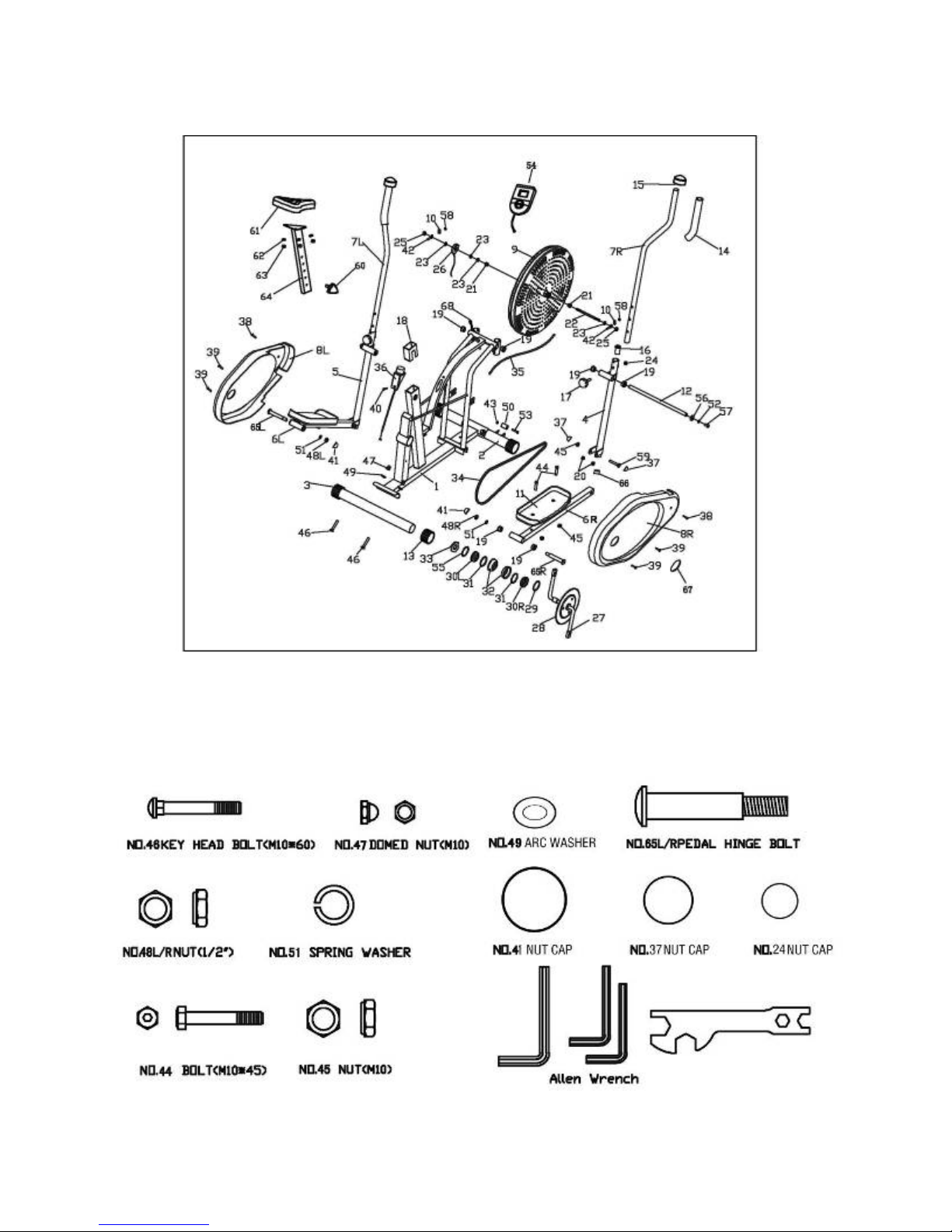
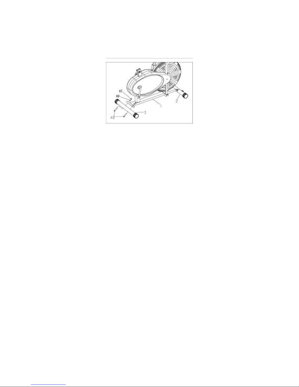
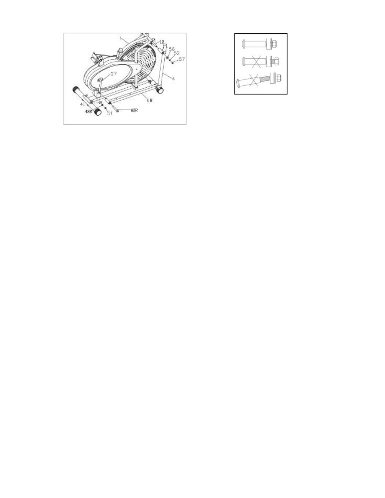
● Ensure that this product has been assembled correctly, per the instructions in the manual.
● This manual is designed to help you assemble, adjust, maintain and use the product. It contains
important information regarding your safety and your use of this equipment.
● ALWAYS check this product before each use for missing or loose bolts and damaged parts.
Carefully inspect pedals, handle assemblies and the resistance belt on the fan wheel to check for
damage or signicant fraying and ensure the seat is secure in its housing.
● ALWAYS ensure that the wheel and pedal assemblies move freely and do not exhibit any obvious
signs of distress by testing the moving parts on this unit before beginning an exercise.
● NEVER make or attempt to make any modications or repairs to this product.
● ALWAYS hold the Handles when mounting and dismounting this product to prevent the pedals
from accidentally moving when you are securing your feet in position or sitting down on the seat.
● NEVER attempt to suddenly stop pedaling or switch the direction of pedaling while moving, as
serious injury and/or severe damage to the unit can occur, for which Pure Global is not liable.
● ALWAYS consult a physician before beginning any exercise program. Ask your doctor to evaluate
your present tness level and determine the exercise program that is most appropriate for your
particular age and/or physical condition.
● IF YOU EXPERIENCE any pain or tightness in your chest, irregular heartbeats, shortness of
breath, faintness, dizziness, or other unusual discomfort while exercising, STOP and immediately
consult your physician and/or obtain medical assistance.
● This machine is intended for indoor individual home use only, it is not designed for commercial use
or for use in communal workout areas.
● DO NOT allow children or pets to use, climb on, or play near this product.
● NEVER allow more than one person at a time on this product.
● Ensure that the product is on level ground. If necessary, use a rubber mat under the machine to
reduce the possibility of slipping during use.
● Warm up at least 5-10 minutes before each workout and to cool down for at least 5-10 minutes
afterwards.
● NEVER hold your breath while exercising.
● Rest adequately between workouts to allow your muscles to tone and develop.
● DO NOT wear loose tting clothing, belt buckles, or jewelry, including but not limited to rings,
chains, and pins before commencing exercise; this can be extremely dangerous.
● DO NOT stand or kneel on the seat.
● ALWAYS wear the appropriate tness footwear. DO NOT use this product barefooted or with
socks only. If applicable, ensure that any shoe laces will not become caught in moving parts.
● NEVER exceed the MAXIMUM WEIGHT LIMIT of 220LBS (100KGS)
● Dispose of all packaging materials safely and per local ordinance.
● Please retain this information for future reference.

8536DT EXPLODED VIEW

8536DT PARTS LIST
NOTE: For your convenience, your Dual Trainer has been pre-assembled. Many of
the items on this list are for troubleshooting and parts identication ONLY, and
will not be needed for assembly.
No. Description Qty No. Description Qty
1Main Frame 1 34 Chain 1
2Front tube 1 35 Tension belt 1
3Rear tube 1 36 Tension control 1
4Right coupler bar 1 37 Nut cap M10 4
5Left coupler bar 1 38 Phillips Screw 1
6L Left pedal tube 1 39 Phillips Screw 1
6R Right pedal tube 1 40 Head screw 1
7L Left handlebar 1 41 Nut cap M12 2
7R Right handlebar 1 42 Tighten screw 2
8L Left housing 1 43 Safety Nut M6 2
8R Right housing 1 44 Allen Screw 4
9Fan wheel 1 45 Safety Nut 4
10 U shape block 2 46 carriage bolt 4
11 Pedal 2 47 Cap nut 4
12 Axle 1 48L Safety Nut 1
13 End cap for foot tube 4 48R Safety Nut 1
14 Foam 2 49 Arc washer 4
15 End cap for handlebar 2 50 Roller 2
16 Plastic bushing 4 51 Washer 2
17 Bolt 2 52 Washer 2
18 Plastic bushing 1 53 Allen Screw 2
19 Plastic bushing 1 10 54 Computer 1
20 Plastic bushing 2 4 55 Stop washer 2
21 Steel bushing 2 56 D shaper washer 2
22 Fan wheel axle 1 57 Allen Bolt 2
23 Nut 3 58 Allen Nut 2
24 Nut cap M8 2 59 Allen Screw 2
25 Nut 2 60 Know 1
26 Sensor 1 61 Saddle 1
27 Crank 1 62 Washer 3
28 Chain-plate 1 63 Safety Nut 3
29 Washer 1 1 64 Adjustable tube for saddle 1
30L Collar bushing left 1 65L bolt for pedal(left) 1
30R Collar bushing right 1 65R bolt for pedal(right) 1
31 bearing 2 66 End cap 2
32 Collar housing 2 67 Phillips Screw 2
33 Nut 1 68 Sensor Wire 1

STEP 1: ASSEMBLE FRONT AND REAR STABILIZERS
Locate 4x M10 Dome Nuts (47), 4x Arc Washers (49), 4x M10x60 Bolts (46), the Front Stabilizer Bar
with Wheels (2), and the Rear Stabilizer Bar (3)
A. Position the Front Stabilizer Bar with Wheels (2) under the Fan Wheel of the bike and align the
bolt holes to the frame.
IMPORTANT: When aligning these holes, make sure the dimpled, square openings in the Bar are
facing down towards the ground.
B. Attach the Stabilizer Bar to the Main Frame by inserting the bolts up through the Bar. Secure the
bolts rst with the Arc Washers and then tighten the Cap Nuts down to this assembly.
C. Position the Rear Stabilizer Bar (3) behind the Main Frame and attach this to the Main Frame as
described in Section B above.
8536DT ASSEMBLY INSTRUCTIONS
NOTE: The following instructions use the included tools:
Multi-Hex Tool, Small Allen Wrench, and Large Allen Wrench.
Please locate these and keep on hand to assemble.

STEP 2: ATTTACH HANDLE AND PEDAL ASSEMBLIES
Locate 2x M10x18 Bolts (57), 2x Spring Washers (52), 2x D Washers (56),
1x Rotation Rod (12), Left Hand Rail/Left Foot Bar (5, 6L), Right Hand Rail/Right Foot Bar (4, 6R),
and the Left Pedal Assembly (41, 48L, 51, 65L) and the Right Pedal Assembly (41, 48R, 51, 65R).
A. Place the Rotation Rod (12) through the hole in the front of the Main Frame above the Fan Wheel.
Slide the Left and Right Hand Rails (4, 5) onto the exposed ends of the Rotation Rod.
1. Assemble the RIGHT Upper Handrail (4) to the Rotation Rod (12) with the hardware in the following
order: 1st: 1x D Washer (56), 2nd: 1x Spring Washer (52) and Secure with 1x M10x18 Bolt (57).
2. Assemble the RIGHT Upper Handrail to the Rotation Rod with the hardware in the same order.
B. Once the Upper Hand Rails have been secured, Attach the Lower Foot Bars (6L, 6R) to the Pedal
Crank using the Left and Right Pedal Assemblies. The ends of the Crank Bolts (65L, 65R) will be
stamped with a “L” or an “R” indicating which side they are to be used on. Note: The Pedal Assem-
blies are threaded in the same manner as a bicycle pedal, and one will need to be rotated in the op-
posite direction than a normal screw to tighten.
Assemble the RIGHT Lower Handrail (6R) to the Pedal Crank (27):
1. Place a Washer (51) onto the stamped Bolt (65R).
2. Thread this Bolt and Washer through the hole in the Left Lower Foot Bar (6R).
3. Once the Bolt is through, slide a Safety Nut (48R) onto the other end of the Bolt.
4. Screw this assembly (65R, 51, 48R) into the Pedal Crank (27).
5. Secure with the Hex Nut (41) completing the Right Pedal Assembly.
C. Repeat the above steps to attach the Left Foot Bar (6L) using the same Assembly hardware.
In order to install the Stamped Bolt (65) properly, keep it
perfectly straight as the bolt goes through the pedal tubing
and the crankshaft. If the hinge bolt is connected to the
crankshaft at an angle, damage to both the hinge bolt and the
crankshaft may occur.

STEP 3: ASSEMBLE PEDALS AND HANDLE BARS
Locate 2x Foot Pedals (11), 4x M10x45 Bolts (44), 4x M10 Nuts (45), 2x Handle Bars (7L, 7R), and 2x
Lock Knobs (17)
A. Line up the holes on each Foot Pedal to the two holes in the Lower Foot Bar. Thread 2x M10x45
(44) Bolts through each pedal, making sure that the Bolt heads are ush to the Foot Pedal surface.
Secure with 2x M10 Nuts (45).
B. Attach the Handle Bars (7L, 7R) to the Main Frame by sliding them into the top of the
Upper Handrails. Secure this attachment with 2x Lock Knobs (17) as shown. Make sure you screw
the knobs in from the seat side of this attachment.
Note: When attaching the Handle Bars according to Section B, the Trainer is in Elliptical or
Dual-action mode (Handles and Pedals moving). You can also attach the Handle Bars in the two
center posts to achieve a Fixed Mode for use with the bicycle function and to achieve a more
strenuous leg workout.
C. To attach the Handle Bars (7L, 7R) in Fixed Mode. Insert the bars into the two center posts and
secure them with the Lock Knob (17) from the front of the Main Frame.

STEP 4: ASSEMBLE SEAT, MONITOR, AND PLACE DOME COVERS
Locate Seat Cushion (61), Seat Post (64), Seat Adjustment Knob (60) and the Monitor (54).
A. Remove the Hex Nuts and Washers from underneath the Seat Cushion (61). Guide the exposed
bolts on the Seat Cushion underside through the 3 holes in the Seat Post (64). Place a washer
against the plate on the Seat Post and secure with the Hex Nuts.
B. Place the assembled Seat Cushion/Seat Post into the rectangular hole in the top on the unit.
Carefully lower this assembly and secure with the Seat Adjustment Knob (60). Be sure to watch for
pinch points in case the seat suddenly drops. Before continuing, make sure that this assembly is
secure, and the knob is extended through one of the holes in the post.
D. Connect the Sensor Wire (68) to the short wire which extends from the back of the Monitor (54).
Once this connection is secure, slide the Monitor onto the short metal tab in between the Handles
until it locks into place. Make sure that the wires are not contacting any moving parts, and ensure that
this wire will be kept away from the Fan Wheel and the Handle assembly at all times.
E. Once assembly is complete, place a dome cap over in the following areas: The front handle hinges
on 6L, 6R, The welded front side of the Handle Lock Knobs array (17), and over the bolts holding the
rotation rod in place (12).

METER INSTRUCTIONS
FUNCTION BUTTON:
MODE: This button cycles through the available Displays and turns the unit ON. Press and hold this
button for 3-4 seconds to reset the data values of the monitor.
NOTE: When the batteries are replaced, ALL values will reset to ZERO automati-
cally.
FUNCTIONS & OPERATIONS
1. Battery Installation:
This meter takes 2 x AA 1.5V batteries. Install batteries under the cover in the rear of the meter.
Note: Replacing the batteries will reset ALL values on the meter to ZERO.
2. Auto On/Off:
The system turns on when the MODE key is pressed or when you begin to pedal the bike.
The system turns off automatically approximately 4 minutes after you have stopped using the unit.
Display Specications
1. SPEED-------------------------0~99.9 (Speed travelled)
2. CALORIE---------------- 0~99.99 (Calories burned)
3. DISTANCE---------------- 0~99.99 (Distance traveled)
4. SCAN------------------------3 SEC (Displays data (rotating) from all modes)
5. TIME----------------------- 0:00~99:59 (Duration of exercise)
Note:
1. If the computer displays data abnormally, please remove the batteries and try again.
2. Battery Spec: 1.5V AA (2PCS).
3. The batteries must be removed from the appliance before it is scrapped and disposed of per local
ordinance.

USING YOUR DUAL TRAINER
ALWAYS consult a physician before beginning any exercise program. Ask your doctor to evaluate
your present tness level and determine the exercise program that is most appropriate for your
particular age and/or physical condition.
TO USE THE DUAL TRAINER:
Stand on the unit, making sure that each foot is securely positioned on each Pedal and that you have
sure footing on the Pedal pads (Do not use this machine barefoot or with socks only.) Firmly grasp the
Poles in each hand, and using the Poles only, move them back and forth so that the machine begins
to pedal in a forward fashion. Once it is fully in motion, you can begin using your leg muscles to as-
sist in pedaling. It is strongly recommended that you do not attempt to use this machine in a reverse
direction.
You can also mount the Dual Trainer like a bicycle. With your body securely centered on the seat, use
your leg muscles to move the pedals.
NEVER attempt to suddenly stop pedaling or switch the direction of pedaling while moving, as
serious injury and/or severe damage to the unit can occur, for which Pure Global is not liable.
TO INCREASE THE RESISTANCE ON YOUR DUAL TRAINER:
Use the Tension Control Knob to adjust the resistance on the Dual Trainer. Turn the knob towards the
“+” to increase the resistance and “-” to decrease the resistance.
Warm-up
Before every training you should warm-up for 5~10 minutes. Here you can do some stretching and
training with low resistance.
Cool down
To introduce an effective cool-down of the muscles and the metabolism, the intensity should be
drastically decreased during the last 5~10 minutes, but a prolonged exercise session should not be
suddenly and completely stopped. Stretching is also helpful for the prevention of muscle aches.
Training session
The time-length of your training session can be calculated with the following rule of thumb:
Daily training session: approx. 10 min. per unit
2-3 x per week: approx. 30 min. per unit
1-2 x per week: approx. 60 min. per unit

ADJUSTING BELT TENSION
Normal Tension Adjustment:
For normal tension adjustment during use, simply use the Tension Adjustment Knob as mentioned on
the previous page. Turning the adjustment knob allows you to change the tension level and vary the
intensity of your workout as you exercise.
Manual Belt Tension Adjustment:
For manual belt tension adjustment, you can loosen or tighten the friction belt by re-strapping it. To do
so, rst turn the tension adjustment knob to the loosest setting (-). Then re-strap the belt at the buckle
on the top of the fan wheel just beneath the center beam. The more length you allow on the friction
belt the less friction it will have (less tension). Re-adjust the tension knob after you nished
re-strapping. Always try to nd the appropriate tension for your workout using the Normal Tension
Adjustment rst, as manually adjusting the belt tension can require some trial and error to get the belt
tension to your desired resistance.

14
WARM UP EXERCISES
A successful exercise program consists of a warm-up, aerobic exercise, and a cool-
down. Do the entire program at least two and preferably three times a week, resting for
a day between workouts. After several months, you can increase your workouts to four
or five times per week.
Warming up is an important part of your workout, and should begin every session. It
prepares your body for more strenuous exercise by heating up and stretching out your
muscles, increasing your circulation and pulse rate, and delivering more oxygen to your
muscles. At the end of your workout, repeat these exercises to reduce sore muscle
problems. We suggest the following warm-up and cool-down exercises:
Inner Thigh Stretch
Sit with the soles of your feet together
with your knees pointing outward. Pull
your feet as close into your groin as
possible. Gently push your knees towards
the floor. Hold for 15 counts.
Hamstring Stretch
Sit with your right leg extended. Rest the
sole of your left foot against your right
inner thigh. Stretch toward your toe as far
as possible. Hold for 15 counts. Relax and
then repeat with left leg extended.
Head Roll
Rotate your head to the right for one
count, feeling the stretch up the left side
of your neck. Next, rotate your head back
for one count, stretching your chin to the
ceiling and letting your mouth open.
Rotate your head to the left for one count,
and finally, drop your head to your chest
for one count.
Shoulder Lift
Lift your right shoulder up toward your ear
for one count. Then lift your left shoulder
up for one count as you lower your right
shoulder.
WARM UP/COOL DOWN EXERCISES

15
WARM UP EXERCISES CONTINUED
Calf-Achilles Stretch
Lean against a wall with your left leg in
front of the right and your arms forward.
Keep your right leg straight and the left
foot on the floor; then bend the left leg
and lean forward by moving your hips
toward the wall. Hold, then repeat on the
other side for 15 counts
Toe Touch
Slowly bend forward from your waist,
letting your back and shoulders relax as
you stretch toward your toes. Reach down
as far as you can and hold for 15 counts.
Side Stretch
Open your arms to the side and continue
lifting them until they are over your head.
Reach your right arm as far upward toward
the ceiling as you can for one count. Feel
the stretch up your right side. Repeat this
action with your left arm.
WARM UP/COOL DOWN EXERCISES

Question: “How should I clean my Dual Trainer?”
Answer: YOU SHOULD CLEAN THE TRAINER WITH A SOLUTION OF WARM WATER AND
NON-CORROSIVE AND/OR NON-ABRASIVE SOAP. DAMPEN A RAG WITH THIS SOLUTION AND
WIPE COMPLETELY DRY BEFORE USING.
Question: “Is there any maintenance I need to do for my Dual Trainer?”
Answer: YOU SHOULD ALWAYS DOUBLE CHECK TO MAKE SURE ALL YOUR BOLTS ARE
TIGHT AND SECURE, THE ELLIPTICAL POLES AND PEDALS ARE SECURELY ATTACHED, AND
THE MACHINERY IS MOVING FREELY AND SMOOTHLY. IF YOU NOTICE ANYTHING
UNUSUAL ABOUT THE OPERATION OF YOUR MACHINERY, OR FIND ANY MISSING OR
DAMAGED PARTS, CEASE USE OF THE UNIT IMMEDIATELY AND CONTACT CUSTOMER SER-
VICE AT: [email protected] OR BY CALLING 866-498-5269.
Question: “Something was missing from the packaging,” “I need to purchase a replacement part”
or “I discovered a damaged piece. What should I do?”
Answer: CONTACT CUSTOMER SERVICE AT: [email protected] or by calling
866-498-5269. YOU MUST HAVE YOUR PROOF OF PURCHASE AND/OR ORDER
CONFIRMATION AVAILABLE TO BE CONSIDERED FOR WARRANTY REPLACEMENT. YOU
MUST REPORT MISSING PIECES WITHIN 30 DAYS FROM DATE OF PURCHASE. PLEASE BE
AWARE THAT UNDER OUR LIMITED WARRANTY, FOR SOME PARTS WE REQUIRE A PICTURE
OF THE DAMAGED ITEM AND/OR RETURN OF THE DAMAGED ITEM(S) TO OUR QUALITY
CONTROL OFFICE FOR REVIEW.
FREQUENTLY ASKED QUESTIONS
Table of contents
Popular Elliptical Trainer manuals by other brands

Pro-Form
Pro-Form 105 CSE user manual

Life Span
Life Span X-17 owner's manual

Pro-Form
Pro-Form 400 Zle Elliptical Gebruiksaanwijzing

Pro-Form
Pro-Form PFEL64907.0 user manual

Pro-Form
Pro-Form 800 Hr Heart Rate Control Elliptical Bedienungsanleitung

HEALTH RIDER
HEALTH RIDER H82e Elliptical Manuel de l'utilisateur

Pro-Form
Pro-Form PFEVEL96107.0 user manual

Pro-Form
Pro-Form PFIVEL86174.0 user manual

Healthstream
Healthstream HS 3.2 EL user manual

Pro-Form
Pro-Form 505 Zle Elliptical Bedienungsanleitung

Pro-Form
Pro-Form CardioCross Trainer 831.285371 user manual

Pro-Form
Pro-Form 480 Spacesaver Elliptical Bedienungsanleitung