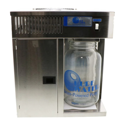
Pure Water PTSF-2510-10 User manual

For Model
• PTSF-2510-10
• PTSF-2510-13
Owners Manual
Installation Instructions

Subject Page
PURE TECH 2500 Diagram 3
Job Specification Sheet 4
SystemOverview 5
PreInstallation 6
Installation 7
Installing Drain line 9
Turning Water Back On 10
PostInstallation 11
InformationNotes 11
Maintaining Your System 12
Installing Chlorine in PURE TECH 250 13
Backwash Start up Procedure 14
TimerAssembly 16
TimerPartsList 17
Control Valve Drive Assembly 18
ControlValveDrivePartsList 19
Control Valve Base Assembly 20
Control Valve Base Parts List 21
Bypass Valve Assembly, Plastic 22
Bypass Valve Assembly, Brass 23
Troubleshooting 24
Seal and Spacer Replacement 25
PURE TECH 250 FEATURES 27
Installation for PURE TECH 250 28
Chlorine Manufacturers 29
Warranty 30
Notes 31
Tech Support: 1-888-989-7873
PURE WATER TREATMENT, INC.
Page 2
Table of Contents
P.O. Box 730486
Ormond Beach, FL 32173-0486
1-888-989-(PURE) 7873 Office • 1-877-219-(PURE) 7873 Fax
Copyright© 2003 all rights reserved

Page 3
Figure A
PURE TECH 2500 FLOW DIAGRAM
PURE TECH 2500
TO DRAIN
CLEAN WATER
2ND BALL VALVE
1ST BALL VALVE
SPIGOT
PURE TECH 250
PRESSURE TANK
PUMP
RAW WATER

Tech Support: 1-888-989-7873
PURE WATER TREATMENT, INC.
Page 4
• JOB NO. _________________________________________________________
• MODEL NO. ______________________________________________________
• WATER TEST _____________________________________________________
• MINERAL TANK SIZE DIA. _______ HEIGHT ________
• CONTROL VALVE SPECIFICATIONS:
Type of Timer
A) Std C) 7 Day
B) *L* D) 12 Day
Day/Time of Backwash
Drain Line Flow Control _____________ gpm
Injector Size _______________________
TYPICAL CONTROL VALVE INFORMATION
Job Specification Sheet
Tank
Dia.
Injector Inj.
Color
Slow Rinse Rate (gpm) DLFC
***
6” #0 Red .31 gpm 1.2 gpm
7” #0 Red .31 gpm 1.2 gpm
8” #1 White .45 gpm 1.5 gpm
9” #1 White .45 gpm 2.0 gpm
10” #1 White .45 gpm 2.4 gpm
12” #2 Blue .84 gpm 3.5 gpm
13” #2 Blue .84 gpm 4.0 gpm
14” #3 Yellow 1.0 gpm 5.0 gpm
16” #3 Yellow 1.0 gpm 7.0 gpm
Due to varying water conditions, tank sizes and water pressures, the above settings
should be used only as a guideline.
*** D.L.F.C. (Drain Line Flow Control). Backwash and Rapid Rinse Flow Rates.

Tech Support: 1-888-989-7873
PURE WATER TREATMENT, INC.
Page 5
• This installation guide gives a step by step, start to finish procedure for installing
PURE TECH 2500 systems using Fleck valves.
• Your new system from the PURE WATER TREATMENT, INC. comes with an
owner/service manual, which, is enclosed along with these instructions, and will help
explain all necessary details required for successful installation and operation of your
system. Please refer to these instructions and the service manual supplied with your
system during installation and programming.
• All steps provided herein are for typical installations only. If you require additional
plumbing to install your system, simply contact a person who is knowledgeable in
residential plumbing or have a local plumbing company help you install, or install the
system for you.
• There is a bit of "over-kill" in our instructions, but please bear with us as we want to
ensure that you, our customer, fully understand the instructions and are completely
satisfied with your installation!
• We recommend that you take a few minutes and look at the service/parts manual for
your particular model, to help you better understand your new water system. Take
your time and carefully read the instructions.
• Get all of your plumbing parts together before you start, and have an assistant help
you, if possible. Typical installation should take no more than a few of hours.
• If you are going to turn the water off to your house while installing the system, we
recommend that you turn off the electricity to your electric water heater during instal-
lation. After the system is installed with water running through it, turn on a few hot
and cold-water faucets, and let them run until there is no more air in your lines, then
turn the electricity back on to your water heater.
• Our systems can safely handle a pressure range of 35-95 psi. However, as with most
residential plumbing and for best operation causing the least wear on critical parts, we
recommend an operating range of 40-65psi. Now all you have to do is plumb in the
system, plug it in and set the current time of day!
System Overview

Tech Support: 1-888-989-7873
PURE WATER TREATMENT, INC.
Page 6
• Your system should be located in a protected, dry, level and non-freezing area.
• We recommend a ½" drain for the backwashing cycles. If possible, the house drain
should be no farther than 20 feet from the system. (Always follow local plumbing
codes).
• You will need a standard 3-prong, 120V, grounded outlet that is not controlled by a
switch. Our Fleck valves have a 5' power cord, but you can use an extension cord if
an outlet is not nearby. Please follow any local building/safety codes if you need to
use an extension cord.
• Make a list of all the plumbing fittings you will need to completely install the system
to make it ready for operation.
• Assemble all tools needed to install the system, and start your installation!
Tools and Materials needed
1) Pipe Cutters
2) PVC Glue
3) PVC, copper or CPVC pipe
4) Two 1” or ¾” male adapters—Depending on which bypass is ordered.
Pre Installation

Tech Support: 1-888-989-7873
PURE WATER TREATMENT, INC.
Page 7
1. Turn off the main water shutoff valve.
2. Next, open all plumbing fixtures in the house including all outside faucets in order to
drain the lines of all water possible.
3. Cut and remove a section of the main incoming water line near where the system is to
be installed. Allowing this line to drain thoroughly.
4. Install PURE TECH 250. See page 28 for installation
5. Remove the yoke (or optional bypass valve) from the back of the tank valve by loos-
ening the two small stainless steel clamps on either side of the rear valve assembly,
that holds it in place. Then simply pull it off the back of the valve. Now that you have
the yoke or bypass valve removed, follow the directions below to make them ready to
install on the valve.
6. INSTRUCTIONS FOR USING A YOKE. If you have a standard Noryl Plastic yoke,
it will have two ¾" or 1" male thread nipples, (one inlet & one outlet). You will need
to buy two ¾" or 1" Female thread adapters to whatever type and size of piping you
are plumbing the system to.
7. INSTRUCTIONS FOR USING A BYPASS. If you are using our optional ¾" or 1"
brass bypass valve, you will need to purchase two ¾" or 1" Male thread adapters to
whatever type and size pipe you are plumbing to.
8. If you are going to use copper piping and be soldering joints, we do not recommend
applying intense heat, to your new valve/meter assembly. We always recommend that
you remove the yoke or bypass from the valve assembly, and attach your plumbing
adapters to the yoke or bypass away from the valve. This simple step will ensure that
you are not applying any heat as you solder or pressure as you tighten the adapters
onto the yoke/bypass, while they are mounted on the valve body itself.
9. Another tip if you are using copper adapters. Always solder a 3" to 5" piece of copper
pipe into each of the two pipe adapters away from the valve, then let them cool off
before threading each one onto the yoke or bypass valve.
10. After they cool off, apply Teflon tape to the male threads of the Noryl yoke, (or onto
the male adapters for the brass bypass valve), and securely tighten them to the yoke or
bypass valve. Again, doing this before you re-attach them back onto the rear of the
valve body assembly.
Installation

Tech Support: 1-888-989-7873
PURE WATER TREATMENT, INC.
Page 8
10. (Important!! WE DO NOT recommend connecting adapters to either the yoke or by-
pass valve, while the yoke or bypass valve is connected to the Valve assembly! You
may exert too much pressure on the valve while securing the adapters, causing dam-
age to the valve housing!)
11. After all soldering is finished and the adapters are securely threaded onto either the
yoke or the brass bypass valve assembly, then attach the yoke or bypass valve back
onto the valve/meter assembly and secure it with the two small stainless steel clamps.
12. Now position your system in place for the final water line installation.
13. Remember; if you are using our optional brass bypass valve, make certain the bypass
valve is set in the "Service" position, while soldering the pipes to the system. Then
return it to the "Bypass" position before turning your water back on to the house.
14. Measure and cut the lengths of pipe you need to plumb the main hard water line into
your system. Then do the same for the clean water line that will exit from the system,
back out into the house.
15. *NOTE* As you look directly into the two holes in your Fleck valve, the hard water
line will always enter the hole on the LEFT SIDE of the yoke or bypass valve assem-
bly. The valve body also has an arrow stamped into each side, showing the direction
of flow.
16. If you use our optional bypass valve, arrows indicating water flow direction are
printed on the top of the bypass valve assembly.
17. Just remember, that as you are looking directly into the two holes where the water
enters and exits the valve, the hard water line from your house always enters the hole
on the LEFT. The conditioned water flowing out from the system, back into your
house is always the hole on the RIGHT.
Installation Cont.

Tech Support: 1-888-989-7873
PURE WATER TREATMENT, INC.
Page 9
1. All of our Fleck valves have a drain hose barb, generally located on the lower, back-
side or side of the valve. First, check to make certain this drain hose barb is securely
threaded into the valve body and that the threads have been sealed with Teflon tape.
2. Once you know the drain hose barb is installed properly, carefully push the 1/2" ID
plastic drain hose completely over the barbed end of the fitting, and then attach a
small hose clamp to the end of the line so it cannot work loose over time. Run the op-
posite end of this drain hose to the drain you are going to use for your system. Re-
member to leave a small air gap at the end of the hose going to the house drain.
(Follow local plumbing codes), and secure it there.
3. When the system is in the backwash mode, water will flow out of this drain line with
a fair amount of pressure, especially during the "rapid rinse phases" of the process,
and the line may sometimes "jump" a little when changing cycles.
Installing the Drain Line to the Valve

Tech Support: 1-888-989-7873
PURE WATER TREATMENT, INC.
Page 10
1. INSTRUCTIONS FOR USING A BYPASS VALVE. If you are using a bypass
valve, make sure your bypass valve is now in the "BYPASS" position.
2. Turn your water on slowly, leaving all your faucets in the house open until water
starts coming out of them. After they are all running steady and the air is out of the
water lines, turn them off one by one. The raw water will be bypassing your system at
this time.
3. Slowly open your bypass valve to the “SERVICE” position and begin filling the sys-
tem with water. In a few minutes the sound of water entering the system will stop.
4. Next, open one faucet, (preferably an outside faucet, a laundry sink or bathtub), let-
ting the water run through it slowly for a few minutes. This allows the water to rinse
the inside of your system out and settle the media.
5. Sometimes you may experience some light/medium brown or black color rinsing off
the new media..... This is normal...and should only last a few minutes.
6. This is why we suggest running the water through only one faucet, to clear the system
of this colored water.
7. After a few minutes, and the water is running clear.....turn the faucet off.
8. You now have clean water on your cold water side.... The hot water will take a couple
of days to become clean, as your hot water tank is full of bad water.
Turning the Water Back On

Tech Support: 1-888-989-7873
PURE WATER TREATMENT, INC.
Page 11
1. Look in your service manual, for your particular model Fleck valve, and manually run
your valve through a backwash cycle. To do this, simply turn the manual "Regen" dial
clockwise just a few "clicks" at a time, stopping at each setting for a minute, to clear
the air out of the system and valve. Once you have completed turning the "Regen"
knob one complete revolution and it is set back to the "Service" position, the system
is now ready for use!
2. Finally, plug the valve in the electrical outlet and set the current time of day. Our sys-
tems will regenerate around 2:00am.
3. Check all connections for leaks.
4. You are now ready to experience PURE WATER!
Don’t forget to tell your friends, family and neighbors about how excellent the
PURE TECH 2500 works for you.
Post Installation
• Even though you now have PURE WATER in your cold water lines, your water
heater is still full of raw water. Through normal use, this water will be replaced with
clean water in about 2 to 3 days.
• We supply a toll free number (888-989-7873), to all of our customers to use, in case
they don't understand something contained in our installation instructions.
• Hard copper pipe generally comes in two types. Use the thicker "L" type copper pipe
rather than thinner "M" type copper pipe.
• Follow your local plumbing and building codes when installing our systems.
• Please Email us a picture of your installed system!! Let us see how good of a job you
did on the installation. PureWT@aol.com
Information Notes

Tech Support: 1-888-989-7873
PURE WATER TREATMENT, INC.
Page 12
1. Turn the first and second ball valves to the off position.
2. Open spigot to relieve pressure from PURE TECH 250 Chlorine Pot Feeder.
3. Open Pot Feeder and close spigot.
4. Carefully clean the feeder tube with a pipe cleaner.
5. Add Chlorine Pellets to Pot Feeder.
(SEE PAGE 29 FOR LIST OF MANUFACTURERS)
WARNING!! Do not mix brands of chlorine. Mixing brands may cause an explosion.
6. Close Pot Feeder turn ball valve back to the open position.
7. You will need to add chlorine to the system once every 2 to 3 months.
8. The system will manually backwash itself clean. If you find that the system is not
producing enough clean water, then set the ‘regen’ pins to regenerate more often.
9. If the PURE TECH 250 clogs, you may need to clean it. To do so, use a 5 gallon
bucket and mix 3 parts water with 1 part Muriatic acid.
10. Soak JUST the PURE TECH 250 for 15 minutes. DO NOT put lid or o-rings in the
solution.
11. Thoroughly rinse PURE TECH 250 in clean water.
12. Install the PURE TECH 250 back in line and let run for 20 minutes before adding
chlorine.
Maintaining Your System

Tech Support: 1-888-989-7873
PURE WATER TREATMENT, INC.
Page 13
1. After checking that you have no leaks, you are now ready to add chlorine.
2. Turn the first and second ball valves to the off position.
3. Open spigot to relieve pressure from PURE TECH 250 Chlorine Pot Feeder.
4. Open Pot Feeder and close spigot.
5. Add Chlorine Pellets to Pot Feeder. (DO NOT MIX DIFFERENT TYPES OF
CHLORINE - OR EXPLOSION WILL OCCUR. SEE PAGE 29 FOR LIST OF
CHLORINE MANUFACTURERS)
6. Close Pot Feeder turn ball valve back to the open position
Chlorine Dial Settings
Problem Setting
1 ppm sulfur 1st notch
2-3 ppm sulfur 2nd notch
4-6 ppm sulfur 3rd notch
.5-1 ppm iron 1st notch
1.5-2 ppm iron 2nd notch
2.5-3 ppm iron 3rd notch
3.5-up ppm iron 4th notch
Installing Chlorine in PURE TECH 250

Tech Support: 1-888-989-7873
PURE WATER TREATMENT, INC.
Page 14
Backwash Start-up Procedure
How To Set Days On Which Water System Is To Regenerate:
Rotate the skipper wheel until the number “1” is at
the red pointer. Set the days that regeneration is to
occur by sliding tabs on the skipper wheel outward
to expose trip fingers. Each tab is one day. Finger at
red pointer is tonight. Moving clockwise from the
red pointer, extend or retract fingers to obtain the
desired regeneration schedule.
How To Set The Time Of Day:
Press and hold the red button in to disengage the
drive gear. Turn the large gear until the actual time
of day is at the time of day pointer. Release the red
button to again engage the drive gear.
How To Manually Regenerate Your Water
System At Any Time:
Turn the manual regeneration knob clockwise. This
slight movement of the manual regeneration knob
engages the program wheel and starts the regeneration program. The black center knob
will make one revolution in the following approximately three hours and stop in the po-
sition shown in the drawing. Even thought it takes three hours for this center knob to
complete one revolution, the regeneration cycle of your unit might be set only one half
of this time. In any event, conditioned water may be drawn after rinse water stops flow-
ing from the water system drain line.
How to Adjust Regeneration Time:
1. Disconnect the power source.
2. Locate the three screws behind the manual re-
generation knob by pushing the red button in
and rotating the 24 hour dial until each screw
appears in the cut out portion of the manual re-
generation knob.
3. Loosen each screw slightly to release the pres-
sure on the time plate from the 24 hour gear.
4. Locate the regeneration time pointer on the in-
side of the 24 hour dial in the cut out.
5. Turn the time plate so the desired regeneration
time aligns next to the raised arrow.
6. Push the red button in and rotate the 24 hour
dial. Tighten each of the three screws.
7. Push the red button and locate the pointer one
more time to ensure the desired regeneration time is correct.
8. Reset the time of day and restore power to the unit.

Backwash Start-up Procedure Cont. Page 15
How To Set Regeneration Cycle
Program:
The regeneration cycle program on your
water system has been factory preset,
however, portions of the cycle or program
may be lengthened or shortened in time to
suit local conditions. To expose cycle
program wheel, grasp timer in upper left-
hand corner and pull, releasing snap
retainer and swinging timer to the right. To
change the regeneration cycle program, the
program wheel must be removed. Grasp
program wheel and squeeze protruding
lugs towards center, lift program wheel off
timer. (Switch arms may require movement
to facilitate removal.)
How To Change The Length Of The
Backwash Time:
The program wheel as shown in the drawing is in the service position. As you look at
the numbered side of the program wheel, the group of pins starting a zero determines
the length of time your unit will backwash. FOR EXAMPLE: If there are six pins in this
section, the time of backwash will be 12 min. (2 min. per pin). To change the length of
backwash time, add or remove pins as required. The number of pins times two equals
the
backwash time in minutes. (Note: Do not add pins before “0” minutes
designation.)
How To Change The Length Of Rapid Rinse:
The second group of pins on the program wheel determines the length of time that your
water system will rapid rinse. (2 min. per pin.) To change the length of rapid rinse time,
add or remove pins at the higher numbered end of this section as required. The number
of pins times two equals the rapid rinse time in minutes.

Timer Assembly
Tech Support: 1-888-989-7873
PURE WATER TREATMENT, INC.
Page 16

Timer Parts List
Tech Support: 1-888-989-7873
PURE WATER TREATMENT, INC.
Page 17
1 . . . . . . . . . 1 . . . . . . . . . 13870 . . . . . . . . . . . Timer Housing
2 . . . . . . . . . 1 . . . . . . . . . 13011 . . . . . . . . . . . Cycle Actuator Arm
3 . . . . . . . . . 1 . . . . . . . . . 40096-24 . . . . . . . . 24 Hour Gear Assembly, 12 Midnight
40096-02 . . . . . . . . 24 Hour Gear Assembly, 2 a.m.
4 . . . . . . . . . 1 . . . . . . . . . 13886-01 . . . . . . . . Knob
5 . . . . . . . . . 5 . . . . . . . . . 13296 . . . . . . . . . . . Screw - Timer Knob and Motor Mtg. Plate
6 . . . . . . . . . 1 . . . . . . . . . 11999 . . . . . . . . . . . Button Decal
7 . . . . . . . . . 1 . . . . . . . . . 14381 . . . . . . . . . . . Skipper Wheel Assembly - 12 Day
14860 . . . . . . . . . . . Skipper Wheel Assembly - 7 Day
8 . . . . . . . . . 1 . . . . . . . . . 13014 . . . . . . . . . . . Regeneration Pointer
9 . . . . . . . . . 1 . . . . . . . . . 14265 . . . . . . . . . . . Spring Clip
10 . . . . . . . . 2 . . . . . . . . . 13311 . . . . . . . . . . . Spring - Skipper Wheel Detent
11 . . . . . . . . 2 . . . . . . . . . 13300 . . . . . . . . . . . Ball - 1/4 in. Dia. Skipper Wheel
12 . . . . . . . . 1 . . . . . . . . . 15424 . . . . . . . . . . . Spring - Main Gear Detent
13 . . . . . . . . 1 . . . . . . . . . 13911 . . . . . . . . . . . Main Drive Gear
14 . . . . . . . . 1 . . . . . . . . . 19210 . . . . . . . . . . . Program Wheel
15 . . . . . . . . 21 . . . . . . . . 15493 . . . . . . . . . . . Roll Pin
16 . . . . . . . . 1 . . . . . . . . . 13018 . . . . . . . . . . . Idler Shaft
17 . . . . . . . . 1 . . . . . . . . . 13312 . . . . . . . . . . . Spring - Idler
18 . . . . . . . . 1 . . . . . . . . . 13017 . . . . . . . . . . . Idler Gear
19 . . . . . . . . 1 . . . . . . . . . 13164 . . . . . . . . . . . Drive Gear
20 . . . . . . . . 1 . . . . . . . . . 13887 . . . . . . . . . . . Motor Mounting Plate
21 . . . . . . . . 1 . . . . . . . . . 18743 . . . . . . . . . . . Motor - 120V., 60 Hz.
19659 . . . . . . . . . . . Motor - 24V., 60 Hz.
22 . . . . . . . . 2 . . . . . . . . . 13278 . . . . . . . . . . . Screw - Motor Mounting
23 . . . . . . . . 3 . . . . . . . . . 11384 . . . . . . . . . . . Screw - Timer Hinge & Ground Wire
24 . . . . . . . . 1 . . . . . . . . . 13881 . . . . . . . . . . . Hinge Bracket
25 . . . . . . . . 3 . . . . . . . . . 14087 . . . . . . . . . . . Insulator
26 . . . . . . . . 1 . . . . . . . . . 10896 . . . . . . . . . . . Switch
27 . . . . . . . . 1 . . . . . . . . . 15320 . . . . . . . . . . . Switch
28 . . . . . . . . 2 . . . . . . . . . 11413 . . . . . . . . . . . Screw - Switch Mounting
29 . . . . . . . . 1 . . . . . . . . . 14007 . . . . . . . . . . . Decal - Time of Day
30 . . . . . . . . 1 . . . . . . . . . 14045 . . . . . . . . . . . Decal - Instructions
31 . . . . . . . . 1 . . . . . . . . . 13864 . . . . . . . . . . . Skipper Wheel Ring
32 . . . . . . . . 1 . . . . . . . . . 15066 . . . . . . . . . . . Ball 1/4 in. Dia. Main Gear
Not Shown.. 1 . . . . . . . . . 13902 . . . . . . . . . . . Harness
Not Shown.. 2 . . . . . . . . . 12681 . . . . . . . . . . . Wire Connector
Not Shown.. 1 . . . . . . . . . 15354-01 . . . . . . . . Ground Wire
Item No. No. Req’d Part No. Description

Control Valve Drive Assembly
Tech Support: 1-888-989-7873
PURE WATER TREATMENT, INC.
Page 18

Control Valve Drive Part List
Tech Support: 1-888-989-7873
PURE WATER TREATMENT, INC.
Page 19
Item No. No. Req’d Part No. Description
1 . . . . . . . . . 1 . . . . . . . . . 14884 . . . . . . . . . . . Back Plate - Stainless Steel
2 . . . . . . . . . 1 . . . . . . . . . . . . . . . . . . . . . . . . . 3200, Timer 7 or 12 Day
3 . . . . . . . . . 1 . . . . . . . . . 11838 . . . . . . . . . . . Power Cord
4 . . . . . . . . . 1 . . . . . . . . . 13547 . . . . . . . . . . . Strain Relief
5 . . . . . . . . . 1 . . . . . . . . . 11667 . . . . . . . . . . . Wire Harness
6 . . . . . . . . . 5 . . . . . . . . . 10872 . . . . . . . . . . . Screw - Motor Mounting
7 . . . . . . . . . 1 . . . . . . . . . 10774 . . . . . . . . . . . Bracket - Motor Mounting
8 . . . . . . . . . 2 . . . . . . . . . 10231 . . . . . . . . . . . Screw - Drive Mounting
9 . . . . . . . . . 2 . . . . . . . . . 10302 . . . . . . . . . . . Insulator
10 . . . . . . . . 2 . . . . . . . . . 10218 . . . . . . . . . . . Switch
11 . . . . . . . . 1 . . . . . . . . . 10909 . . . . . . . . . . . Connecting Link Pin
12 . . . . . . . . 1 . . . . . . . . . 10250 . . . . . . . . . . . Retaining Ring
13 . . . . . . . . 1 . . . . . . . . . 10621 . . . . . . . . . . . Connecting Link
14 . . . . . . . . 1 . . . . . . . . . 12576 . . . . . . . . . . . Drive Cam - STF (Black)
1 . . . . . . . . . 12102 . . . . . . . . . . . Drive Cam - RR (White)
15 . . . . . . . . 2 . . . . . . . . . 10338 . . . . . . . . . . . Roll Pin
16 . . . . . . . . 1 . . . . . . . . . 13366 . . . . . . . . . . . Drive Bearing
17 . . . . . . . . 2 . . . . . . . . . 14923 . . . . . . . . . . . Screw - Switch Mounting
18 . . . . . . . . 1 . . . . . . . . . 10769 . . . . . . . . . . . Motor
19 . . . . . . . . 1 . . . . . . . . . 11826 . . . . . . . . . . . Bracket - Brine Valve Side
20 . . . . . . . . 1 . . . . . . . . . 12777 . . . . . . . . . . . Brine Valve Cam - STF (Black)
1 . . . . . . . . . 10815 . . . . . . . . . . . Brine Valve Cam - RR (White)
Not Shown. 2 . . . . . . . . . 10300 . . . . . . . . . . . Screw - Timer Mounting
Not Shown. 1 . . . . . . . . . 13741 . . . . . . . . . . . Hole Plug
Not Shown. 1 . . . . . . . . . 17904 . . . . . . . . . . . Hole Plug
Not Shown. 2 . . . . . . . . . 19367 . . . . . . . . . . . Screw, Thumb

Control Valve Base Assembly
Tech Support: 1-888-989-7873
PURE WATER TREATMENT, INC.
Page 20
This manual suits for next models
1
Table of contents
Other Pure Water Water Filtration System manuals

Pure Water
Pure Water MINI CLASSIC CT User manual

Pure Water
Pure Water PW90 User manual

Pure Water
Pure Water AquaClean MD-4 User manual

Pure Water
Pure Water A-12 User manual

Pure Water
Pure Water Mega-25 User manual

Pure Water
Pure Water Counter Top User manual
Pure Water
Pure Water PW90 Operating instructions

Pure Water
Pure Water MINI-CLASSIC User manual

Pure Water
Pure Water PWT 15000 User manual