UserManual
PT-HDOF-100
6
3. Specification
Human body model — ±8kV (Air-gap discharge) &
±4kV (Contact discharge)
ESD Protection
Technical
HDCP Compliance HDCP 2.2
Video Bandwidth 18Gbps
Video Resolution 480i ~1080p50/60Hz, 4K@24/30Hz, 4k@60Hz
Color Space RGB, YCbCr 4:4:4 / 4:2:2, YUV 4:2:0
Color Depth 8-bit, 10-bit, 12-bit
HDMI Audio Formats LPCM2/5.1/7.1CH, Dolby Digital/Plus/EX, Dolby True HD, DTS,
DTS-EX,DTS-96/24, DTS High Res, DTS-HD Master Audio, DSD
HDMI Compliance HDMI 2.0b
Connection
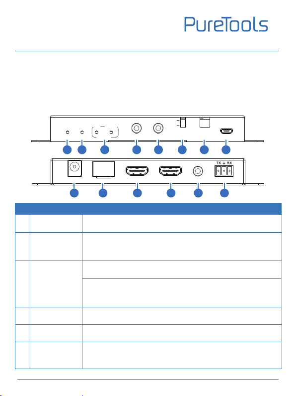
Transmitter
Input: 1 x HDMI IN [Type A 19-pin female]
1 x LINE IN [3.5mm Stereo Mini-jack]
1 x IR IN [3.5mm Stereo Mini-jack]
1 x RS-232 [3.81mm Phoenix connector]
1 x SERVICE [Micro USB, Update port]
Output: 1 x HDMI OUT [Type A 19-pin female]
1 x Optical Fiber Out [LC female]
1 x IR OUT [3.5mm Stereo Mini-jack]
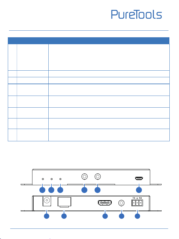
Receiver
Input: 1 x Optical Fiber In [LC female]
1 x IR IN [3.5mm Stereo Mini-jack]
1 x SERVICE [Micro USB, Update port]
Output: 1 x HDMI OUT [Type A 19-pin female]
1 x RS-232 [3.81mm Phoenix connector]
1 x IR OUT [3.5mm Stereo Mini-jack]
1 x AUDIO OUT [3.5mm Stereo Mini-jack]
Transmission
Distance Up to 10 km over single-mode fiber cable
IR Frequency 20KHz-60KHz
RS-232 Baud Rate 4800-115200bps