Purmo DSPRUMAP0D User manual

Badheizkörper WeldOn Sanierung
Towel Warmer Renovation
Grzejnik drabinkowy WeldOn A
Montageanleitung /
Assembly manual /
Instrukcja montazu
DSPRUMAP0D

2
Bauhöhe / Total height /
Wysokość
Nabenabstand / Center
distance / Rozstaw podłączeń [mm] [mm] [mm]
Baulänge / Total length /
Szerokość
Entlüftung / Ventilation /
Odpowietrznik
714 400, 500, 600,750, 900
5001134 400, 500, 600,750, 900
Vorlauf / Flow pipe /
Zasilanie
Rücklauf / Return pipe
Powrót
1764 400, 500, 600,750, 900
Andere Nabenabstände auf Anfrage / other connection distances on request
/Inne odległosci podłączeniowe na żądanie.
84 - 168
min.150
44 - 66
- 150
78 - 100
A
I
II
A
I
II
B
A
I
II
B
37
- 40
3
5
1
9
8
7
6
2
4
II B
*
Abb. 1
Fig. 1
Rys. 1
Abb. 2
Fig. 2
Rys. 2
Abb. 3 / Fig. 3 / Rys. 3
ACHTUNG!
IMPORTANT!
UWAGA!
Heizkörperrückansicht
Heating element rear view
Widok grzejnika z tyłu
Heizkörperabbildungen
DRysunki grzejników
PL
Radiator illustrations
GB

3
Installation / Montage des Badheizkörpers
D
Die Installation und Inbetriebnahme Ihres Badheizkörper ist von einer zuge-
lassenen Fachfirma durchzuführen. Bei der Installation sind die einschlägigen
Normen bzw. die nationalen elektrotechnischen Sicherheitsvorschriften, wie
ÖVE- und VDE Bestimmungen zu beachten.
Bei der Montage von Heizkörpern ist zu beachten, dass die Befestigung von
Heizkörpern so dimensioniert wird, dass sie für die bestimmungsgemäße
Verwendung und vorhersehbarer Fehlanwendung geeignet ist.
Hierbei sind insbesondere die Verbindung mit dem Baukörper sowie dessen
Beschaffenheit, die Geeignetheit des Montagezubehöres und die möglichen
Belastungen nach erfolgter Montage zu prüfen.
*Entsprechend der Europäischen Norm EN 60335-2-43+A1:2006-10-01:
WARNHINWEIS: Zur Vermeidung einer Gefährdung für sehr junge Kinder wird
empfohlen dieses Gerät so zu installieren, dass sich die unterste beheizte
Stange mindestens 600 mm über dem Fußboden befindet.
Unter Berücksichtigung der geometrischen Maße des Heizkörpers und der
Anschlusselemente (Armatur oder Ventile, Verschraubungen) ist die Ver-
rohrung vorzubereiten siehe (Abb. 1 bzw. Abb. 3).
Wir empfehlen, einen seitlichen Mindestabstand zum Heizkörper von 100 mm
einzuhalten. Dabei ist Nachfolgendes zu berücksichtigen:
Wird ein Elektroheizelement verwendet, kann dieses in eine der beiden 1/2“
Muffen Ieingedichtet werden (Abb. 3). Dabei sind die Hinweise der Montage-
anleitung für das Elektroheizelement zu beachten.
Die nicht verwendeten Anschlüsse mit den beigepackten Stopfen verschlie-
ßen, wobei in eine der beiden Muffen II die 1/2“ Entlüftung zu montieren ist.
Beim seitlichen Anschluss, der sich auf der rechten oder linken Seite des
Heizkörpers befinden kann, ist der Vorlauf oben und der Rücklauf unten
anzuschließen (Abb. 1).
WANDMONTAGE:
Anreißen, Bohren der Löcher A bzw. B - Bohrer Ø10 - und Setzen der Dübel
entsprechend dem Bohrbild (Abb. 1).
Befestigung der Wandfüße 5und waagrechtes Ausrichten derselben, wobei
die versenkten Langlochbohrungen 4nach unten stehen.
Dabei sollen die Wandmontageschrauben 6mit Beilagescheiben in der Mitte
der Langlöcher 9der Wandfüße montiert werden.
Lockeres Anziehen der Montagestutzen 2und Klemmteil 1zwischen den
horizontalen Rohren des Heizkörpers mit der Kreuzschlitzschraube 3.
Die am Heizkörper vormontierten Montagestutzen 2werden in die Wandfüße
5gesteckt und mittels Linsenkopfschraube 7locker miteinander verbunden.
Durch das versenkte Langloch im Wandfuß kann der Wandabstand variiert
und der Heizkörper vertikal ausgerichtet werden. Festziehen der Kreuzschlitz-
schraube 3und der Linsenkopfschraube 7, Abdeckkappen 8aufstecken.
Verstellmöglichkeiten der Wandfüße in Bauhöhenrichtung ist durch das
Langloch 9im Wandfuß gegeben, sollten die hydraulischen Anschlüsse nicht
genau passen.
Durch die vorhandenen Rohrleitungen des zu tauschenden Heizkörpers ist
der Wandabstand der Anschlüsse (Vorlauf und Rücklauf) vorgegeben.
Der Wandabstand kann mittels Montagestutzen 2an die vorhandenen Rohr-
leitungen, in der Bautiefe angepasst werden (Abb. 2).
Heizkörper hydraulisch anschließen.
Folgende Normen sind bei der Montage der Heizkörper
unbedingt einzuhalten:
- DIN 55900: Sprühbereich in Nassräumen
- VDI 2035: Vermeidung von Schäden in Warmwasserheizungsanlagen
- DIN 18017 Teil 3: Lüftung von Bädern und Toiletten ohne Fenster
- EN 14336: Heizungsanlagen in Gebäuden, Installationen und Abnahme
der Warmwasserheizungsanlagen
Die Badheizkörper sind geeignet für Warmwasserzentralheizungen mit einer
max. Betriebstemperatur von 110 °C und einem max. Betriebsüberdruck von
10 bar.
Der gleichbleibende hohe Qualitätsstandard unterliegt einer laufenden Eigen-
und Fremdüberwachung. Nacharbeiten am Heizkörper (z.B. Schweißarbeiten)
durch den Kunden sind nicht erlaubt.
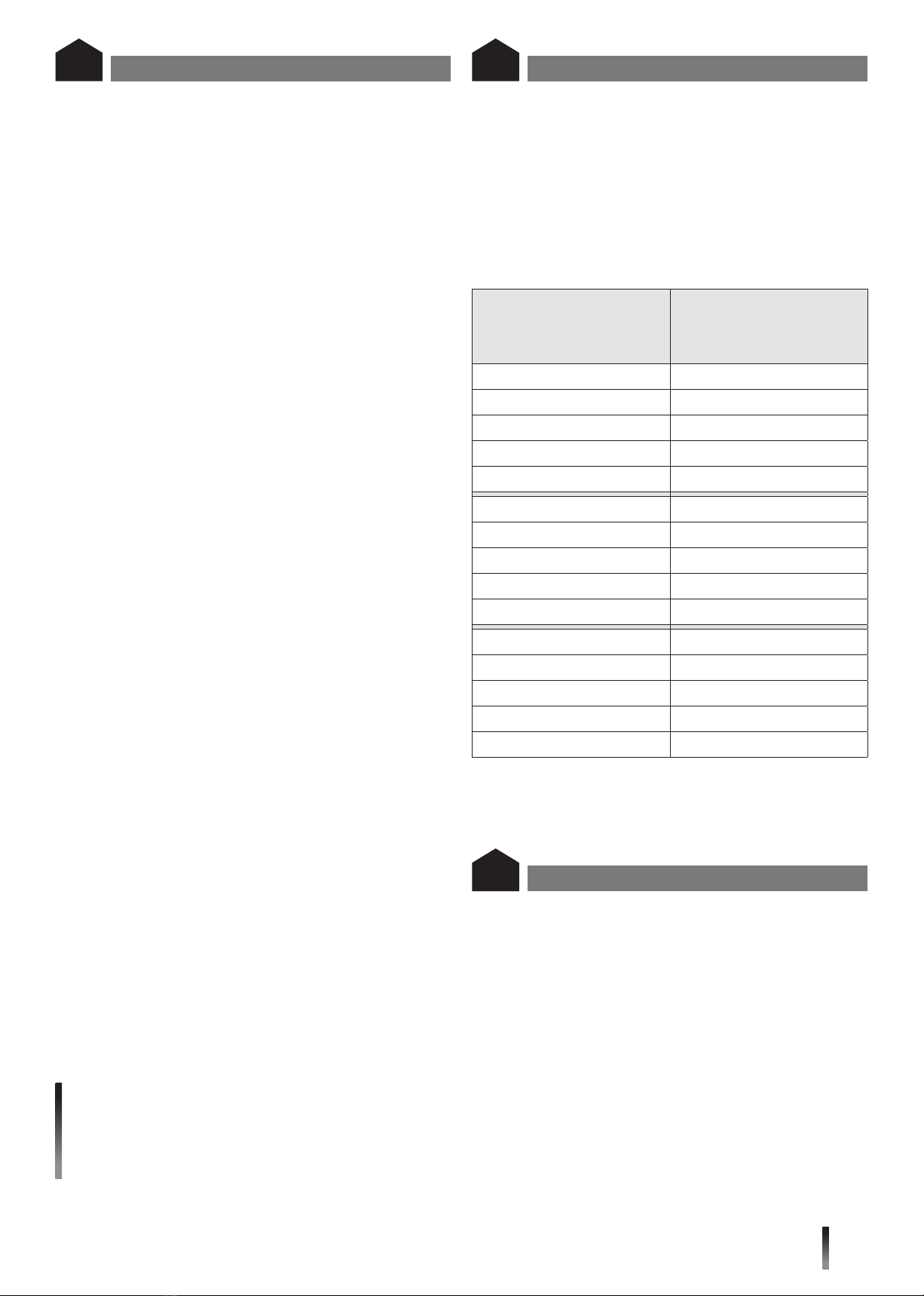
Die Badheizkörper können auch mit einer Elektrozusatzheizung ausgestattet
werden, wobei die nachfolgenden Empfehlungen einzuhalten sind:
Heizkörperdimension
Baulänge x Bauhöhe Elektroheizelement
Badheizkörper WeldOn Sanierung
[mm]
bei 60 °C
[W]
714 x 400 -
714 x 500 300
714 x 600 300
714 x 750 300
714 x 900 300
1134 x 400 300
1134 x 500 300
1134 x 600 300
1134 x 750 600
1134 x 900 600
1764 x 400 600
1764 x 500 600
1764 x 600 600
1764 x 750 900
1764 x 900 900
Das Wandmontagekonzept ist ein auf fertige Wände konzipiertes System.
Heizkörperbeschreibung
D
Die Badheizkörper sind hochwertige Produkte, die nicht nur der Raumheizung
dienen, sondern die auch zur Trocknung von Handtüchern geeignet sind.
Daher ist zu beachten, dass sie heiße Oberflächen besitzen. Es dürfen nur
Textilien, die mit Wasser gewaschen wurden, getrocknet werden.
Selbstverständlich ist es unzulässig, diesen Heizkörper als Kletter- oder
Sportgerät zu benutzen.
Zur Reinigung der Heizkörperoberflächen sind schonende, nicht scheuernde
Reinigungsmittel zu verwenden.
Für den Fall des Elektroheizungsbetriebes muss die Heizwasserausdehnung
immer bis zum Expansionsgefäß gewährleistet sein, z. B. durch Öffnen des
Rücklaufventiles. Um Wärmeverschleppungen in das Heizungsnetz zu ver-
meiden, wird in diesem Fall empfohlen, das Thermostatventil zu schließen.
Selbstverständlich darf die Elektroheizung nur in Betrieb genommen werden,
wenn der Heizkörper komplett mit Heizungswasser gefüllt ist.
Wird der Heizkörper elektrisch betrieben, darf er aus sicherheitstechnischen
Gründen nicht komplett abgedeckt werden.
Bedienung und Pflege
D

4
Radiator Sizes
Total length x Total height
Electrical
heating element
Towel Warmer Renovation
[mm]
at 60 °C
[W]
714 x 400 -
714 x 500 300
714 x 600 300
714 x 750 300
714 x 900 300
1134 x 400 300
1134 x 500 300
1134 x 600 300
1134 x 750 600
1134 x 900 600
1764 x 400 600
1764 x 500 600
1764 x 600 600
1764 x 750 900
1764 x 900 900
The bathroom radiators are high quality products which are suitable for drying
towels as well as heating rooms. For this reason it is important to remember
that they have hot surfaces. Only textiles that have been washed in water may
be dried.
Of course it is not permitted to use the radiators as climbing frames or sports
equipment.
The radiator surfaces must be cleaned with gentle non-scouring cleansing
agents.
For electrical heating operations the heating water must always be able to
expand to the expansion tank, e.g. by opening the non-return valve. To prevent
heat being transferred to the heating network in this case, we recommend
closing the thermostat valve. Of course, the electrical heating may only be
switched on after the radiator has been completely filled with water.
For safety reasons, the radiator must not be covered completely
if it is operated electrically.
Operation and care
GB
Installation / Assembly of bathroom radiators
GB Description of radiator
GB
IThe installation and startup of your bathroom radiators must be performed
by an authorized installation company. The applicable standards and national
electrotechnical safety regulations such as the ÖVE and VDE regulations must
be observed for installation..
For the correct installation of radiators it is essential that the fixing of the
radiator is carried out in such a way that it is suitable for intended use AND
predictable misuse.
A number of elements need to be taken into consideration including the fixing
method used to secure the radiator to the wall, the type and condition of the
wall itself, and any additional potential forces or weights, prior to finalising
installation.
*In accordance with European Standard EN60335-2-43+A1:2006-10-01:
WARNING: in order to avoid any danger to very young children, it is recom-
mended to install the appliance in such a way as to ensure that the lowest
heating bar is positioned at least 600 mm above the ground.
The piping must be prepared in consideration of the geometric dimensions of
the heating element and the connection elements (valves, screw connections)
– see (Fig. 1 and Fig. 3).
We recommend maintaining a space of at least 100 mm on the sides of the
heating element. Please also note the following:
If an electrical heater cartridge is used it may be sealed in one of the two 1/2“
sleeves I (Fig. 3). It is important that the instructions contained in the Electrical
heating assembly instructions are complied with.
Close the unused connections with the plugs supplied, whereby the 1/2“ air
bleed must be installed in one of the two tapping II.
At the side connection, which can be on the right or left side of the radiator, the
flow must be connected at the top and the return flow at the bottom (Fig. 1).
WALL INSTALLATION:
Marking, drilling of the holes Aand B– drill diameter 10 – and placement of
the pins according to the mounting dimensions (Fig. 1).
Fastening of the wall feet 5and horizontal alignment of these feet, whereby
the sunken oblong holes 4in the wall feet must face downward.
The wall mounting screws 6 must be mounted in the center of the oblong
holes 9of the wall feet with shims.
Loosely tighten the mounting connector 2and clamping piece 1between the
horizontal pipes of the heating element with the Phillips screw 3.
The mounting connectors 2already attached to the heating element are
inserted into the wall feet 5and connected together loosely with tallow-drop
screws 7.
The distance to the wall can be varied with the sunken oblong hole in the wall
foot and the heating element can be aligned vertically. Tighten the Phillips
screw 3and the tallow-drop screw 7, attach the end caps 8.
Oblong hole 9in the wall foot offers vertical adjustment options for the wall
feet in case the hydraulic connections do not fit exactly.
The wall distance of the connections (flow and return) is specified by the
existing pipes of the radiator to be replaced.
The wall clearance can be adjusted to the existing pipelines in the construction
depth by adjusting of the mounting studs 2(Abb. 2).
Hydraulically connect the heating element.
The following standards must be adhered to when installing radiators:
- DIN 55900: Spraying area in wet rooms
-
VDI 2035: Prevention of damage in water heating installations
- DIN 18017 Part 3: Ventilation of bathrooms and toilets without windows
- EN 14336: Heating systems in buildings. Installation and commissioning
of water based heating systems
The elegant bathroom radiators are suitable for central warm water heating
with a max. operating temperature of 110 °C and max. operating overpressure
of 10 bar.
The consistently high quality standard is subject to continuous internal and
third-party monitoring. Alterations to the heating element (e.g. welding work)
by the customer are not permitted.
The bathroom radiators can also be equipped with supplemental electrical
heating, whereby the following recommendations should be observed:
The wall installation concept is a system designed for finished walls.

5
Grzejniki dekoracyjne są produktami wysokiej jakości, służącymi nie tylko do
ogrzewania pomieszczeń, ale i do np. suszenia ręczników. Z tego też względu
nie należy zapominać, że posiadają one gorące powierzchnie.
Nie zezwala się natomiast na używanie grzejników do innych celów, jak np.
drabinki sportowe.
Do czyszczenia powierzchni grzejników należy stosować środki o łagodnym
działaniu, nie uszkadzających powierzchni.
W razie użycia grzałki elektrycznej, przyrost objętości wody musi być
skompensowany poprzez otwarcie zaworu powrotnego. Zaleca się także
zamknięcie głowicy termostatycznej na zasilaniu.
Ogrzewanie elektryczne może zostać uruchomione tylko wtedy, gdy grzejnik
wypełniony został całkowicie wodą.
Jeżeli grzejnik działa jako elektryczny poprzez użycie grzałki elektrycznej,
to ze względów technicznych oraz bezpieczeństwa nie może być całkowicie
zakryty.
Utilizare şi întreţinere
PL
Instalacja i montaż grzejników łazienkowych
PL Opis grzejnika
PL
Instalacja i uruchomienie grzejnika łazienkowego powinno zostać wykonane
przez uprawnioną do tego firmę. Należy również uwzględnić obowiązujące
normy i przepisy.
Uwaga: W celu zapewnienia prawidłowej instalacji grzejników ważne jest wyk-
onanie mocowania grzejnika w sposób, który jest zgodny z przeznaczeniem
grzejnika i w sposób zapobiegający jego nieprawidłowemu użytkowaniu.
Przed końcową instalacją należy wziąć pod uwagę między innymi metodę
mocowania grzejnika do ściany, rodzaj i stan ściany do której będzie
mocowany grzejnik oraz wszystkie potencjalne siły i obciążenia.
* Zgodnie z europejską normą EN 60335-2-43 + A1: 2006-10-01:
OSTRZEŻENIE: Aby uniknąć ryzyka dla bardzo małych dzieci, zalecamy
instalację tego urządzenia tak, aby najniższy pręt grzejny znajdował się co
najmniej 600 mm nad podłogą jest zlokalizowany.
Podłączenie instalacji należy przygotować uwzględniając wymiary grzejnika
oraz jego podłączenia (Rys. 1 lub Rys. 3). Zalecane jest utrzymanie
minimalnej 100mm odległości boku grzejnika do najbliższej ściany.
Zalecane jest utrzymanie minimalnej 100 mm odległości boku grzejnika do
najbliższej ściany.
Wskazówka: W przypadku instalowania grzałki elektrycznej zaleca się w tym
celu użycie jednej z muf I1/2”, a drugą z nich należy zaślepić korkiem
zaślepiającym, który jest dołączony do wyposażenia dodatkowego (Rys. 3).
Należy przy tym przestrzegać wskazówek, zalecanych przez danego produ-
centa grzałek, dotyczących samego montażu grzałki elektrycznej.
Nie używane podłączenia należy zamknąć zaślepkami, przy czym do jednej z
muf II należy wmontować odpowietrznik o średnicy 1/2”.
Przy podłączeniu bocznym, które może znajdować się po prawej lub lewej
stronie grzejnika, zasilanie musi być podłączone z boku u góry, a powrót z
boku na dole (Rys. 1).
MONTAŻ NA ŚCIANIE:
Zgodnie z podanymi na (Rys.1) wymiarami, wyznaczyć punkty na ścianie,
wywiercić otwory A - wiertło Ø10 i umieścić w nich kołki rozporowe (Rys. 1).
Zamocować stopki ścienne 5i ich poziome ustawienie, z wpuszczanymi
podłużnymi otworami 4skierowanymi w dół.
Śruby montażowe 6z podkładkami muszą znajdować się pośrodku otworów
podłużnych stopek ściennych 9.
Lekko dokręcić wsporniki montażowe 2i zaciski 1pomiędzy pionowymi rurami
grzejnika używając wkrętu z rowkiem krzyżowym 3.
Montaż naścienny grzejnika: zamontowane wstępnie na grzejniku wsporniki
montażowe 2wstawić w stopki ścienne 5i lekko połączyć ze sobą używając
wkrętu z łbem grzybkowym 7.
Poprzez wsunięty otwór podłużny w wsporniku ściennym można regulować
odstęp od ściany i wypoziomować grzejnik. Dokręcić wkręt z rowkiem
krzyżowym 3i wkręt z łbem grzybkowym 7. Wstawić nasadki ochronne 8.
W przypadku, gdy przyłącza nie pasują idealnie, istnieje możliwość regulacji
położenia stopek ściennych w pionie przy pomocy wsuniętych otworów
podłużnych 9znajdujących się w stopkach.
Odległość od ściany do osi przyłączy (zasilania i powrotu) określona jest
przez istniejące przewody c.o., które mogą być wymienione. Wtedy odległość
pomiędzy ścianą a osią podłączenia można wyregulować poprzez regulację
zawieszenia sciennego (Rys. 2).
Podłączyć grzejnik do instalacji grzewczej.
Poniższe normy są konieczne do zastosowania podczas
montażu grzejnika:
- DIN 55900: Strefy zroszone w pomieszczeniach wilgotnych
-
VDI 2035: Zapobieganie uszkodzeniom w wodnych instalacjach grzewczych
- DIN 18017 Teil 3: Wentylacja w łazienkach i toaletach bez okien
- EN 14336: Instalacje ogrzewcze budynków - Instalacja i przekazanie do
eksploatacji wodnego systemu grzewczego
Eleganckie grzejniki łazienkowe przeznaczone są do stosowania w wodnych
instalacjach centralnego ogrzewania o maksymalnej temperaturze roboczej
110°C i maksymalnym ciśnieniu roboczym 10 bar.
Wysoki standard jakości jest sprawdzany i utrzymywany dzięki ciągłemu
nadzorowi własnych i zewnętrznych służb kontrolnych.
Niedopuszczalne jest podgrzewanie grzejnika np. palnikiem lub użycie lu-
townicy, a także inne działania mogące powodować deformację grzejnika lub
zniszczenie powłoki lakierniczej.
Grzejniki łazienkowe mogą być również wyposażone w dodatkowy grzejnik
elektryczny, przy czym należy przestrzegać następujących zaleceń:
Idea montażu na ścianie pomyślana jest jako system przeznaczony dla
gotowych ścian.
Wymiary grzejnika
długość x wysokość
Moc grzałki
elektrycznej
WeldOn A
[mm]
przy 60
[W]
714 x 400 -
714 x 500 300
714 x 600 300
714 x 750 300
714 x 900 300
1134 x 400 300
1134 x 500 300
1134 x 600 300
1134 x 750 600
1134 x 900 600
1764 x 400 600
1764 x 500 600
1764 x 600 600
1764 x 750 900
1764 x 900 900

6
Notizen / Notes / Notatki

7
Notizen / Notes / Notatki

COMPANY ADDRESS:
PURMO GROUP LTD
Bulevardi 46
P.O. Box 115
FI-00121 Helsinki
www.purmogroup.com
Table of contents
Languages:
Other Purmo Bathroom Fixture manuals
Popular Bathroom Fixture manuals by other brands

Toto
Toto TTSH301C Installation and owner's manual

Hans Grohe
Hans Grohe Fixfit Square 26455000 Assembly instructions

Signature Hardware
Signature Hardware KEY WEST SHSH2030GMB Install

Project Source
Project Source FSI S4PC CROM manual

Gessi
Gessi Private Wellness 63211 manual

Graff
Graff TEP92 installation instructions