puroflux PF-63 Series User manual

OPERATION AND MAINTENANCE MANUAL
PAGE # 1
PF-63 Series Separator (ver. 7_10)
OPERATION AND MAINTENANCE MANUAL
PF-63 Series
Separator
PUROFLUX
FILTRATION AND CONTROL SYSTEMS
CORPORATION

PUROFLUX CORPORATION
PAGE # 2 PF-63 Series Separator (ver. 7_10)
PUROFLUX CORPORATION
PF-63 SERIES SEPARATOR
Please read this OPERATION AND MAINTENANCE MANUAL thoroughly and
understand all safety related issues before attempting any work on the PF-63
series separator.
INTRODUCTION
PUROFLUX is the right choice when it comes to having a more efficient, safe, and effective
system. With over 30 years of combined filtration experience, PUROFLUX engineers can find
a solution to a wide variety of filtration problems.
Following the guidelines listed in this manual will help to insure the safety of all personnel,
which maintain the separator unit and related equipment. If there are any questions on the
procedures or performance of the PF-63 series separator contact the local factory representative
or call the factory direct at (805)579-0216. Do not operate the separator until all questions
about operating procedures are answered by a qualified representative. This manual covers
recommended procedures for installation and anchoring, start-up and shut down, and safety
and maintenance.
NOTE:
All recommendations are minimums. The environment/operating conditions in which the
separator unit is installed will dictate the frequency of scheduled maintenance. Maintaining
your PF-63 Series Separator will assure a long trouble free life.
Puroflux Corporation
Phone (805)579.0216 • Fax (805)579.6005
Website: www.puroflux.com
E-Mail: [email protected]

OPERATION AND MAINTENANCE MANUAL
PAGE # 3
PF-63 Series Separator (ver. 7_10)
OPERATION AND MAINTENANCE MANUAL
CHAPTER 1
Receiving and Installation 4
Receiving Equipment 4
Design Criteria 5
Support and Lifting 5
Installation and Anchoring 6
Separator Requirements 7
System Piping Overview 8
Separator Unit Piping 8-9
Electrical Controls 10
Wiring Requirements 10
CHAPTER 2
Operation and Maintenance 11
Theory of Operation 11
General Maintenance 12
Pump Pre-Strainer 13
Pump and Motor 13
Cleaning and Adjusting Pump 14
Recovery System 14
Differential Indicator Option 14
Recovery Vessel Bag Change 15
CHAPTER 3
Start-Up Procedure 17-18
Operation In Cold Weather 18
Shutdown 19
Recommended Spare Parts 20
Fluid Treatment 20
Safety 20
Warranty 21
Pump Exploded View (Figure 2) 22
TABLE OF CONTENTS

PUROFLUX CORPORATION
PAGE # 4 PF-63 Series Separator (ver. 7_10)
Table I – Receiving / Inspection
SEPARATOR (PF-61 SERIES)
RECOVERY VESSEL (PFRV SERIES)
PRESSURE GAUGES
SCH 80 PVC INTERCONNECTING PIPING
ISOLATION VALVES (RECOVERY VESSEL)
MANUAL AIR VENT VALVE
MOTOR CONTROLS (NEMA 4X CABINET)
PUMP & MOTOR ASSEMBLY
PRE-STRAINER
DIFFERENTIAL PRESSURE INDICATOR
RECEIVING EQUIPMENT
Before accepting the separator equipment and prior
to signing the bill of lading, all equipment should be
checked thoroughly for any shipping damage. Make
sure that all required equipment noted on the bill of
lading is received. See Figure #1 and Table I for
components to be inspected upon receiving.
Check the model and serial number against the
invoice. Serial and model numbers can be found
on a nameplate located on the inside of the control
cabinet door.
PUROFLUX CORPORATION
CHAPTER 1
PF-63 Series Separator
Figure 1
Pressure Gauges
(TYP 2 PLC’S )
Outlet
SCH 80 PVC
Interconnecting Piping
Manual Air
Vent Valve
Pump and
Motor Assembly
Inlet
Coated
Steel Skid
NEMA 4X
Control Cabinet
(Automatic Units)
Recovery Vessel
Separator
Pre-strainer
RECEIVING AND INSTALLATION
Recommended procedures for the receiving of equipment and proper installation of the PF-63 series
separator.

OPERATION AND MAINTENANCE MANUAL
PAGE # 5
PF-63 Series Separator (ver. 7_10)
OPERATION AND MAINTENANCE MANUAL
SUPPORT AND LIFTING
The PF-63 series separators should be lifted only by the skid. If the unit is hoisted, lifting straps
must be placed around skid and should not come in contact with the separator package
components. The assembly must be fully supported from the bottom of the skid before lifting.
DESIGN CRITERIA
The PUROFLUX PF-63 series separator is designed for use in closed circuit or open process
liquid applications. Standard equipment design is 150 psi @ 100°F (temperature dependent -
higher design pressures and temperatures are available). The PF-63 series separator will
remove suspended solids with a specific gravity of 1.2 or higher down to 45 micron/325 mesh.
NOTE:
Never, install the PF-63 series separator in an application where the system pressure
exceeds the separator package design pressure.
The PF-63 series separator packages utilize a PF-61 series separator in conjunction with a
PFRV series recovery system. Standard units are equipped with inlet and outlet gauges, pump
and motor, cast iron pre-strainer, Sch. 80 PVC interconnecting piping, manual air vent valves,
coated steel skid, flow controller, isolation valves (recovery vessel), and differential pressure
indicator for the recovery system.

PUROFLUX CORPORATION
PAGE # 6 PF-63 Series Separator (ver. 7_10)
PUROFLUX CORPORATION
INSTALLATION AND ANCHORING
The PF-63 series separator is designed for use in both full flow and slip stream use on
pressurized closed systems or open atmospheric systems.
1. Determine the location and orientation of where the separator is to be installed in the piping
system or open sump. A three foot clearance is recommended around the separator for service.
2. Locate the separator as close to the system piping as possible.
Important Note:
Never install the PF-63 series separator in an application where the system pressure exceeds
the separator design pressure of the separator package.
3. Verify that the housekeeping pad will accommodate the weight of the separator under oper-
ating conditions. See Table II on page 7 for operating weights.
4. The PF-63 series separator should be rigidly anchored to the floor (see the specification
drawing for location and size of the anchor holes).
5. After the PF-63 series separator is installed in its permanent location, the inlet and outlet
gauges (if not previously installed) should be installed on the separator vessel (see figure #1
on page 4).
6. Before hook-up begins check the system's inlet (pump & pre-strainer), outlet and recovery
system for foreign objects, which may have entered during shipment.
7. Always use appropriate hardware to match the separator connections.
NOTE:
Mating flange bolts, gaskets and other miscellaneous fittings are not included with the separator.
8. The inlet connection of the separator is located on the side of the vessel and is pre-plumbed
from the pump discharge. The outlet is located at the top of the separator vessel. The purge
connection is located at the bottom of the vessel and is pre-plumbed to the inlet of the recovery
system. Flow to the separator must enter at the inlet connection and exit at the outlet connection.

OPERATION AND MAINTENANCE MANUAL
PAGE # 7
PF-63 Series Separator (ver. 7_10)
OPERATION AND MAINTENANCE MANUAL
SEPARATOR REQUIREMENTS
1. Puroflux separators are designed to operate within a specified range of 3 to 10 psi pressure drop
across the separator. It may be necessary to install a flow control or throttling valve downstream of
the separator in order to achieve the proper flow and pressure drop.
NOTE:
Operating outside the specified range of the separator can cause reduced efficiency and
possible damage to the separator or system.
2. The separator package should be installed to merge with the natural flow of the system,
never against it. A straight run of 5 to 6 pipe diameters up and down stream of the separator
is recommended to reduce turbulence.
3. The PF-63 series separators are equipped with a pump designed to maintain proper flows
through the separator system. Standard units are equipped with a pump to match the required
separator system flow (gpm) @ 60 feet of head (see Table V on page 13). Some installations
may require that a throttling valve be installed in the outlet line to regulate the flow or the pump
may need to be altered (lower/higher discharge head) to maintain proper flows.
4. The minimum inlet pressure should be at least equal to the pressure loss anticipated
through the PF-63 series separator plus the systems down stream pressure requirements.
5. The recovery system is pre-plumbed from the separator purge (waste) to the "INLET" of the
recovery system. The "OUTLET" of the recovery system is plumbed back to the suction side of
the pump (see figure #1 on page 4).
TABLE II - WEIGHT & VOLUME
MODEL PF-63 DRY (LBS.) OPER. (LBS.) VOL.(GALS.).)
PF-63-012 370 438 8
PF-63-015 372 440 8
PF-63-020 530 640 13
PF-63-025 640 752 14
PF-63-030 689 809 15
PF-63-040A 850 1067 26
PF-63-040B 970 1198 26
PF-63-050 1350 1822 36
PF-63-060A 1757 2197 53
PF-63-060B 1873 2317 53

PUROFLUX CORPORATION
PAGE # 8 PF-63 Series Separator (ver. 7_10)
PUROFLUX CORPORATION
SYSTEM PIPING OVERVIEW
1. Pipe sizes must be large enough to maintain proper flow. It is important to understand that
the selection of a separator is based on the flow rate through the separator (approx. 10 ft/sec.)
and not the separator pipe size (connections). If necessary reduce pipe runs at the separator
connections to maintain proper fluid velocity. Always follow good piping practices when running
piping. The separator connections may be smaller then the actual piping between the separator
and system. Upon request Puroflux can provide a typical installation drawing.
2. PVC, copper, steel or galvanized pipe are all acceptable, and may be used when installing
the separator. The choice of piping materials will depend on the design criteria and conditions
of each installation.
SEPARATOR UNIT PIPING:
Piping should be installed for PF-63 series separators on pressurized system or slip stream
applications as follows:
1.Table III on page 9 shows PF-63 series separator piping connections and sizes.
NOTE:
Do Not reduce the pipe sizes listed, the pipe sizes are minimums. If long runs, excessive
fittings or lifts are necessary, enlarge the pipe diameter in order to reduce friction loss.
2a. (Closed circuit or pressurized system) Run an influent line from the pressure side of the
system piping to the pump inlet connection labeled "INLET".
NOTE:
The influent line should be piped from the discharge side of the process system pump.
A service valve and flange/union should be installed in this line near the separator. For appli-
cation on pressurized systems where the system pump is utilized, the separator package
pump may not be required or should be sized to meet the dynamics of the system.
2b. (Open system or sump) Run an influent line from the deep or depressed portion of an open
sump to the pump inlet connection labeled "INLET".
NOTE:
If the separator package or the piping run is above the water level a check or foot valve
maybe required to maintain prime. A service valve and flange/union should be installed in
this line near the separator.

OPERATION AND MAINTENANCE MANUAL
PAGE # 9
PF-63 Series Separator (ver. 7_10)
OPERATION AND MAINTENANCE MANUAL
3a. (Closed circuit or pressurized system) Run an effluent line from the separator return
labeled "OUTLET" back to the system piping (low pressure side).
NOTE:
The effluent line should be piped to the suction side of the process system pump. A flow
control or throttling device is recommended in the effluent line (separator return) to regulate
flow through the separator. A service valve and flange/union should be installed in this line
near the separator.
3b. (Open system or sump) Run an effluent line from the separator return labeled "OUTLET"
back to the system sump on the opposing side of the suction (influent) line.
NOTE:
If the system dynamics dictate a lower or higher discharge pressure, the pump & motor may
require a change to match the actual system dynamics. A flow control or throttling device
could also be installed in the effluent line to regulate flow through the separator.
A service valve and flange/union should be installed in this line near the separator.
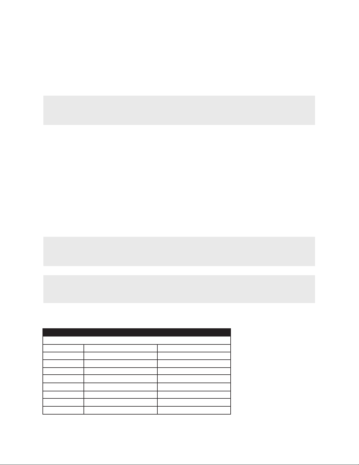
TABLE III - SIZE & CONNECTION
MODEL PF-63 INLET(INCHES) OUTLET (INCHES)
PF-63-012 2 (FLNG) 1-1/4 (MPT)
PF-63-015 2 (FLNG) 1-1/2 (MPT)
PF-63-020 3 (FLNG) 2 (MPT)
PF-63-025 3 (FLNG) 2-1/2 (MPT)
PF-63-030 3 (FLNG) 3 (FLNG)
PF-63-040A 4 (FLNG) 4 (FLNG)
PF-63-040B 4 (FLNG) 4 (FLNG)
PF-63-050 6 (FLNG) 5 (FLNG)
PF-63-060A 6 (FLNG) 6 (FLNG)
PF-63-060B 8 (FLNG) 6 (FLNG)
NOTE:
It is important that all piping and components associated with the filter system installation
must be supported to eliminate stress on the filter and piping.
Always follow local, county, state or other government agency requirements for piping
hook-ups.

PUROFLUX CORPORATION
PAGE # 10 PF-63 Series Separator (ver. 7_10)
OPERATION AND MAINTENANCE MANUAL
ELECTRICAL CONTROLS
Standard separator packages are equipped with a NEMA type 4X control cabinet containing a
door disconnect switch with thermal overload and short circuit protection.
IMPORTANT NOTE:
Standard voltage is 460v/3Ø/60 hz, 230v/3Ø/60 hz, 208v/3Ø/60 hz. All other voltages
are optional.
WIRING REQUIREMENTS
1. Install circuit breaker between the closest branch distribution panel and the control panel.
2. See table IV and V (on page 13) for amp draws and pump horsepowers. The control box is
pre-wired and includes a door disconnect switch with overload and short circuit protection.
Reference Figure #1 on page 4.
3. Hand-Off-Auto Switch (HOA) is supplied. The HOA switch is used to control the pump motor.
In the "Hand" mode the pump will start locally only. In the "Auto" mode the pump motor will be
started from a remote location.
NOTE:
The signal from the remote location is a dry contact. In the "Off" position the pump is off
however, there is voltage at the control panel.
NOTE:
Always follow local, county, state or other government authority's requirements for electrical
hook-up.
TABLE IV - HORSEPOWER / AMPERES
MOTOR HP MOTOR VOLTAGE AMPERAGE 3 PHASE
1 208 / 240 / 460 5 / 4 / 2
2 208 / 240 / 460 8 / 7 / 4
3 208 / 240 / 460 11 / 10 / 5
5 208 / 240 / 460 17 / 16 / 8
7 1/2 208 / 240 / 460 25 / 22 / 11
10 208 / 240 / 460 32 / 28 / 14
15 208 / 240 / 460 48 / 42 / 21
20 208 / 240 / 460 62 / 54 / 27
25 208 / 240 / 460 78 / 68 / 34

OPERATION AND MAINTENANCE MANUAL
PAGE # 11
PF-63 Series Separator (ver. 7_10)
PUROFLUX CORPORATION
OPERATION AND MAINTENANCE
Recommended procedures for, the proper operation and general maintenance of the PF-63
series separator.
Please read this entire OPERATION and MAINTENANCE MANUAL thoroughly and understand
all safety related issues before attempting any work on the PF-63 series separator.
THEORY OF OPERATION
The Puroflux PF-63 series separator utilizes high centrifugal forces to separate solids from liquids.
The suspended particulate is simply dropped from the carrying fluid where it is collected for discard.
The PF-63 separators do not require a backwashing and will not interrupt throughput when purging.
Because no backwash is required large amounts of system fluids will not be wasted. The
PF-61 series separator collects and concentrates particulate as it falls from the process fluid
into the accumulation chamber. Because the separator and the accumulation chamber are
at equal pressures, there is no need for any additional pressure to induce purging.
Influent is fed via the system pressure or external booster pump tangentially into the separator
acceptance chamber. The influent is spun in a downward motion pushing the suspended
particulate to the walls of the separator vessel by centrifugal forces. Suspended solids are
forced downward into the collection chamber for purge. The clean liquid then reverses direction
moving upward entering the vortex finder where it is then returned back to the process system.
Purging the accumulation chamber is done without excess waste of system fluid while the
separator package remains "on-line". The purge is set at a constant flow to the recovery system.
The purged waste is concentrated in the recovery system while the clean fluid is drawn back
into the system flow.
Chapter 2

PUROFLUX CORPORATION
PAGE # 12 PF-63 Series Separator (ver. 7_10)
OPERATION AND MAINTENANCE MANUAL
GENERAL MAINTENANCE PROCEDURES
Always follow the start-up and shut down procedures before and after any service or maintenance
is done on the separator unit. The PF-63 series separators are designed for low maintenance and
minimal service. With proper care the PF-63 series separators will give trouble free service. The
following is a list of maintenance check points and schedules.
1. Visually inspect separator package every 48 hours (min.) for proper operation. Check for
unusual noise or vibration.
2. Read pressure gauges (gauge reading should not exceed design pressure).
3. Clean pump pre-strainer (check as often as environment dictates).
4. Check the gasket condition each time the pre-strainer is serviced.
5. Check voltage and amperage draw on motor.
6. Read PFRV differential pressure indicator (indicator reading should not exceed 29 psid).
7. Replace or clean bag(s) @ 25 psid (recommended). Refer to Recovery Vessel Bag Change
section on page 15.
8. Inspect recovery system internal assembly each bag change.
9. Clean or replace bag(s) before blind-off occurs (check as often as environment dictates).
10. Lubricate the o-ring on retainer basket (applicable only to PFRV-3S and PFRV-3T) each
time the recovery system is serviced.
11. Lubricate the o-ring on the cover each time the recovery system is serviced.
WARNING:
Close and lock out all isolation valves to the separator package prior to performing
maintenance.

OPERATION AND MAINTENANCE MANUAL
PAGE # 13
PF-63 Series Separator (ver. 7_10)
PUROFLUX CORPORATION
PUMP PRE-STRAINER
The pump pre-strainer is mounted in front of the pump and is utilized to protect the pump from
large debris. The pre-strainer contains a corrosion resistant stainless steel basket with 1/8
inch mesh. The pre-strainer basket must be kept clean and free of debris.
NOTE:
Always relieve internal vessel pressure and follow the shut down procedure (on page 19)
before attempting any service work. Remove the pre-strainer lid bolts and remove the lid.
Remove the basket and clean all debris from inside the basket. Replace the basket and
lid, (check gasket alignment) and re-tighten the bolts. Make sure the gasket is in good
condition. A cracked or torn cover gasket can cause air leaks and poor performance.
Replace if necessary.
PUMP AND MOTOR
For standard units the pump wet end is cast iron bronze fitted. The close coupled pump and
motor assembly is bolted together with hex bolts for ease of maintenance or repair. The pump
utilizes a standard mechanical seal pressed into the motor bracket, which is bolted directly to
the pump volute. The pump shaft slides over the motor shaft and the pump impeller is keyed
on to the end of the motor shaft and locked in place with a hex jam nut or cap screw (See
Figure II on page 22).
The pump design conditions for the PF-63 series separators are the flow rates (GPM)@60 feet
of head (TDH) (See Table V). This correlates to approximately 26 psi discharge pressure at
design flow. Motor horsepowers are also listed.
WARNING:
Always disconnect and lock out all electrical power to the separator package prior to
performing pump maintenance.
TABLE V - MOTOR HORSEPOWERS
FLOW RATE @ 60 TDH
MODEL PF-63 MOTOR(HP) SYSTEM (GPM) PURGE (GPM)
PF-63-012 2 50 15
PF-63-015 3 80 15
PF-63-020 5 110 15
PF-63-025 5 160 15
PF-63-030 7.5 220 15
PF-63-040A 10 330 20
PF-63-040B 10 400 20
PF-63-050 15 600 20
PF-63-060A 20 900 20
PF-63-060B 25 1200 20

PUROFLUX CORPORATION
PAGE # 14 PF-63 Series Separator (ver. 7_10)
OPERATION AND MAINTENANCE MANUAL
CLEANING & ADJUSTING PUMP
Always follow the shut down procedure (on page 19) before attempting any repairs or adjust-
ments. The impeller should spin freely. If not, check for an obstruction or debris that may be
lodged between the impeller and volute or impeller and adapter bracket. If no debris can be
found and the impeller remains obstructed remove the bolts holding the volute to the motor
bracket and the two bolts holding the motor to the base (refer to Figure 2 on page 22). Slide the
motor and motor bracket away from the pump volute. Inspect the volute for foreign material.
Reverse the above procedures to reassemble (replace any gaskets which are not in good condi-
tion). Rotate the pump shaft manually after assembly to check clearance. Always follow the
start-up procedures (on page 17) whenever the separator unit has been turned off.
RECOVERY SYSTEM
The purged waste from the separator enters the inlet of recovery system and is distributed over
the bag(s) evenly. Suspended solids are trapped by the bag. The effluent (filtered) then passes
from the recovery system through the outlet and returned back to the separator system inlet. The
trapped particles cause the differential pressure across the bag(s) to rise. When the pressure
differential reaches a maximum of 25 psid the bag(s) will require a change out. The bag(s) can
be removed following the procedure outlined in the recovery vessel bag change section on
page 15.
OPTIONAL REMOTE DIFFERENTIAL
PRESSURE INDICATOR (DRY CONTACT)
The PFRV series recovery system can be supplied with an optional remote differential pressure
indicator (dry contact). The indicator is supplied in a NEMA 4X control cabinet, with dry contact
alarm and terminal blocks. It can be used with 12 or 24 volts. Do not hook-up any higher volt-
ages. Refer to wiring diagram provided with remote alarm controls.

OPERATION AND MAINTENANCE MANUAL
PAGE # 15
PF-63 Series Separator (ver. 7_10)
PUROFLUX CORPORATION
RECOVERY VESSEL BAG CHANGE
The most important step in changing filter bags is to make sure that the pressure is relieved
prior to opening the unit. This can be accomplished by the following steps.
1. Close the outlet isolation valve in the line leading from the recovery system outlet back to
the system pump suction.
2. Close the inlet isolation valve leading from the separator purge to recovery system inlet.
3. Open the manual air vent on the top of the recovery system to relieve any internal pressure.
4. If required, open the drain plug. The fluid drained from the recovery system may be returned
to the system.
5. Loosen the four bolts on the cover so that they are free and can be swung down. Rotate cover
by lifting up on the handle located on the vessel cover. Remove stainless steel bag retention
band by lifting straight up.
6. Remove dirty filter bag. Lift the bag straight up by the lifting strap.
7. Inspect the retaining basket and o-ring. Remove and clean if necessary. Replace retaining
basket o-ring if needed.
8. If the bag is not worn or in need of replacement, it can be washed. To wash the bag, turn it
inside out and flush with a hose. Replace the bag if the differential pressure does not return to
the clean start-up differential pressure. Replace by inserting the clean filter bag into the retaining
basket (already installed) and form the bag to the contours of the basket by pressing against the
retaining basket. The bag support ring must be seated flush on retaining basket.
NOTE:
A bag change can be done while the separator remains in service. However, it is recom-
mended that the separator package be shut down while performing a bag change.
NOTE:
If the bag is completely blinded off, the bag may not drain and may be heavy.
NOTE:
For the PFRV-3S & 3T series (3 bag unit) the bag hold down ring is secured in place by a
3/8" nut and washer located in the center of the retaining basket plate. To remove the hold
down ring, remove the nut and washer then lift the ring vertically.
For the PFRV-3S & 3T series raise the cover by turning the handles on the davit clockwise
until the cover is clear of the recovery system housing. Swing to either side.

PUROFLUX CORPORATION
PAGE # 16 PF-63 Series Separator (ver. 7_10)
OPERATION AND MAINTENANCE MANUAL
9. Once bag is inserted into the retaining basket insert stainless steel bag retention band back
into place.
NOTE:
For installation of the bag/basket hold down ring on PFRV-3S & 3T series (3 bag unit), place
it over the retaining plate stud located in the center of the retaining basket plate. Secure the
hold down ring with the 3/8" nut and washer. Do not over tighten the hold down nut.
10. Inspect the cover and o-ring for foreign matter, and clean all surfaces. Check positioning of
the o-ring, which should be properly seated in the recovery system cover.
11. Close cover carefully. Do not drop.
WARNING:
The cover is heavy, be careful not to pinch hands and/or fingers.
12. Re-tighten cover bolts evenly and securely.
NOTE:
Always follow the start-up procedures (see page 17) whenever the recovery system has
been turned off.

OPERATION AND MAINTENANCE MANUAL
PAGE # 17
PF-63 Series Separator (ver. 7_10)
OPERATION AND MAINTENANCE MANUAL
CHAPTER 3
START-UP PROCEDURE
Before initial start-up or after a shutdown period, the filter unit should be thoroughly inspected.
Important Note:
Perform the first two procedures with the electric power off and locked out. Refer to the Fluid
Treatment section on page 20 regarding the safeguarding of maintenance personnel from
biological contaminants prior to start-up.
1. Check the pump pre-strainer by removing the lid, inspect the cover gasket for wear. Replace
cover gasket if necessary. Clean debris from the pre-strainer basket. Prime the pump if neces-
sary and replace the basket, lid and fasteners.
NOTE:
All electrical power to the separator package must be locked out.
2.Turn the pump and motor shaft by hand to ensure free rotation.
NOTE:
All electrical power to the separator package must be locked out.
3. Check the recovery system by loosening the four bolts holding the cover. Inspect the cover
o-ring for cracks or wear, replace it if necessary. Refer to Bag Change section on page 15.
4. Clean any debris from the bag(s) or support basket. Inspect the bag(s) for wear or debris.
Change if necessary.
5. Inspect the basket o-ring (applicable only to PFRV-3S and PFRV-3T) and retaining basket
and bag(s) for proper installation.
6. Lubricate o-rings.
7. Verify that the recovery system cover is properly positioned and locked down secure.
8. Verify that the service valves in the inlet and outlet line are open. Bump the motor and check
the arrow on the pump volute for proper rotation. Turn the pump motor off. Do not run the
pump for an extended period of time rotating backwards. Have a qualified electrician change
leads to correct rotation.
9. Open the manual air relief valves on top of the separator and recovery system. Open the
inlet isolation valve to the recovery system only.
NOTE:
The outlet isolation valve on the recovery system should remain closed.

PUROFLUX CORPORATION
PAGE # 18 PF-63 Series Separator (ver. 7_10)
OPERATION IN COLD WEATHER
When the PF-63 series separator is exposed to below-freezing temperatures, it will require
protection to prevent freezing. An indoor installation in a heated room is the best way to preventing
freezing of any liquid in the separator package. If an indoor installation is not practical, sufficient
insulation or supplemental heat must be supplied. Heat tape and insulation around the liquid
filled components must be used to prevent freezing. The separator package should be drained
when not in use for long periods of time. See shutdown section on page 19.
PUROFLUX CORPORATION
10. Start the pump and fill the separator and recovery system. Once a steady stream of water
is coming out and all air has been evacuated the manual air relief valves can be closed. Now
slowly open the outlet valve on the recovery system.
11. Check the voltage and current of all leads on the pump motor. The correct amperage draw
can be found on the motor nameplate or in Table IV on page 10.
12. Check the separator package for any unusual noise or vibration. Shut separator unit off
and contact your local PUROFLUX representative if there are any questions about the
operation or performance of the separator unit.
13. Check the separator package and all integral piping to the unit for any air or fluid leaks.
All air leaks must be found and repaired. Failure to do so could result in poor performance or
personal injury.
14. Check the gauges and pressure differential indicator and record the clean start up
differential pressures. Use the starting pressure as a bench mark whenever routine
maintenance is preformed.
15. After several hours of run time from start up perform steps 11 through 14 again.

OPERATION AND MAINTENANCE MANUAL
PAGE # 19
PF-63 Series Separator (ver. 7_10)
SHUTDOWN
The following service should be performed if the separator package is off line for a
prolonged time period.
1. Shut off and lock out all electrical power.
2. Close the service valves in the inlet and outlet lines to and from the separator package.
3. Relieve all pressure from the separator package and piping. Open the manual air relief
valves located on top of the separator and recovery vessel and leave the valves open.
4. Drain all external piping to and from the separator package.
5. Open the drain plugs on the pump pre-strainer housing and the pump volute. Allow all the
liquid to drain and then replace the drain plugs.
6. Open the purge valve and allow the separator vessel to drain fully (will drain to recovery
vessel).
7. Remove the drain plug located at the bottom of the recovery vessel. Allow the liquid to drain
and then replace the drain plug.
8. Remove the bolts from the pump pre-strainer cover. Remove the cover and clean debris
from the pump pre-strainer basket. Inspect the gasket and lubricate (replace gasket if
necessary). Replace the pre-strainer basket, gasket and cover and then tighten bolts.
9. Loosen the four bolts on the recovery vessel cover so that they are free and can be swung
down. Rotate cover by lifting up on the handle located on the vessel cover.
10. Remove stainless steel bag retention band. Clean or change the recovery vessel bag.
Refer to recovery vessel bag change section on page 15.
11. Reposition bag and stainless steel bag retention band back into recovery vessel.
12. Inspect recovery vessel cover o-ring and lubricate (replace o-ring if necessary).
13. Reposition recovery vessel cover and re-tighten bolts evenly and securely.
14. Close the manual air relief valves located on the top of the separator and recovery vessel.

PUROFLUX CORPORATION
PAGE # 20 PF-63 Series Separator (ver. 7_10)
RECOMMENDED SPARE PARTS
PUROFLUX maintains a complete stock of replacement parts. When ordering replacement or
stock parts, be sure to include the unit serial and model numbers.
The following spare parts are recommended:
1. Inlet/outlet gauges
2. Pump pre-strainer cover gasket
3. Pump seal and gasket kit
4. O-ring for recovery system cover
5. O-ring for retainer basket (applicable only to PFRV-3S and PFRV-3T)
6. Replacement bags
FLUID TREATMENT
Separation is an effective way of reducing the level of suspended solids in a system. However,
it is only one portion of a complete treatment program. Dissolved solids will not be removed from
the system by separation. It is important to realize that the dissolved solids will concentrate, and
can cause damage to a system. Furthermore airborne impurities and biological contaminants
may be introduced into the system.
To control all potential contaminants, a treatment program must be employed by a competent
professional. Such treatment should be initiated before the system start-up and continued regu-
larly thereafter.
OPERATION AND MAINTENANCE MANUAL
SAFETY
All electrical, mechanical, and rotating machinery are potential hazards. It is important to be
familiar with the design, construction, and operation of all equipment before performing any
work. Always use adequate safeguards (including use of protective clothing where necessary or
required) whenever installing, operating or working on the equipment.
Care should be taken when working on, near, or around this equipment. Appropriate safeguards
must be established to prevent the personnel and/or public from injury and to prevent damage
to the equipment, affiliated system and premises.
It is important to be thoroughly familiar with the equipment, associated system, controls, and the
procedures set forth in this manual. Only qualified personnel should operate, maintain,
and repair this equipment. Always follow proper procedures and use the correct tools, when
handling, lifting, installing, operating, maintaining, or repairing the equipment. This will aid in the
prevention of personal injury and/or property damage.
This manual suits for next models
10
Table of contents
Other puroflux Water Filtration System manuals
Popular Water Filtration System manuals by other brands

Winterhalter
Winterhalter RoMatik XS operating instructions

BWT
BWT Infinity A Installation and operating manual

McNeilus
McNeilus STREET SMART MFS quick start guide

Philips
Philips Micro Pure WP3811 user manual

OMEGA AIR
OMEGA AIR TDM16M Installation and operating manual

Water quality
Water quality VIQUA VH150 owner's manual

Klimawent
Klimawent WET-5000 Use and maintenance manual

GE
GE 000 gpd Operation and maintenance manual

Waterwise
Waterwise Showerwise Deluxe installation instructions

SuperFish
SuperFish TopClear 5000 user manual

SpectraPure
SpectraPure MC-RODI-200UHE Owner's Manual & Installation Instructions

wpro
wpro 480181700592 installation and replacement