PURSUIT PRO-9800 User manual

128-6528
1 of 28
Model PRO-9800
Installation Manual
RY
SELECTABLEFEATURES
Note : The method of manual override can either be selected to operate from the valet switch or operate as custom code. Be
certain to place a check mark indicating the method used in the box located on the last page of the owner's manual.
RF Programmable Features :
Feature Selection 1 Chirp 2 Chirps 3 Chirps 4 Chirps Default
1st DoorL/UL 1 Sec. 3.5 Sec. 1 Sec L, Dbl. U/L 1 Sec.
2nd Accy Lock Auto Lock On Auto Lock Off Auto Lock Off
3rd Accy. UL Auto UL Dr. Auto UL All Auto UL Off Auto UL Off
4th Headlights On Arm OnDisarm On Both Off Both
5th Passive Locks Passive Active Active
6th Passive/Active Arm Passive Arm Active Arm Active Arm
7th Black/Blue (Aux O/P) SinglePulse As Feature #1 Single
8th Siren/Horn Siren/Horn Siren Only Horn Only Siren/Horn
9th Horn Chirp 10mS 16mS 30mS 16mS
10th Override Method CustomCode Valet Valet
11th Two Step Unlock On Off Off
12th Chirp Delete From Tx On Off Off
To program these selectable features;
Action System Response
Turn ignition on No response
Press and release the valet switch 3 times 1 Chirp - LED 1 flash
Within 3 seconds, turn ignition Off Short chirp, then long chirp
First Then turn the ignition back On 1 chirp = 1 second door locks
Press transmitter Lock button to change 2 chirps = 3.5 second door locks
Press transmitter Lock button to change 3 chirps = 1 sec. lock, dbl 1 sec. unlock
or
Second Press and release the valet switch 2 chirps = auto locks off
Press transmitter Lock button to change 1 chirp = auto locks on
or
Third Press and release the valet switch 3 chirps = auto unlock off
Press transmitter Lock button to change 1 chirp = auto unlock drivers door only
Press transmitter Lock button to change 2 chirps = auto unlock all doors
or
Fourth Press and release the valet switch 3 chirps = headlight output when arming and disarming
Press transmitter Lock button to change 4 chirps = headlight output off
Press transmitter Lock button to change 1 chirp = headlight output when arming
Press transmitter Lock button to change 2 chirps = headlight output when disarming
or
Fifth Press and release the valet switch 2 chirps = active locks
Press transmitter Lock button to change 1 chirp = passive locks
or
Sixth Press and release the valet switch 2 chirps = active arming
Press transmitter Lock button to change 1 chirp = passive arming
or
Seventh Press and release the valet switch 2 chirps = as feature #1
Press transmitter Lock button to change 1 chirp = single pulse

128-6528
2 of 28
THIS PAGE INTENTIONALLY LEFT BLANK
2

128-6528
3 of 28
or
Eighth Press and release the valet switch 1 chirp = siren and horn output
Press transmitter Lock button to change 2 chirps = siren output only
Press transmitter lock button to change 3 chirps = horn output only
or
Ninth Press and release the valet switch 2 chirps = horn chirp output 16mS
Press transmitter Lock button to change 3 chirps = horn chirp output 30mS
Press transmitter Lock button to change 1 chirp = horn chirp output 10 mS
or
Tenth Press and release the valet switch 2 chirps = valet switch override operation
Press transmitter Lock button to change 1 chirp = custom code override operation
or
Eleventh Press and release the valet switch 2 chirps = 2 step unlock off
Press transmitter Lock button to change 1 chirp = 2 step unlock on
or
Twelfth Press and release the valet switch 2 chirps = chirp delete from transmitter inactive
Press transmitter Lock button to change 1 chirp = chirp delete from transmitter active
Press and release the valet switch Exit program mode
or
Turn ignition key off Exit program mode
Note : Once you enter the feature programming mode, do not allow more than 15 seconds to pass between steps or the
programming will be terminated.
This Remote Start/Alarm System is designed to be used with Automatic Transmission- Fuel Injection
Vehicles Only! The unit provides a selectable ignition control that allows a number of selectable timed outputs
for glow plug pre-heat in addition to a "Wait To Start Input" either of which may be required for certain diesel
vehicles, (see selectable feature #9 & or Green/Yellow Wire). If the diesel engine has a instant fire, (no glow
plugpre-heat system), feature #9 should remain in the default Gasoline mode setting. For dieselapplica-
tions,consultyourdealerforthetype of ignition system used in your particular vehicle. Regardless of the
vehicle, Gasoline or Diesel, for every installation, the vehicle MUST HAVE a Tach Signal Input, Auto-
matic Transmission and Fuel Injection.
INSTALLATION OF THE MAJOR COMPONENTS:
CONTROLMODULE:
Selectamountinglocationinsidethepassenger compartment (up behind the dashboard). The mounting
location selected must be within 24" of the ignition switch wiring harness to allow connection of the 6 pin
mainwiringharness.
Becertain thatthe chosenlocationwill notinterfere withproperoperationofthe vehicle. Avoidmountingthe
moduleto or routingthewiring around thesteeringshaft/column, as themoduleor wiring maywraparound
or block the steering wheel preventing proper control of the vehicle. Secure the module in the chosen
location using cable ties or screws as necessary.
Do Not Mount The Module In The Engine Compartment, as it is not waterproof.
SIREN:
Select a location in the engine compartment that is not accessible from below the vehicle. The selected
location must be clear of hot or moving parts within the engine compartment The siren must be pointed
downwardtopreventwaterretentionandtheflaredendmustbepointedawayfromandoutoftheengine
compartment for maximum sound distribution. Before securing the siren, check behind your chosen
location to assure that the mounting screws will not penetrate any factory wiring or fluid lines. Secure the
siren mounting bracket using #8 self taping screws or by first using the mounting bracket as a template,
scribeormarkthemounting holes. Drill the marked holes using a 1/8" drill bit, then mount the siren using
#8 sheet metal screws.
HOODAND TRUNK PINSWITCHES:
The pin switches included in this package are intended for protecting the hood and trunk areas of the
vehicle. In all cases, the switch must be mounted to a grounded metal surface. When the pin switch is
3

128-6528
4 of 28
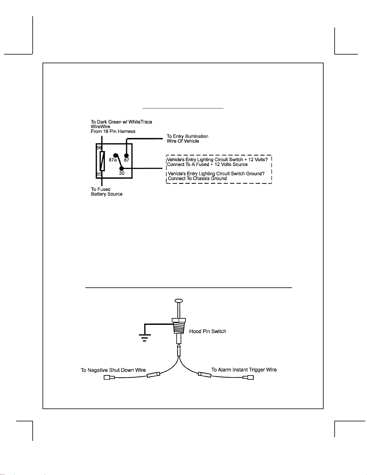
activated,(hood/trunkopen), itwill supply a ground to the input wire activating the alarm. In addition,the
hoodswitchisrequired for the safety shut down oftheremotestartunit. Ifthe vehicle is being worked on,
this hood switch prevents the remote start activation even if the RF command to start is issued. This
switch must be installed in all applications. Failure to do so may result in personal injury or
property damage. Mount the switches in the hood and trunk locations away from water drain paths. If
necessary, the included brackets may be used to move the switch away from rain gutters or allow
mounting to the firewall behind the hood seal. In both cases the switch must be set up to allow the hood
or trunk door to depress the switch at least 1/4 inch when the hood or trunk is closed and fully extended
when the hood or trunk is opened. For direct mounting, a 1/4 inch hole must be drilled. Carefully check
behindthe chosen locationtoinsure the drillwillnot penetrateanyexistingfactory wiringorfluid lines. Drill
a 1/4" hole in the desired location and thread the pin switch into it using a 7/16" nut driver or deep well
socket. If using the mounting bracket, first secure the bracket to the desired location and secure the pin
switchinthepre-threaded mounting bracket hole.
DASHMOUNTEDLED:
Thesmall LEDincluded in thekit willserveas a visual indicatorofthe alarm's status and provideavisual
deterrentto a potentialthief.The LED alsoprovidesimportant feed backinformationduring the transmitter
andfeature programmodes.The LEDshouldbe installedinthe dashinan areahighlyvisible sothatit may
be seen from the driver's seat as well as from outside the vehicle. Inspect behind the chosen location to
insure that the drill will not penetrate any existing factory wiring or fluid lines. Carefully drill a 1/4" hole in
the desired location and pass the connector end of the LED through the hole and toward the control
module. Press the LED firmly into place until it is fully seated in the mounting hole.
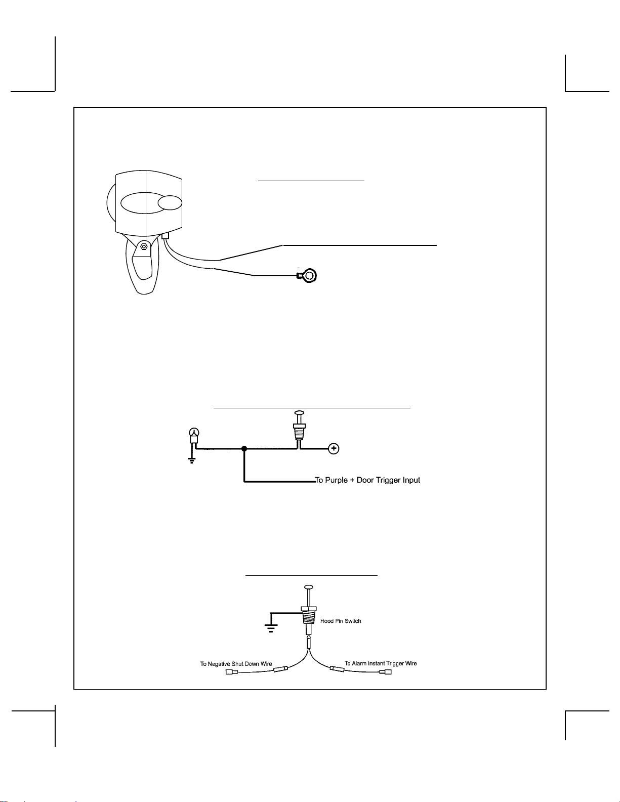
THERECEIVER/ANTENNAASSEMBLY:
The Superheterodyne Receiver Antenna Assembly provided with this unit allows routing from below the
dashboard formaximumoperatingrange. Choosea locationabovethe beltline (dashboard)ofthe vehicle
for best reception. Special considerations must be made for windshield glass as some newer vehicles
utilize a metallic shielded window glass that will inhibit or restrict RF reception. In these vehicles, route
theantennatowardarearwindowlocationforbestreception. Securetheantennawithdoublesticktape
provided. Aftersecuringthe antenna with tape, we advise alsosecuringasectionof the antenna cable to
afixed support. This willpreventthe antennafromdroppingdown incasethe double sticktapeis exposed
to extreme heat which may loosen it's gummed surface. Route the connector toward the control module
using caution not to pinch the cable as this will cause poor or no RF reception to the control module.
VALET/PROGRAM/MANUALOVERRIDE SWITCH:
Select a mounting location that is easily accessible to the operator of the vehicle. It is not necessary to
conceal the switch. However, concealment is recommended as it offers a higher level of security. The
switchcanbe mounted to the lower dash panelinthedriver'sarea. Inspect behind the chosen location to
insurethat adequateclearanceis allowedforthe bodyofthe switch, andalso that thedrillwill notpenetrate
any existing factory wiring or fluid lines. Drill a 9/32" hole in the desired location and mount the switch by
passingitthroughthepanel from the underside. Secure the switch using the nut, star washer. Route the
switch'sconnectortowardthecontrolmodule.
NOTE: During the program sequence, there are times when this switch and the ignition switch will be used
simultaneously. We recommend that the push-button switch be mounted on the left side of the ignition
switch to facilitate this operation.
CONTROLSWITCH:
Selectamountinglocationknownandaccessible to the operator of the vehicle. A lower dash panel, kick
panel, or glove box is desirable. Inspect behind the chosen location to insure that adequate clearance is
allowedfor thebodyofthe switch,andalso thatthedrill will notpenetrateany existingfactorywiring or fluid
lines. Drilla 1/4" holeinthedesired location andmountthe switch bypassingitthrough the panelfromthe
underside. Secure the switch using the nut, star washer, and on/off face plate. It is suggested that the
switchbe orientedtoallowtheon positiontobe uptoward thedriverand theoffpositiontobe downoraway
fromthedriver. Route the switch's connector toward the control module.
4

128-6528
5 of 28
SHOCKSENSOR:
Select a centrally located, solid mounting surface for the shock sensor that will allow consistent opera-
tionfromallareasof the vehicle. The selected location must be within 18" of the control moduletoallow
routing and connecting of the 4 pin harness. Secure the shock sensor to the chosen location using two
#8 self tapping sheet metal screws. The sensor can also be secured to an existing dash brace using
cable tie straps. Whichever mounting method is used be sure to allow access to the sensitivity adjust-
ment potentiometer for use later in the installation.
STARTER INHIBIT RELAY:
Select a mounting location within 12" of the ignition switch's low current start solenoid wire. Secure the
relay to an existing harness in the chosen location using a cable tie around the relay's wiring harness.
CAUTION! Donotwire tiethemetal bracket toanexisting wiringharnessas vibrationmaycause chaffing
and shorting damaging the factory wiring. If an existing harness is not available then secure the relay's
metalmounting tab toanunder dash metalbracewith a #8selftapping sheet metalscrew. Wirethe relay
as per the diagram found later in this manual.
Thisunitis to be used in vehicleswithAUTOMATIC TRANSMISSIONS only! Althoughthis combination
Alarm/Remote Start unit is a sophisticated system with many advanced features, IT MUST NOT be
installed into a vehicle with a manually operated transmission. Doing so may result in serious per-
sonalinjuryand property damage.
IMPORTANT!
DONOTPLUGTHESIXPINMAINPOWERHARNESSORTHEMULTIPININPUT/OUTPUTHARNESS
INTO THE CONTROL MODULE UNTIL ALL CONNECTIONS TO THE VEHICLE HAVE BEEN MADE.
AFTER SELECTING YOUR TARGET WIRES AS DEFINED BELOW, DISCONNECT THE NEGATIVE
BATTERYCABLEFROMTHE VEHICLEBATTERYPRIORTO MAKINGANYCONNECTIONS.
WIRING THE 6 PIN MAIN POWER HARNESS:
RED w/ WHITE Trace Wire: + 12 volts Battery 1 Source
Connect this wire to a + 12 VDC constant source found at the vehicle's ignition switch using the 30 Amp
fuse and holder provided. This wire provides power for the control circuit as well as the ignition 1 and
ignition 2 relays.
RED Wire: + 12 Volts Battery 2 Source
Connect this wire to a + 12 VDC constant source found at the vehicle's ignition switch using the 30 Amp
fuseand holder provided, butNOTthesame vehicle wireasused by thebattery1source. Most vehicles
havemorethanonebatterysource supplying power to the ignition switch. Separate feed wires must be
usedfor the RedandRed/Whitewires. If your vehicledoesnot have twobatteryfeed wires attheignition
switch then it is possible to connect both wires to the vehicle's battery. This wire provides power for the
start relay and the accessory relay.
IMPORTANT!
It is the responsibility of the installing technician to determine the load factor of the vehicles electrical
circuitswhen the vehicleisrunning, and toadequatelyfuse thetwopower wires basedonthat load. If the
vehicle, running under load with the air conditioner, heater blower motor, and accessories exceed 24
Amps continuous, we recommend that two fuses be used in combination on each power wire as shown
below. ForadditionalinformationseeTechUpdate issued 9/30/96.
5

128-6528
6 of 28
YELLOW Wire: Starter Output
Careful consideration for the connection of this wire must be made to prevent the vehicle from
starting while in gear. Understanding the difference between a mechanical and an electrical
Neutral Start Switch will allow you to properly identify the circuit and select the correct installa-
tion method. In addition you will realize why the connection of the safety wire is required for
all mechanical switch configurations.
Failureto make this connection properly can result inpersonal injury and property damage.
Inallinstallationsit is the responsibility of the installing technician totesttheremotestartunit and ensure
that the vehicle cannot start via RF control in any gear selection other than park or neutral.
Inbothmechanical and electricalneutralstartswitch configurations, the connectionof theYellowwirewill
bemadetothelow current start solenoid wire of the ignition switch harness. This wire will have+12volts
when the ignition switch is turned to the start (crank) position only. This wire will have 0 volts in all other
ignition switch positions.
NOTE: This wire must be connected to the vehicle side of the starter cut relay (when used). For the
electrical neutral switch configuration, this connection must be made between the starter inhibit relay,
( when used ) and the neutral safety switch as shown in the following diagram.
Failure to connect this wire to the ignition switch side of the of the neutral safety switch can result in
personalinjury and propertydamage.
SEENEUTRAL STARTSAFETYTESTFOR FURTHERDETAILS.
YELLOWSTART WIRE DETAIL
BLUE Wire: Ignition 1 Output
Connect this wire to the ignition 1 wire from the ignition switch. This wire will show +12 volts when the
ignition key is turned to the "ON" or "RUN" and the "START" or CRANK" positions, and will have 0 volts
when the key is turned to the "OFF" and "ACCESSORY" positions.
ForDieselApplications, this wiremustbeconnected to the ignitioncircuitthat powers the glowplugsifthe
vehiclerequires glow plugpre-heating.(See selectable feature#9)
GREEN Wire: Ignition2 Output
Connect this wire to the ignition 2 wire from the ignition switch. This wire will show + 12 volts when the
ignition key is turned to the "ON" or "RUN" position and is some cases the "START" or CRANK" position.
This wire will show 0 volts when the key is turned to the "OFF" and "ACCESSORY" positions.
NOTE:Seeprogramming information concerning this wire toallowoutputduring the "START"mode.
VIOLET Wire: Accessory Output
Connect this wire to the Accessory wire from the ignition switch. This wire will show + 12 volts when the
ignition switch is turned to the "ACCESSORY" or "ON" and "RUN" positions, and will show 0 volts when
the key is turned to the "OFF" and "START" or "CRANK" positions.
6

128-6528
7 of 28
WIRING CONNECTIONS: Multi Pin Accessory Input/Output Harness
White w/ Red Trace Wire: Parking Light Flasher Feed
Thiswireis the common contact of theonboardparkinglight flasher relay. If the vehicle you areworking
on has +12 volt switched parking lights, connect this wire to a fused + 12 volt source. (Max. 15 Amps)
NOTE: Ifthevehicle'sparkinglightsaregroundswitched,connectthiswire to chassis ground.
White Wire: Parking Light Flasher Output
Thiswireis the normally open contact of the onboardparkinglightflasher relay. Connect this wire tothe
vehicle parking light feed wire. See diagram below for details on wiring positive switched parking light
circuits. Parking Light Wiring Detail
7

128-6528
8 of 28
White w/ Black Trace Wire: (+) Siren Output
This is the positive siren feed wire. Route this wire through a grommet in the firewall to the siren
location. Connect the White w/ Black Trace wire to the Red wire of the Siren. Secure the Black wire
of the Siren to a known chassis ground or solid clean metal surface.
Siren Wiring Detail
8
SIREN
l
BLACK
(-) TO VEHICLE'S CHASSIS GROUND
TO WHITE w/BLACK WIRE OF MODULE
RED
l
Purple Wire: (+)DoorTriggerInput
If the vehicle's door courtesy light switches + 12 volts when the door is opened, (Some Fords and some
Imports),youmust connect this wire tothepositiveoutputfrom one of the vehicle'sdoorpinswitches. In
mostcases, the Purple wirewillneedto be connectedtoonlyone door switchnomatterhow many doors
thevehiclehas as most door lightingcircuitsarewired in parallel. This wire will beshuntedwhenremote
startingthe vehicleandwill remain shunted,ifactive, whilerunningunder commandofthe remotestart. If
this wire is active when the system is armed, the siren will emit three chirps. When the zone clears, the
siren will emit 1 chirp to confirm full arming. See below for wiring details.
Noteforvehicles with interior delay lighting seeprogrammingundertitle"Completing The Installation".
Positive Door Switch Wiring Detail
Dark Green Wire: (-) Instant Trigger Input
This is the instant on ground trigger input wire. This wire must be connected to the hood and trunk pin
switchespreviouslyinstalled.
NOTE: This wire will be shunted when remote control channel 3 is accessed, (trunk release). This wire
will remain shunted all the while there is ground present and for 5 seconds after the ground is removed.
This allows the operator to open the trunk via the remote transmitter without having to first disarm the
alarm system. See below for wiring detail.
Hood Pin Switch Detail

128-6528
9 of 28
Light Blue Wire: Ignition 3 Output
This wire provides a 300mA ground output that becomes active 3 seconds before the Remote Start Unit
initializes and remains grounded while running plus an additional 4 seconds after the Remote Start Unit
turns off. In all of the applications described below, a relay will be required.
The Light Blue wire can be used to accommodate the following situations:
A. Shock Sensor By Pass:
If there is a Non Plug in Shock Sensor used with the alarm system and it is not shunted during the
RemoteStart activationperiod,thenvibrationfrom therunningvehicle cancause thealarmto trigger. In
thiscase,connecttheLightBlue Wire to terminal #86 of a external relay. Connect terminal#85ofthe
relaytoafused + 12 volt battery source. Cut theshocksensortriggerwire and connect one end of the
cutwire to terminal#30and theotherend of thecutwire toterminal#87a. Just before theRemoteStart
unitisactivated, the relay contactswillopen, preventing the shock sensor'soperationuntil the Remote
Start unit shuts off.
B. Ignition 3 Output:
Some newer vehicles use a third ignition wire which is required to start and keep the vehicle's engine
running. If this is the case, connect the Light Blue wire to terminal #86 of an external relay. Connect
terminal # 30 & # 85 to a fused + 12 volt battery source rated for a minimum of 25 Amp. Connect
terminal # 87 to the third ignition wire in the vehicle.
C. GM VATS Key Override:
Ifthevehicle has the GeneralMotorsVATS system installed, youwillneedto by-pass the systemwhile
the vehicle is operating under the control of the Remote Start Unit. To Do This:
1.Measure the resistanceoftheresistor pellet ontheignition key thenselectaresistor within 5%ofthe
key'svaluefromtheresistorpacksupplied.
2. Locate the pair of VATS wires in the vehicle, usually a pair of thin gauge wires running from the
ignition switch to the VATS control module.
NOTE: These wires are typically White w/ Black trace and Violet w/ Yellow trace, however in later model
Cadillacs, they are run through an orange sleeve, and are either both Black, both Yellow, or both White
wires. Consultthefactory service manual for additional information.
3.Connect the LightBlueWirefrom theRemoteStart Unittoterminal#86 ofanexternal relay. Connect
terminal #85 of the relay to a fused + 12 volt battery source.
4.Cut(#1)wire(asshown), and connect the ignition switch side of the cut wire to terminal #87a of the
relay. Connect the other side of the (#1) wire to terminal #30.
5.Connectthepreviouslyselected resistor from terminal #87 to the second (#2) wire (as shown).
NOTE: The above information and following diagram is for the GM VATS system only. For GM PASS
LOCKSystemyouwillrequire the Audiovox AS-PASS II Module.
General Motors VATS By-Pass Diagram
9

128-6528
10 of 28
10
Green w/ White trace Wire: Entry Illumination Ground Output
Thiswireprovidesa30secondgroundoutput (300 mA Max.) whenever the remote is used to disarm the
alarmor tounlock thedoorsandprovidesa continuouspulsed outputwheneverthealarmis triggered. This
wireshould beconnectedto anexternalrelay andwired tothe vehiclesinteriorentry lightingwheneverthe
optionalInteriorIllumination circuit is desired. See below for relay wiring details.
Entry Illumination Detail
Grey w/ Black Trace Wire: Negative Inhibit Input Plus Trigger When Armed
TheGrey w/BlackTracewireprovidesaninstant shutdownforthe RemoteStart ControlModulewhenever
itis grounded also triggerforthe alarm whenarmed. ConnecttheGrey w/ Blacktracewireto the hoodpin
switchpreviouslyinstalled. Thiswiremust be routed through a grommet in the firewall and connected to
thehoodpin switch. If the pinswitchisto be used with analarmsystem,connect this wire usingthediode
assemblyprovided.
IMPORTANT! Thisconnectionisasafety wire and must be connected as shownandtestedasspecified.
Failure to do so may result in personal injury or property damage. See detail of wiring in the following
diagram. This wire may also be used if the vehicle brake light circuit switches ground to the brake lights.
An isolation diode must be used for ground switched brake light circuits and must be connected to the
output of the brake switch.
Grey w/ Black Trace Negative Inhibit Safety Shut Down Detail

128-6528
11 of 28
Orange Wire: Ground When Armed Output
This wire provides a 300 mA ground output when the alarm circuit is armed to control the starter inhibit
relay. Connectthe Orange wiretoterminal#86 (orange wire)oftherelay provided. Connect terminal#85
(redwire)of the relay toanignitionwire in the vehicle thatis+12 volts when the ignitionswitchisturned to
the on and start positions and off when the key is off. Locate and cut the low current start solenoid wire
foundat the vehicles ignitionswitchharness. This wire will have+12 volts when theignitionkey is moved
tothe start (crank) positionandwill have 0voltsinall other keypositions. Connectoneside of thecutwire
to terminal #87a ( Black wire) of the relay. Connect the other side of the cut wire to terminal #30 (White/
Black wire) of the relay. See below for detail of wiring, also see Yellow Start wire detail for connection to
vehicleconsiderations.
Brown w/ Black Trace Wire: Positive Inhibit Input Plus Trigger When Armed
TheBrownw/ Black Trace wireprovidesan instant shutdown fortheRemoteStart Control module when-
ever it gets + 12 volts also triggers the alarm when armed. If the Brake lights switch in the vehicle
switches + 12 volts to the brake light circuit, connect the Brown w/ Black trace wire to the output side of
the brake switch. This will allow the Remote Start to shut down if an attempt is made to operate the
vehiclewithoutthekeywhile running under the control of the Remote Start. In most vehicles, in order to
shiftinto gear, thebrakepedal must bedepressed. Thebrakeinput will inturncause the remote startunit
to shut off. See detail in the following diagram for wiring the brake light circuit.
Brake Switch Positive Shutdown Detail
Starter Inhibit Wiring Detail
Black
White/Black
11

128-6528
12 of 28
12
Green w/ Orange Trace Wire: Tachometer Input Signal
This wire will continually monitor the engine's tach rate while the unit is under power of the Remote Start
module. This wire will be routed to the vehicle ECM tach input or through the firewall into the engine
compartment and connect to the negative side of the ignition coil. This Remote Start unit learns the tach
rateof thevehicleand inmostcases willoperateproperly fromonemulti coilpackregardless ofthenumber
ofcylinders. If the vehicle has a single coil unit for eachcylinder, it may be necessarytoconnect this wire
tomorethanone cylinder for proper tach reference. See multi coil wiring detail shown laterinthismanual
foradditional information. Tachometer Input Wiring Detail
Black Wire: Chassis Ground Source
ConnecttheBlack wire to aknownvehicle ground source or to asolidclean metal part ofthechassis. Be
certain to remove any paint or grease and secure this wire with a self tapping screw and ring terminal.
Chassis Ground Connection Detail
Brown Wire: NegativeDoorTrigger
Ifthe vehicle's door courtesylightswitches ground when thedooris opened, (Most GMsandImports), you
mustconnect thiswireto the negativeoutputfrom oneofthe vehicle'sdoorpin switches. In mostcasesthe
Brownwire will needtobe connectedtoonly one doorswitchno matter howmanydoors thevehiclehas as
mostdoorlightingcircuits are wired in parallel. This wire will be shunted when remotestartingthevehicle
and will remain shunted, if active, while running under command of the remote start. If this wire is active
when the system is armed, the siren will emit three chirps. When the zone clears, the siren will emit 1
chirptoconfirmfullarming.See below for wiring detail.
Noteforvehicles with interior delay lighting seeprogrammingundertitle"Completing The Installation".
Negative Door Switch Wiring Detail

128-6528
13 of 28
Dark Blue Wire: Delayed 300mA Pulsed Channel 3 Output
The Dark Blue wire supplies a 300mA ground pulsed output whenever channel three of the receiver is
accessed. Pressing the pre-programmed transmitter button for three seconds will access channel two.
This is a low current output and must be connected to a relay to supply power to the trunk release or the
circuit you wish to control. Connect the Dark Blue wire to terminal # 86 of a VF45F11 P&B relay or
equivalent. Connectterminal # 85 of therelayto afused+ 12 voltsource. Connectthe common, normally
open,and normally closed contacts of the relay toperform the selected function of channel 3. See below
forrelaywiring detail. Channel 3 Relay Wiring Detail
13
Green w/ Black Trace Wire: 300mA Latched Channel 4 Output
TheGreen w/BlackTracewiresupplies a 300mAswitched outputwheneverchannelfourof thereceiveris
accessed. Pressing the pre-programmed transmitter button(s) will access channel four and will remain
active, for up to 8 seconds, as long as the transmitter button(s) is held. This is a low current output and
mustbeconnected to a relay to supplypowertothedevice you intend to control. Connect Greenw/Black
Trace wire to terminal #86 of a VF45F11 P&B relay or equivalent. Connect terminal #85 of the relay to a
fused+12 volt source. Connect the common, normally open, andnormallyclosedcontactsof the relay to
performtheselectedfunctionofthechannel4 output.
Dark Blue/Black Trace Wire: External Trigger Input
The Dark Blue/Black trace wire allows the remote start unit to be activated from an external source. The
intent of this wire is to allow the unit to be controlled from a "POSSE/CAR-LINK" paging system or similar
device. Whenthis wire receivesaground pulse,theunitwill startthevehicle. Connect thiswireto a ground
pulsed output from the controlling circuit.
Black w/ White Trace Wire : 300 mA Horn Output
The black w/ white trace wire is provided to beep the vehicle’s horn. This is a transistorized low current
output, and should only be connected to the low current ground output from the vehicle’s horn switch.
Ifthevehicleuses a + 12 VDC horn switch, then connecttheblackw/whitetrace wire to terminal 86 of the
AS 9256 relay ( or an equivalent 30 Amp automotive relay ), and connect relay terminal 85 to a fused
+12VDCbattery source. Connect relay terminal 87 to thevehicle’shornswitchoutput,and connect relay
terminal 30 to a fused + 12 VDC battery source.
White w/ Blue Trace Wire: Low Current (-) Ground Headlight Output
The White w/ Blue Trace wire is provided to operate the optional headlamp illumination feature of the
system. This is a low current (300mA) output and must be connected to an external relay to control the
high current switching circuit of the vehicle's headlamps. To use this option, connect the White /w Blue
Trace wire to terminal # 86 of a P&B VF45F11 relay or equivalent. Connect Terminals #85 and # 30 to a
fused + 12 Volts source with a current capability equal to or in excess of the factory headlamp fuse.
Connect terminal # 87 of the relay to the switched + 12 volt wire feeding the vehicle's headlamp circuit.
NOTE: Forgroundswitchedheadlampcircuits, ConnecttheWhite /w Blue Trace wire to terminal # 86 of
aP&B VF45F11relay or equivalent. Connect Terminal #85 to a fused+12 Voltssource.Connectterminal
#30 to a cleanchassisground. Connect terminal #87tothe ground switchedheadlampcontrol wire in the
vehicle.
Orange w/ White Trace Wire : 300 mA GROUND OUTPUT WHEN DISARMED - N. O. STARTER
DISABLE ( Optional Relay Required ).
This wire is provided to control the starter cut relay. Connect the orange w/white wire to terminal 86 of the
relay. Connect relay terminal 85 to an ignition wire in the vehicle that is live when the key is in the on and
crank positions, and off when the key is in the off position. ( This is where the yellow wire from the alarm
shouldbe connected ). Cut thelowcurrentstarter solenoid wireinthevehicle, and connectonesideof the
cut wire to relay terminal 87. Connect the other side of the cut wire to relay terminal 30.

128-6528
14 of 28
14
NOTE : This is a normally opened starter cut arrangement, and when power is removed from the
security system, the starter disable feature will remain operational, and the vehicle will not start.
Audiovox does not recommend using the Orange w/ White trace wire to interrupt anything but the
starting circuit of the vehicle.
Lt Green Wire: (-) Instant Trigger Zone 1
This is a instant on ground trigger input intended for the connection of optional triggering devices. The
ground trigger output wire of motion detectors, microwave detectors, or glass break detectors, can be
connectedto this Light Green trigger input wire.
Lt Blue/Green Wire : DELAYED 300 mA PULSED OUTPUT / CHANNEL 5
The light blue/green wire pulses to ground via an independent RF channel from the keychain transmitter.
This is a transistorized, low current output, and should only be used to drive an external relay coil.
WARNING: Connecting the light blue/green to the high current switched output of trunk release circuits,
some remote start trigger inputs, will damage the control module.
Connectthelight blue/green toterminal86of the AS -9256relay (or equivalent 30Aautomotiverelay) and
wire the remaining relay contacts to perform the selected function of channel 5.
Lt Blue/Black Wire : DELAYED 300 mA PULSED OUTPUT / CHANNEL 6
The light blue/green wire pulses to ground via an independent RF channel from the keychain transmitter.
This is a transistorized, low current output, and should only be used to drive an external relay coil.
WARNING: Connecting the light blue/black to the high current circuits, will damage the control module.
Connectthelight blue/black to terminal 86 oftheAS-9256 relay (or equivalent 30 Aautomotiverelay)and
wire the remaining relay contacts to perform the selected function of channel 6.
Blue/Red Wire : DELAYED 300 mA PULSED OUTPUT / CHANNEL 7
Thelight blue/red wire pulsestoground via an independentRFchannel from the keychaintransmitter. This
is a transistorized, low current output, and should only be used to drive an external relay coil.
WARNING: Connecting the light blue/red to the high current circuits,willdamage the control module.
Connectthelightblue/red toterminal 86oftheAS-9256relay(orequivalent 30A automotiverelay)andwire
the remaining relay contacts to perform the selected function of channel 7.
Green/Yellow Wire: DIESEL WAIT TO START INPUT
Thegreen/yellow wire,whenconnected tothewire thatget +12volts duringtheglow plugpreheatstage will
delay the starter output until this wire drops the 12 volts. In other words, in a Diesel vehicle with glow plug
preheatcircuit,whenthe ignition is turned on, the vehicle willnotcrankuntiltheglow plugs are hot enough
tofirethe atomized fuel oilwheninjectedinto the cylinder. By connectingthiswireto the glow plug +12volt
wire,whentheremotestartunitactivatestheignitionone output, the glow plug output also activates. The
remotestartseesthegreen/yellowwithpositive voltage and waits for this to go inactive( drop the 12 volts)
before activating the starter motor. If this wire is not used or you have difficulty accessing the glow plug
preheat circuit, you may elect to utilize the Diesel timed output as specified in Remote Start feature
selection#9.NOTE:If green/yellow is used, it will override or negate any setting of feature #9.
WIRING THE 4 PIN AUXILIARY OUTPUT HARNESS
Theauxiliary4 pin connector provides low currentoutputstocontrolvarious functions in the vehicle during
different stages of the Remote Start unit's operation. Understanding these outputs and the time in which
theyoccur will allowyouto determineifthey are neededforthe particularvehicleyou are workingonas well
as how to use them.
Black w Blue Trace Wire: Pulsed Ground Output Before Start
TheBlackw/BlueTracewire will provide a 1 second 300 mA pulsed ground output 1.5 second before the
remote start unit activates as well as when the transmitter is used to disarm the system. Typical use for
thisoutput wouldbeto disarm afactory theft deterrentsystemto preventfalsetriggering ofthefactory alarm
when the remote start unit engages or when the system is used to unlock the doors.
NOTE: Thisoutput can beselectedtooperate like thedoorlock output assetinalarm feature setting#1by
selectingfeature#7on.
Black w/ Light Green Trace Wire: Pulsed Ground Output After Start
TheBlack w/LightGreen Tracewirewill providea 1second300ma pulsedgroundoutput afterthevehicle is
started under control of the remote start unit. Typically this wire will be used to re-lock the vehicle doors if
the doors unlock automatically when the factory anti-theft system is disarmed. This wire will also activate
when the transmitter is used to alm/lock the system.
Black w/ Red Trace Wire: Pulsed Ground Output After Shutdown
TheBlack w/RedTrace wirewill providea1 second300mA pulsedgroundoutputafterthe remotestartunit
shuts down. This output will occur regardless of whether the circuit times out or is manually terminated.
Typically this output will be used to re-lock the vehicle doors if the doors unlock automatically when the
ignition circuit transitions to off.

128-6528
15 of 28
15
Black w/ Yellow Trace Wire: Ground Output During Start (Crank)
TheBlackw/ YellowTracewire will providea300mAground output while the starter output of theremote
start unit is active. This output can be used to activate the Crank Low/Bulb Test wire found in some GM
vehicles. This wire is also referred to as the ECM wake up wire in some vehicles.
NOTE: Theoutputs abovearelow currentoutputs andmustbe usedwitha relayifthe circuit'srequirement
is more than 300 mA.
2 Pin Transponder Control Output: (YellowConnector)
Thisoutputisintendedtoallow the control of a transponder bypass interface module or transponder
bypass relay. The system also allows software selections to control the way in which this output
operates, see remote start feature # 10 for setting this output.
When the unit is selected for output during the start sequence, this output will be active at the same
time Ign. 3 becomes active, and will remain active until the vehicle has started. This will be used for one
timereadtranspondercircuits.
When the unit is selected for transponder on, this output will become active at the same time ign. 3
becomes active, and will remain active all the time the unit is operational under the control of the remote
start. When the unit is selected for continuous and the vehicle is started via the Remote Start, this
output will become active at the same time ign. 3 becomes active and will remain active until the ignition
in the vehicle goes low. This will allow the unit to be used for continuous read transponders circuits.
2 Pin Control Switch: (Red Connector)
The Black & Black w/White Trace wires loaded in the two pin red connector enable the operation of the
Remote Start unit. When the Black w/ White Trace wire is grounded, the remote start unit is operable.
When this wire is open from ground, the remote start is disabled. Route the twin lead Black & Black w/
White Trace wires from the control switch to the remote start unit and plug red two pin connector into the
mating red two pin connector shell of the control module.
4 Pin Upgrade Telematic Module:
Red = + 5 Volts / Black = Ground / White = Data TX / Yellow = Data RX
Connect the 4 pin harness found in the Telematic one way module kit to the mating port on the PTUGM.
NOTE: If using theTWO WAY Telematic module, only Ground, TX,andRX areused onthis port,the +12 voltsupply
for the two way module must be sourced separately or the unit will not operate.
2 Pin Valet/Program/Override Push-Button Switch: (Blue Connector)
TheBlack & Greytwinleadwires loaded inthetwo pin blueconnectorarethe ground supplyandprogram/
valet/overrideinput oftheRemoteStartunit. When theGreywireisgrounded, undercertainconditions, the
unitwill enterthevalet mode. WhentheGrey wire issequentially grounded underotherconditions, theunit
will enter the various program modes. Route the twin lead Black and Grey wires from the valet/Program
switch to the remote start unit and plug the two pin connector into the mating blue connector shell of the
controlmodule. Refer totheremote programming,featureprogramming andfunction programmingshown
laterin thisinstallationguide foroperationof thevalet/program switch. Foroverrideinformation, refertothe
ownersmanual.
4 Pin Antenna/Receiver Connector: (White Connector)
Plugthe previously routed connectorfromtheantenna receiver assembleintothemating connector ofthe
control module. This connector supplies 12 volts, ground and RF data from the antenna receiver to the
remote start module. Be certain this connector is firmly seated making good contact to the control unit.
4 Pin Shock Sensor: (White Connector)
TheRed (+12volt),Black (ground),Blue(pre-detect) andGreen(full triggerwhenarmed) wiresloadedinto
the white connector shell are the inputs/outputs of the shock sensor. Route the 4 wire harness from the
shock sensor to the remote start control unit and plug the 4 pin white connector into the mating 4 pin
connectorshellofthecontrol module.
NOTE: While operating under the control of the remote start unit the shock sensor will be shunted (by-
passed). Once the remote start shuts down, the shock sensor will be re-enabled.
2 Pin LED Harness: (WhiteConnector)
The Red & Blue wires loaded into the two pin mini white connector control the anode and cathode of the
dashmountedLED. Routethetwinlead Red and Blue wires from the LED to the remote start control unit
and plug the two pin connector into the mating white mini connector shell of the control module.
3 Pin Door Lock/Unlock Harness: (WhiteConnector)
TheRed andGreenwires will provideeither a pulsedgroundoutput tothefactory doorlockcontrol relay,or
a pulsed + 12 volt output to the factory door lock control relay. In either case, the maximum current draw
throughtheseoutputs must not exceed 300 mA. TheRedw/Blacktracewire will provide a pulsed ground
only, and will only provide an output when the unlock button of the transmitter is pressed a second time
after a first unlock command was issued. This is used for second step unlock or all doors unlock in a two
step circuit. In this arrangement, Red is used to control the drivers door unlock relay, and the Red/Black
will be used to control unlock of all other doors.

128-6528
16 of 28
16
3 Wire Positive Switched Door Locks:
In this application, the Red wire of the door lock harness provides a + 12 volt pulse during the disarming
sequence,or pulsed 12voltunlock output. Connect theRedwire tothelowcurrent 12voltsignal wire from
the factory door unlock switch to the factory door unlock relay.
TheGreenwire of the door lockharnessprovides a + 12 volt pulseduringthearming sequence, or pulsed
12volt lock output. ConnecttheGreen wire tothelow current12volt signal wirefromthe factorydoorlock
switch to the factory door lock relay. See Below For Wiring Detail.
3 Wire Positive Switched Door Lock/Unlock Wiring Detail
3 Wire Ground Switched 2 Step Door Locks:
Inthis application, thered wire providesa ground pulseduringarming, or the pulsed ground lock output.
Connectthered wire tothewirethat provides a lowcurrentground signal from thefactorydoorlock switch
to the factory door lock control relay.
The green wire provides the first ground pulse during disarming, or the drivers door pulsed ground
unlock output. Connect this wire to the drivers door unlock relay that requires a low current ground
signaltounlockonlythedriversdoor. Ifthe vehicledoes nothave aseparate driversdoor relay,onewillhave
tobe added. Locate the driversdoorunlock motor wire andcutit at a convenientlocationto allow wiringof
anoptional relay. Connect thedoorside of thecutwireto terminal 30ofthe optional relayadded. Connect
thevehiclesideof the cut wire to terminal 87aoftheoptionalrelay added. Connect the green wire of the3
pinharnesstoterminal86ofthe optional relay added. Connect terminal 85 of the optional relay added to
a fused constant + 12 volt source. Most vehicles door lock/unlock motor legs rest at ground, and switch
+12voltstothedoorlock/unlockmotorlegsforoperation,if this is the case in the vehicle you are working
on, connect the remaining terminal, 87, to a fused + 12 volt source. In the rare instance that the vehicle
doorlock/unlock motor legs restat+ 12 volts andswitchesground to the doorlock/unlockmotors, connect
the remaining terminal, 87, to chassis ground.
3 Wire Ground Switched Door Lock Circuits:
In this application, the Red wire of the door lock harness provides a ground pulse during the arming
sequence,orpulsed ground lock output. Connect theRedwireto the low current groundsignalwirefrom
the factory door lock switch to the factory door lock relay.
TheGreen wireof thedoorlockharnessprovides aground pulseduringthedisarmingsequence,orpulsed
groundunlockoutput. Connect the Green wire tothelowcurrent ground signal wire fromthefactorydoor
unlock switch to the factory door unlock relay. See Below For Wiring Detail.
3 WireGround Switched Door Lock/Unlock Wiring Detail

128-6528
17 of 28
TheRed/Blackwire provides a pulsegroundoutputwhen the unlock button ofthetransmitteris pressed a
second time after disarming. Connect the Red/Black wire to the wire that provides a low current ground
signal from the factory door unlock switch to the factory door unlock control relay.
3 Wire Positive Switched 2 Step Door Locks:
The green wire provides a positivepulse during armingor the pulsed + 12 volt lock output.Connect the
green wire to the wire that provides a low current positive signal from the factory door lock switch to the
factory door lock control relay.
The red wire provides a positive pulse during disarming or the drivers door pulsed positive unlock
output. Connect this wire to the drivers door unlock relay that requires a low current positive signal to
unlockonly the drivers door. If the vehicle does not haveaseparate drivers door relay, one will have to be
added. Locate the drivers door unlock motor wire and cut it at a convenient location to allow wiring of an
optionalrelay. Connect the doorsideof the cutwireto terminal 30ofthe optional relayadded. Connectthe
vehicle side of the cut wire to terminal 87a of the optional relay added. Connect the red wire of the 3 pin
harness to terminal 86 of the optional relay added. Connect terminal 85 of the optional relay added to
chassisground. Mostvehicles door lock/unlockmotorlegsrest at ground, andswitch+12volts to the door
lock/unlock motor legs for operation, if this is the case in the vehicle you are working on, connect the
remaining terminal, 87, to a fused + 12 volt source. In the rare instance that the vehicle door lock/unlock
motor legs rest at + 12 volts and switches ground to the door lock/unlock motors, connect he remaining
terminal, 87, to chassis ground.
TheRed/Blackwire provides a pulsegroundoutputwhen the unlock button ofthetransmitteris pressed a
second time after disarming. Because the vehicle you are working on requires a positive pulse from the
factorydoor lock switchtothe factory doorlockcontrolrelay, youwillhaveto add arelayto invert theoutput
polarity of this wire. Connect the Red/Black wire to terminal 86 of the optional added relay. Connect
terminal85 &87to afuse+ 12 voltsource. Connect terminal 30tothe lowcurrentdoor unlockwirefrom the
factory door switch to the door unlock control relay.
17

128-6528
18 of 28
18
NOTE: Resistive Circuits, As Well As 4 Wire Polarity Reversal and 5 Wire Alternating 12 Volt
Door Lock Control Circuits
These applications require the use of additional components which may include relays, fixed resistors, or
forconvenience, the AS9159Door Lock Interface. Refertothe AUDIOVOXDoorLockWiring Supplement
and or the Audiovox fax back service for information on your particular vehicle for properly connecting to
these types of circuits. ALARMSELECTABLEFEATURES
NOTE: The Alarm Selectable Features and Remote Start Selectable Features programming steps following are
based on transmitter button 1 being programmed for channel 1 and transmitter button 2 being programmed for
channel 2.
Refer to pages 1 and 2 for alarm selectable features.
RF Programmable Features:
Feature Selection 1 Chirp 2 Chirps 3 Chirps 4 Chirps Default
1st DoorL/UL 1 Sec. 3.5 Sec. 1 Sec L, Dbl. U/L 1 Sec.
2nd Accy Lock Auto Lock On Auto Lock Off Auto Lock Off
3rd Accy. UL Auto UL Dr. Auto UL All Auto UL Off Auto UL Off
4th Headlights On Arm OnDisarm On Both Off Both
5th Passive Locks Passive Active Active
6th Passive/Active Arm Passive Arm Active Arm Active Arm
7th Black/Blue (Aux O/P) SinglePulse As Feature #1 Single
8th Siren/Horn Siren/Horn Siren Only Horn Only Siren/Horn
9th Horn Chirp 10mS 16mS 30mS 16mS
10th Override Method CustomCode Valet Valet
11th Two Step Unlock On Off Off
12th Chirp Delete From Tx On Off Off

128-6528
19 of 28
19
START PROGRAM:
The Remote Start unit has the ability to start the vehicle automatically at timed intervals. This feature is
usefulinextremelycoldclimateswhere starting the engine is the only means to keep the battery charged
andfluidswarm. The operator has theoptiontohave the unit start every2or4 hours for a maximumof48
hours. Factory pre-set is to start at 4 hour intervals. To select 2 or 4 hour automatic start timer:
1. Start with the Enable switch (Red Handle) in the "On" Position.
2.Turntheignitiononthenoff.
3. Within 10 seconds of the key turning off, cycle the enable switch Off, On, Off, On ( 2 times) to select a
2hourtimedstartinterval. CycletheenableswitchOff,On,Off,On,Off,On,Off,On (4 times) to select a
4hourtimed start interval. Thelightswillflash and the sirenwillchirp2X or 4X dependantupon2or 4 hour
intervalsetting.
NOTE: Once selected, 2 or 4, this timer interval will remain in memory until it is manually changed. To
change,the above sequence willhaveto be followed.
TIMEDSTARTOPERATION:
To begin the start timer, within 10 seconds of turning off the ignition switch, activate the RF command to
start 2 times. (Press the start button four times). The lights will flash and the siren will chirp 4 times.
Indicatingtimedinterval mode has been initiated.Thevehiclewill automatically start every 2or4hours as
programmed. To cancel the timed start mode start the vehicle either by RF or by the ignition key.
TEMPERATURESTART:
WhenTemperatureStart,feature#11is selectedon,thetemperature start modecanbe activated fromthe
transmitter. See owners manual for turning this feature on from the transmitter. Once activated, the unit
will start 1 time if the vehicle temperature reaches "0* " and then will run the allotted time.
REMOTE START SELECTABLE FEATURES
Feature LtsFlash 1X Lts Flash 2X Lts Flash 3X Lts Flash 4X Default LED Pattern
1 RF Start Chirp Off On On 1X Pause,etc...
2Run Time 5 Min. 10Min. 15Min. 20 Min. 10 Min 2X Pause,etc...
3 Park Lights On Steady Flash Steady 3X Pause,etc...
4 Input Check Voltage Tach Tach 4X Pause,etc...
5 Voltage Level > 0.5V B4 Start < 0.5V B4 Start > 0.5 5X Pause,etc...
6 Ign. 2 Crank Off On On 6X Pause,etc...
7 Diagnostics Off On Off 7X Pause,etc...
8Crank Time 0.8Sec 1.0 Sec 1.5 Sec 2.0 Sec 1.0 8X Pause,etc...
9 Gas/Diesel Gas Diesel 10 Diesel 15 Diesel 20 Gas 9X Pause,etc...
10 Trans.O/P While RSOn During Start Until Ign Off WhileRS 10X pause,etc
11 Temp Start Off On Off 11X paues,etc
NOTE: WhenselectingDieseloperation,(FeatureNine),overgasoline,theonlychangeistothe
ignition circuits. When Diesel is selected, the ignition circuits will power up 10, 15, or 20 seconds
before the start circuit. The intent of this feature is to allow the glow plug warming required by some
diesel engines. If your vehicle is a instant start diesel, it is not necessary to activate this feature.
NOTE: WhenselectingDiesel mode, becertainthatthe intended vehicle hasatrue tach reference andbe
certain to connect the tach input wire.
To Program The Remote Start Selectable Features:
1. Turn the ignition key to the On position.
2. Press and release the valet/program switch three times.
3. Immediately turn the ignition key Off then press transmitter start button for 1 second.
4. Immediately turn the ignition key back On.
5. Press and release the valet/program switch two times. The siren will emit 2 short and 1 long chirp
verifyingyou are in thefeatureprogram mode.
6. Use channel 1 button on the transmitter to advance to the feature you want to change. EXAMPLE- If
you need to change selectable feature 3, press and release channel 1 button on the transmitter 3

128-6528
20 of 28
times in succession. The parking lights will flash, and the siren will chirp 3 times confirming that
selectedfeature3canbe changed.
7 . Use the start button on the transmitter to change the selection of the programmable feature. If you are
not sure what the setting for any feature is, press the start button one time, the parking lights will flash
once or twice indicating the features setting.
NOTE: Onceyou've enteredthe programmodeDONOTallow morethan 15secondstopassbetween steps,
ortheprogramming mode will be terminated.
Programming Tach Rate:
NOTE: All applications require that tach be programmed.
The unit will not operate unless tach is programmed. If an attempt is made to start the vehicle via the remote start
without first programming tach, the unit will flash the parking lights 7 times indicating tach has not been learned and
stored. If the tach rate is not properly programmed to the specific vehicle, the unit may not realize that the vehicle is
running in certain instances reengage the starter motor.
The Remote Start Unit will learn the tach rate of most vehicle's single coil, multiple coil packs, or single
injector. To learn tach.
1. Turn the ignition key to the On position.
2. Press and release the valet/program push button switch 3 times.
3. Immediately turn the ignition key Off.
4. Press and hold the valet/program push button switch, then start the vehicle using the key.
5. When the unit senses the tach signal, the parking lights will begin to flash.
6.Releasethe valet/program pushbutton switch. Theparkinglights will turn on forthreeseconds to indicate
that the learned tach signal is stored and the unit is out of the tach learn mode.
NOTE: Ifthe unit fails tolearntach rate due toanimproper tachometer connectionorapoor tach source,the
parking lights will not flash.
Tocorrectthis situation, locateandconnect theGreen/Orangewire totheproper tach signal,andthen repeat
thetachlearnroutine.
Diagnostics:
Enterselectablefeature #7 and turn on as described above.
NOTE: Diagnosticmodeisatemporarymode. Onceyouhaveaccessedthediagnosticmode,the unit will
pausefortwosecondsthen begin to flash the last stored shut down code. This codewillbedisplayedthree
times in succession, then the unit will automatically exit the diagnostic on mode.
The parking lights will flash a number of times indicating the reason for the last remote start shutdown. The
light flash indications are as follows:
1 Flash Run timer expired
2 Flashes Low or no tach signal (RPM)
3 Flashes Positive or Negative inhibit wire activation
4 Flashes Control switch moved to the off position
5 Flashes RF shutdown, Remote signal received, or manual start trigger wire reactivated.
6 Flashes High tach signal (RPM)
7 Flashes Tach signal has not been learned
Multi Coil Pack Adaptor: (Optional)
Themulti coilpackadaptor isdesignedfor usewithvehicles havingmultipleignition coilswherea singlepoint
tachsignalis unavailable, or nonresponsive.P/N136B1400
To use the adaptor, the Green/Black wires must connect to the negative side of the ignition coil(s).
1. For vehicles utilizing independent coils per cylinder, connect the three Green/Black leads to alternate
coils.To achieveoptimumperformancethe coil signals must beevenlydistributed. Thisis accomplished
byfirst mappingoutthe firingorder oftheengine ingroupsof asindicated below. Drawacircle aroundany
ofthecolumns. The Green/Black wiresshouldbeconnected to the negative (-)terminalofthe respective
cylinder number which appears in any of the circles.
2. For vehicles utilizing 2 cylinder firing per coil pack, connect Green/Black to the tach side of each coil
pack. For 8 cylinder, four coil systems, connect to any of the three coils.
3. Connectthe Yellowwireto a +12voltignition 1 source. Thiswirewill have +12voltswiththe ignition inthe
on and start position and have 0 volts with the ignition in the off position.
4. ConnecttheGreenwire to the (Green) or (Orange/Green) tach input of the Audiovox remote start unit.
20
Table of contents
Other PURSUIT Car Alarm manuals

PURSUIT
PURSUIT PRO-9649b User manual

PURSUIT
PURSUIT PR1BZLR User manual

PURSUIT
PURSUIT PR1BTWZ User manual

PURSUIT
PURSUIT PRO 9244 User manual

PURSUIT
PURSUIT PRO-9642 User manual

PURSUIT
PURSUIT PRO-9344FT User manual

PURSUIT
PURSUIT PR5BZ User manual

PURSUIT
PURSUIT PRO9776E Manual

PURSUIT
PURSUIT PRO9233E User manual

PURSUIT
PURSUIT PRO-94FR User manual
Popular Car Alarm manuals by other brands

Audiovox
Audiovox Prestige Platinum APS 995 owner's manual

Audiovox
Audiovox Prestige APS-2K4MS Programming guide

Hawk
Hawk HA-240 Lite v3 installation manual

Carbine
Carbine PLUS-5600 installation manual

Audiovox
Audiovox Prestige Platinum APS-596a owner's manual

CrimeStopper
CrimeStopper CS-2003DC II Series Installation & operating instructions