PV-ezRack PostMount 1-A User manual

PostMount 1-A with ECO-Rail
Code-Compliant Planning and Installation Guide V 2.2
Complying with AS/NZS1170.2: 2011 ADMT 4-2016
Last Updated - Mar. 2022

Installation Guide / PostMount 1-A with ECO-Rail
1Code-Compliant Planning and Installation Guide V 2.2 - Complying with AS/NZS1170.2: 2011 ADMT 4-2016
Introduction
The installer is solely responsible for:
• Complying with all applicable local or national
building codes, including any updates that may
supersede this manual;
• Ensuring that PV-ezRack® and other products are
appropriate for the particular installation and the
installation environment;
• Using only PV-ezRack® parts and installer supplied
parts as specified by PV-ezRack® project plan
(substitution of parts may void the warranty and
invalidate the letter of certification);
• Recycling according to the local relative statute;
• Ensuring that there are no less than two professionals
working on panel installation;
• Ensuring the installation of related electrical
equipment is performed by licenced electricians;
• Ensuring safe installation of all electrical aspects of the
PV array, including providing adequate earth bonding
of the PV array and PV-ezRack®
• PostMount components as required in AS/NZS 5033:
2021.
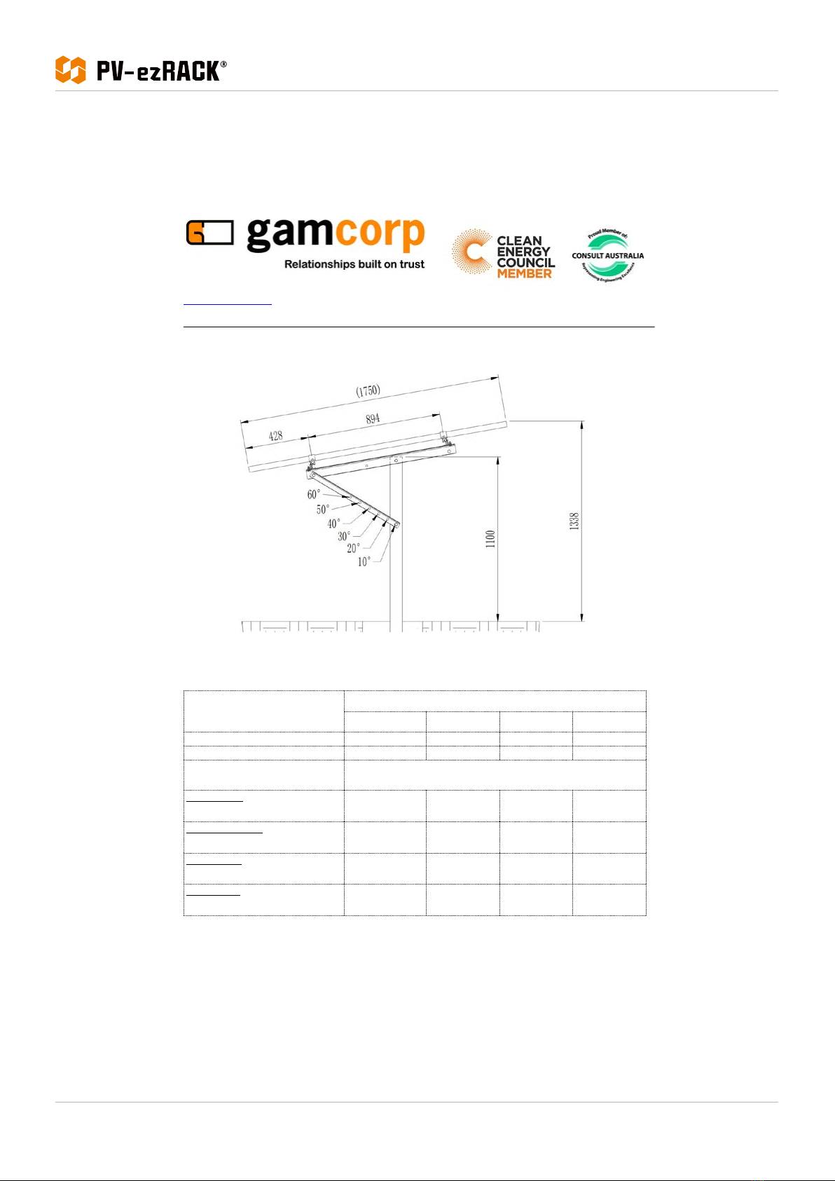
Clenergy PV-ezRack® PostMount 1-A is a ground
mounting system suitable for large scale commercial
and utility scale installations. PV-ezRack® PostMount
1-A has been developed to fit any PV module in the
outdoors and uneven ground areas. PV-ezRack®
PostMount 1-A have good compatibility for the different
region via the angle adjustment (10°~60°). Using high
quality engineered components PostMount 1-A saves
developers and installers, time and money when
delivering large scale projects.
Please review this manual thoroughly before installing
PostMount 1-A. This manual provides the following
contents:
1) Installation planning;
2) Installation instructions.
The PV-ezRack® PostMount 1-A parts, when installed in
accordance with this guide, will be structurally adequate
and meet the AS/NZS1170.2:2011 Admt 4-2016 standard.
During installation, and especially when working
on the ground, please comply with the appropriate
occupational health and safety regulations. Please also
pay attention to other relevant regulations in your local
region. Please check that you are using the latest version
of the installation manual by contacting Clenergy via
email on www.clenergy.com.cn.or contacting your local
distributor.
Product Warranty:
Please refer PV-ezRack® Product Warranty on our
website.
- Introduction -
List of contents
Product Introduction
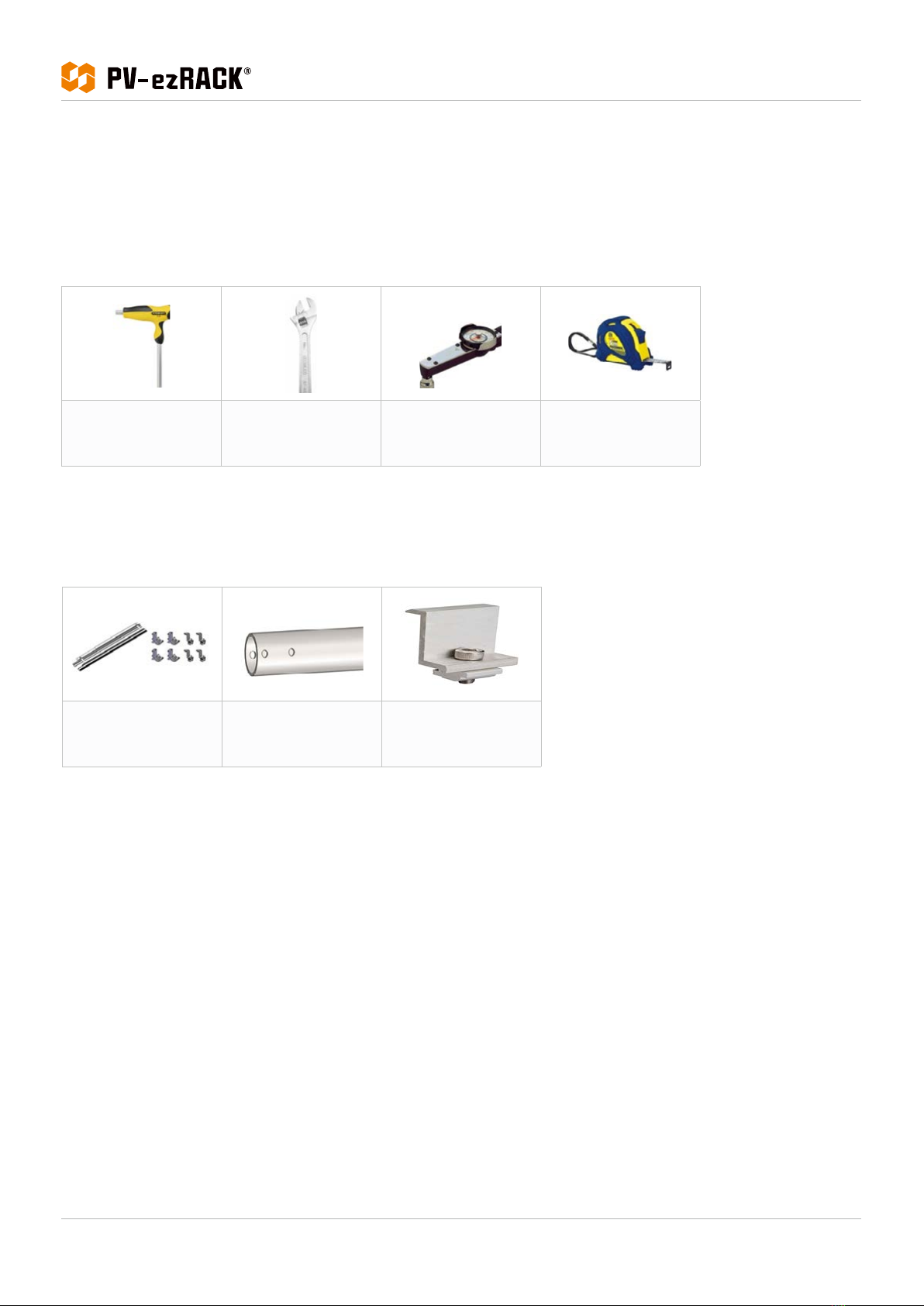
Tools & Components
System Overview
Installation Instruction
Certification
01
02
03 - 05
06 - 07
08 -10

Installation Guide / PostMount 1-A with ECO-Rail
2
Code-Compliant Planning and Installation Guide V 2.2 - Complying with AS/NZS1170.2: 2011 ADMT 4-2016
Tools and Components
Tools
Components
Allen Key 6 mm Spanner Torque Wrench 5m Tape
COP-PM1A-01
PM1-A Components
Packx1
ER-P-83/2400
Pole for PostMount 1-A,
Ø83x2400mmx1
ER-EC-ST
End Clampx4
- Tools and Components -

Installation Guide / PostMount 1-A with ECO-Rail
3Code-Compliant Planning and Installation Guide V 2.2 - Complying with AS/NZS1170.2: 2011 ADMT 4-2016 - System Overview -
System Overview
Side view drawing of PV-ezRack® PostMount 1-A is shown below. The panels tilt angle and embedment depth below
are for reference only. Please refer to Certificate Letter to obatin the certified max panels tilt angle and min embedment
depth for different wind regions and different soil types.
3
1.PM1-A Components Pack 2. PM1-A Pole, Ø83x2400mm 3. End Clamp
1. PostMount 1-A

Installation Guide / PostMount 1-A with ECO-Rail
4
Code-Compliant Planning and Installation Guide V 2.2 - Complying with AS/NZS1170.2: 2011 ADMT 4-2016
Improper operation may lead to the deadlock of bolts and nuts. Follow the steps below to reduce this risk.
Reduce the friction coefficient
(1) Ensure that the thread surface is clean (no dirt or contaminant).
(2) Apply lubricant (grease or 40# engine oil) to fasteners prior to tightening to avoid galling or seizing
in the threads.
General installation instructions
(1) Apply force to fasteners in the direction of thread.
(2) Apply force uniformly to maintain required torque.
(3) Professional tools and tool belts are recommended.
(4) Avoid using electric tools for final tightening.
(5) Avoid working at high temperatures.
- System Overview -
2. Precautionary Measures for Stainless-Steel
Fastener Installation

Installation Guide / PostMount 1-A with ECO-Rail
5Code-Compliant Planning and Installation Guide V 2.2 - Complying with AS/NZS1170.2: 2011 ADMT 4-2016 - System Overview -
Safe Torques
Please refer to safe torques defined in this guide as shown in the figure below. If power tools are required, Clenergy
recommends the use of low speed only. High speed and impact drivers increase the risk of bolt galling (deadlock). If
deadlock occurs and you need to cut fasteners, please make sure that there is no load on the fastener before you cut it.
Avoid damaging the anodized or galvanized surfaces.
All drawings and dimensions in this installation guide are for generic reference. The PV-ezRack® PostMount 1-A is to
be optimized to suit specific conditions for each project and documented in engineering drawings. As a result, major
components of the PV-ezRack® PostMount 1-A may be provided in sectional sizes and lengths that vary from those
shown in this guide. The installation operations detailed in this instruction guide remain the same regardless of the
component size. In case you need to do any on-site modifications or alteration of the system in a way that would
be different from engineering drawings, please provide marked up drawings/sketches for Clenergy’s review prior to
modification for comment and approval.
3. Installation Dimensions

Installation Guide / PostMount 1-A with ECO-Rail
6
Code-Compliant Planning and Installation Guide V 2.2 - Complying with AS/NZS1170.2: 2011 ADMT 4-2016
Installation Instructions
Dig a hole to the diameter 300-400mm and depth 1200-1400mm
highlighted in the PM1-A engineering letter. Cover the bottom of
the hole with 50-70mm gravel.
Place the pole into the middle of the hole and fill it with concrete.
Maintain the position of the post. The allowed vertical tolerance
is ±2°.Keep the axle of the 2- Ø14 holes parallel to East-West;keep
the vertical angle deviation within ±5°.For more than one system
on one site maintain all the axles of 2- Ø14 holes aligned.
1) As show in figure on the right, with M12 * 120 hex bolts and nuts
to lock Angle Steel 63*40*1010 on the Pole. And then use M12 *
120 hex bolts and nuts to lock supporting rod 40 * 40 * 682 on the
Pole.
Note: supporting rod around multiple holes which can be
adjusted by adjusting the mounting, adjustable angle of 10 °, 20 °,
30 °, 40 °, 50 ° and 60 °.
Recommended torque for M12 bolts is 40~45 N·m
Cement mortar
Gravel
- Installation Instructions -
1. Pole 83*2400 Installation
2. PostMount 1-A Kit Installation

Installation Guide / PostMount 1-A with ECO-Rail
7Code-Compliant Planning and Installation Guide V 2.2 - Complying with AS/NZS1170.2: 2011 ADMT 4-2016
2) As show in figure on the right, place the ECO-Rail on Angle Steel.
Use the Cross Connection Clamp, Cup head square neck bolts
M8*25, Hexagon nut with flange M8 to lock on the Angle Steel 63 *
40 * 1010.
Recommended torque for M8 bolts is 18~20 N·m
3) Position the PV Panel landscape by aligning the centre line
with the ECO-Rail. And fix the PV Panel to the Rails by using End
Clamps.
Recommended torque for M8 bolts is 18~20 N·m
- Installation Instructions -

Installation Guide / PostMount 1-A with ECO-Rail
8
Code-Compliant Planning and Installation Guide V 2.2 - Complying with AS/NZS1170.2: 2011 ADMT 4-2016
- Certification -
Certification
Gamcorp (Melbourne) Pty Ltd A.C.N 141 076 904 A.B.N 73 015 060 240
www.gamcorp.com.au [email protected]
Suite 4, 346 Ferntree Gully Rd, Notting Hill VIC 3168 Tel: 03 9543 2211
Our Ref: 8762-PM1A/AA
31 August 2020
CLENERGY AUSTRALIA
1/10 Duerdin St
Clayton VIC 3168
Array Frame Engineering Certificate
RE: Postmount PM1-A Installation – PV panel 1750mmx1010mm
Gamcorp (Melbourne) Pty Ltd, being Structural Engineers within the meaning of Australian
Regulations, have carried out a structural design check of the PV-ezRack Postmount PM1-A for
installation in four general soil types within Australia and New Zealand. The design check has
been based on the drawings of the system and its components, and other documents and
information, provided by CLENERGY AUSTRALIA.
Part No. Part Name Description
13-11011-004 ER-EC-ST PV-ezRack Standard End clamps
ER-R-ECO PV-ezRack ECO Rail 1100mm
13-16041-001 Left and right supporting beam, angle steel
63*40*1010
13-16041-002 Left and right supporting rod, angle steel
40*40*682
13-15010-054 ER-P-83/2400 PV-ezRakc, Pipe ø83*2400mm (PM1-A)
We find the Postmount PM1-A to be structurally sufficient for the proposed installation, based
on the following conditions:
•Wind Loads according to AS/NZ1170.2:2011 (R2016):
◦Wind Terrain Category 2;
◦Wind average recurrence interval of 100 years for ultimate state and 25 years for
serviceability;
◦Wind region A, B, C & D;
◦Md=1, Ms=1 & Mt=1;
•Max. Solar Panel length 1750mmx1010mm;
•Steel members to be Q235B;
•Aluminium members to be AL6005-T5;
•Bolts to be SUS304;
•The certification excludes assessment of PV panels
•Refer to Table 1 for maximum tilt angle and footing options;
•Dimensions as shown here on the picture;
ISO 9001:2008 Registered Firm
Certificate No: AU1222
8762 - Compliance Letter PM1-A - calc4.2.odt
Page 1 of 3

Installation Guide / PostMount 1-A with ECO-Rail
9Code-Compliant Planning and Installation Guide V 2.2 - Complying with AS/NZS1170.2: 2011 ADMT 4-2016 - Certification -
Gamcorp (Melbourne) Pty Ltd A.C.N 141 076 904 A.B.N 73 015 060 240
www.gamcorp.com.au [email protected]
Suite 4, 346 Ferntree Gully Rd, Notting Hill VIC 3168 Tel: 03 9543 2211
Table 1 – Maximum Tilt Angle and Footing Options
Wind Region
Region A Region B Region C Region D
W
i
n
d
s
p
e
e
d
(
m
/
s
)
4
1
4
8
5
9
7
3
M
a
x
i
m
u
m
t
i
l
t
a
n
g
l
e
(
°
)
6
0
6
0
5
0
2
0
Soil Type Post embedded in concrete pier:
300 mm diameter concrete piers minimum depth (m)
Hard class soil
[Gravels; dry (hard) clays]
0.80 0.90 1.00 0.80
Very Firm class soil
[Dry (stiff) clays; clayey sands; coarse
sands; compact sands]
0.85 0.95 1.10 0.85
Firm class soil
[Damp clays; sandy clays; damp sands]
0.95 1.05 1.20 0.95
Soft class soil
[Wet clays; silty loams; wet or loose sands]
1.15 1.25 1.40 1.15
ISO 9001:2008 Registered Firm
Certificate No: AU1222
8762 - Compliance Letter PM1-A - calc4.2.odt
Page 2 of 3

Installation Guide / PostMount 1-A with ECO-Rail
10
Code-Compliant Planning and Installation Guide V 2.2 - Complying with AS/NZS1170.2: 2011 ADMT 4-2016
- Certification -
Gamcorp (Melbourne) Pty Ltd A.C.N 141 076 904 A.B.N 73 015 060 240
www.gamcorp.com.au [email protected]
Suite 4, 346 Ferntree Gully Rd, Notting Hill VIC 3168 Tel: 03 9543 2211
Notes:
1. This certification is applicable for the Postmount PM1-A with dimensions as
shown in this letter.
2. Other piers dimensions are possible, contact Gamcorp, if required.
3. Panel weight calculated: 20kg.
4. Embedment depth is relevant for soils, having adhesion capacity from 300mm
of the ground level; in other cases contact Gamcorp.
5. For concrete piers foundation, use 25 MPa strength concrete (minimum). It is
recommended to insert N12 bar 200mm long at the bottom of the post into the
concrete piers.
6. If any of the above conditions cannot be met, the structural engineer must be
notified immediately.
Construction is to be carried out strictly in accordance with the manufacturers instructions and
site soil report recommendations. This work was designed by Ali Askari in accordance with the
provisions of relevant Regulations and in accordance with sound, widely accepted engineering
principles.
Yours faithfully,
Gamcorp (Melbourne) Pty Ltd
L. van Spaandonk
Principal Engineer
FIEAust Cpeng NER
ISO 9001:2008 Registered Firm
Certificate No: AU1222
8762 - Compliance Letter PM1-A - calc4.2.odt
Page 3 of 3

Clenergy
1/10 Duerdin St
Clayton VIC 2168
Australia
Phone: +61 3 9239 8088
Email: sales@clenergy.com.au
Web: www.clenergy.com.au
@Clenergy@Clenergy_global
@ClenergyClub@Clenergy
@ClenergyGlobal / @ClenergyClub / ClenergyAUS
A Clenergy Technologies Company
Table of contents
Other PV-ezRack Solar Panel manuals
Popular Solar Panel manuals by other brands

JIANGYIN TITANERGY
JIANGYIN TITANERGY TT-ADJUSTABLE TILT LEGS installation manual

BIRDBOGGLE
BIRDBOGGLE SOLAR POWERED SCARECROW quick start guide

Paua
Paua Air 300 Assembly instruction

ET Solar
ET Solar ET SOLAR Series installation manual

REC
REC N-PEAK Series installation instructions

Campbell
Campbell SP10 instruction manual

GEM
GEM 2881506 quick start guide

Sunrise
Sunrise Aquaman SR-54MNHLPro Installation and operation manual

Thunderbolt Magnum Solar
Thunderbolt Magnum Solar 57970 Owner's manual & safety instructions

Solon
Solon Black 160/05 Assembly and installation instructions

Thermo King
Thermo King ThermoLite T-Series installation guide

Sunforce
Sunforce 130 WATT CRYSTALLINE SOLAR PANEL user manual