Installation Guide / SolarRoof Pro 2.0 Installation Guide / SolarRoof Pro 2.0
12
Code-Compliant Planning and Installation Guide V1.0 - Complying with Eurocodes 0-9 and VDI 6012 Code-Compliant Planning and Installation Guide V1.0 - Complying with Eurocodes 0-9 and VDI 6012
Introduction
Complying with all applicable local or national
building codes, including any that may supersede this
manual;
Ensuring that PV-ezRack and other products are
appropriate for the particular installation and the
installation environment;
Using only PV-ezRack parts and installer-supplied
parts as specified by the PV-ezRack project plan.
(substitution of parts may void the warranty and
invalidate the letter of certification);
Recycling: Recycle: according to the local relative
statute.
Removal: Reverse installation process.
Ensure that there are no less than two professionals
working on panel installation.
Ensure the installation of related electrical equipment
is performed by licenced electricians.
Ensuring safe installation of all electrical aspects of
the PV array.
Ensuring that the roof, its rafters/purlins, connections,
and other structural support members can support
the array under building live load conditions;
Ensuring that screws to fix interfaces have adequate
pull-out strength and shear capacities as installed;
Maintaining the waterproof integrity of the roof,
including selection of appropriate flashing;
The installation need to comply with the regulations
of the German Central Association of Roofers (ZVDH)
for work on roofs.
During the installation of supporting system, module
installation shall take full consideration of fire risks.
Please read and understand the solar module
installation manual before system installation.
For more regulations of the German Professional
Association, see:
BGV A1-General rules
BGV A2-Power Systems and Equipment
BGV C22-Construction work
•
•
•
•
•
•
•
•
•
•
•
•
•
•
List of contents
Introduction
System Specifications
Tools & Component
System Overview
Installation Instruction
Alu Hook Installation
01
02
03
04
06
08
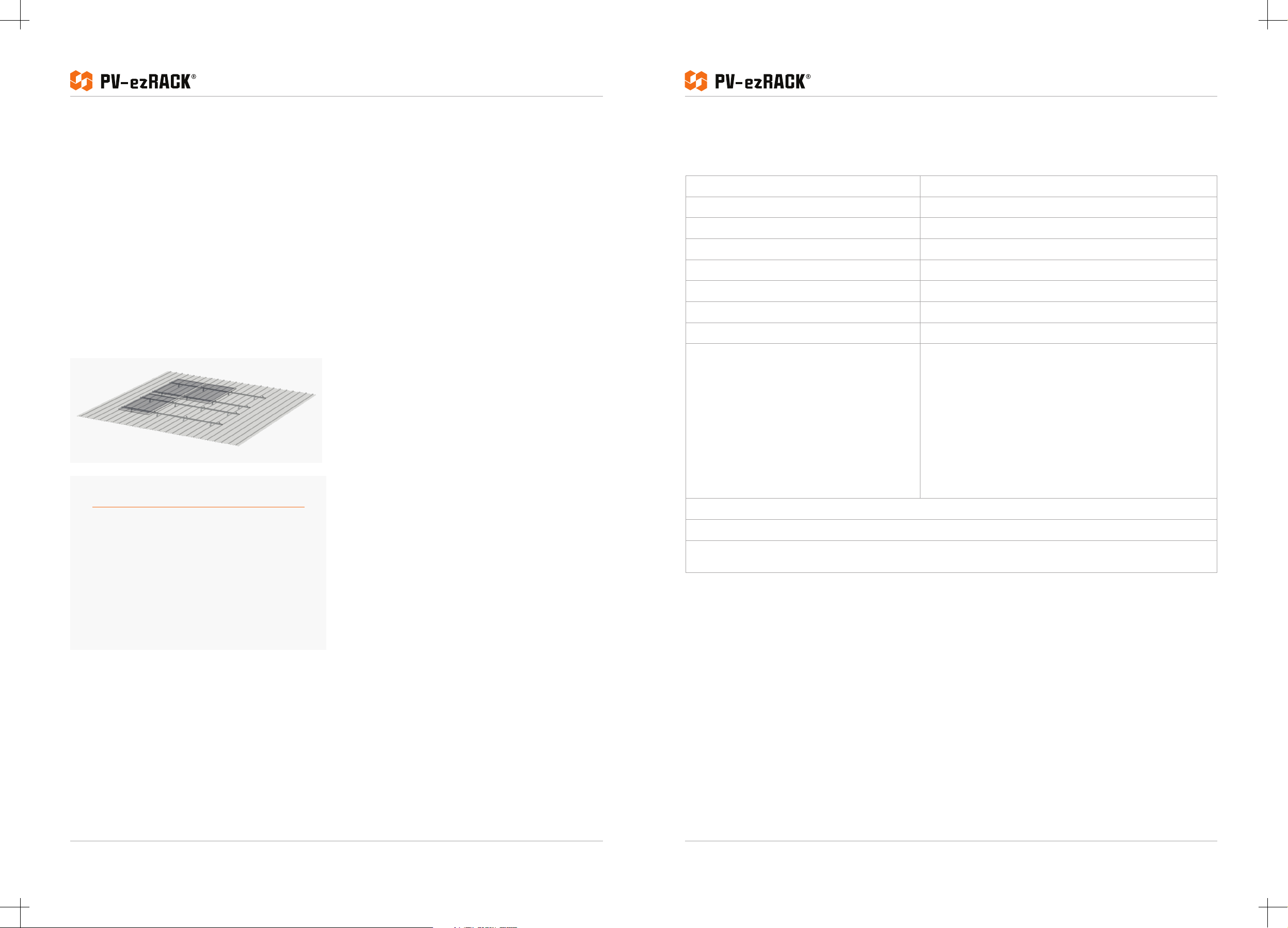
The Clenergy PVezRack® SolarRoof Pro 2.0 is a roof-
mounting solution suitable for most residential pitched
roofs. Using our innovative rail, M module, and interface
family, the SRP2.0 delivers a quick, safe, and cost
effective solution for installers.
Please review this manual thoroughly before installing
PVezRack® SolarRoof Pro 2.0. This manual provides:
1) Supporting documentation for building permit
applications relating to PVezRack® SolarRoof Pro 2.0 PV
Module Mounting System,
2) Planning and installation instructions.
The PVezRack® SolarRoof Pro 2.0 parts, when installed
in accordance with this guide, will be structurally sound
and will meet the Eurocodes and VDI 6012 standard.
During installation, and especially when working on the
roof, please comply with the appropriate Occupational
Health and Safety regulations. Please also pay attention
to any other relevant State or Federal regulations.
Please check that you are using the latest version of the
Installation Manual, which you can do by contacting
Clenergy via email on sales@clenergy.com.
- Introduction -
The installer is solely responsible for: Roof Angle 15-60 degrees
Building Height <=12m
Wind Zone Wind zone 1 to wind zone 4
Snow Zone Snow zone 1 to snow zone 3
Max Altitude According to the calculation report
Max Span Width According to the calculation report
Min distance for wood screws from wood edges According to EN 1995-1-1
Manufacture Clenergy Technology Co., Ltd.
Design Standards BS EN 1990:2002 Basis of Structural Design;
DIN EN 1991-1-4. Eurocode 1: Actions on structures - Part 1-4:
General actions - Wind actions;
DIN EN 1991-1-3 : 2004 EUROCODE 1: ACTIONS ON
STRUCTURES - PART 1-3: GENERAL ACTIONS - SNOW LOADS;
VDI 6012 Blatt 1.4 Integration of decentralised and regenerative
energy systems in buildings;
EN 1995-1-1: Eurocode 5: Design of timber structures;
DIN 1055-4:2006:Eurocode3 Design of Steel structures -Part 1- 8:
Design of joints;
DIN 1055-5:2006: Actions on structures-Part5: Snow loads and
ice loads.
All wood fasteners need to follow the local building regulations, e.g. DIN 1052
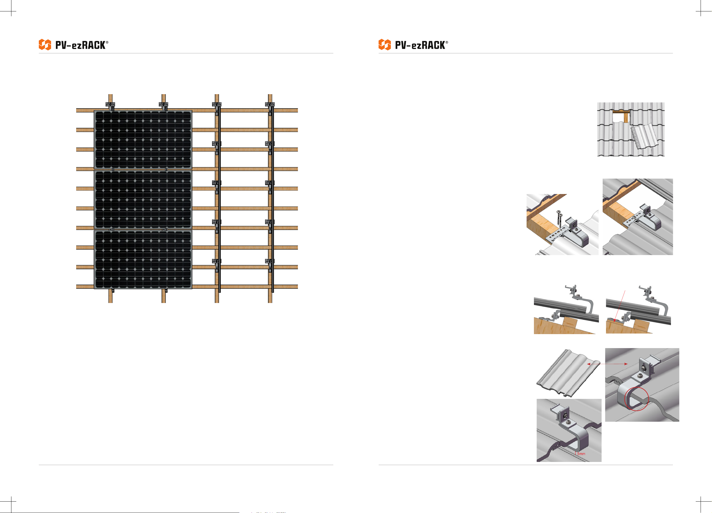
Only approved and certified wood screws are to be used for roof hook installations
The hooks can only be mounted on the roof rafters but not on the roof lath (the horizontal wood beams that hold
the tiles)
Note:
Snow zone 1, altitude above the sea level up to 500m;
Snow zone 2, altitude above the sea level up to 285m;
Snow zone 3, altitude above the sea level up to 255m;
Wind zone 1, Inland, the height of building less than 12m;
Wind zone 2, Inland, coastal and island of the Baltic Sea; the height of building less than 12m;
Wind zone 3, Inland, coast and islands of the Baltic Sea; the height of building less than 12m;
Wind zone 4, Inland, coast of the North and Baltic Seas and islands of the Baltic Sea; the height of building less than
12m.
System Specifications
- System Specifications -