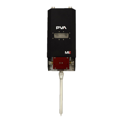
PVA MR1 User manual

143B
MR1
Owner’s Manual
Revision B
WHERE
PRECISION
DRIVES
PRODUCTION

MR1 Manual
Revision B /June 2021
Page 2 of 33
144BThis document is based on information available at the time of its publication. While efforts
have been made to ensure the contents of this manual are accurate, the information
contained herein does not purport to cover all specific details or variations in hardware, or
to provide for every possible contingency in connection with installation, operation, or
maintenance. Features may be described herein which are not present in all hardware and
software systems. Precision Valve and Automation, Inc. assumes no obligation of notice to
holders of this document with respect to changes subsequently made.
145BPrecision Valve and Automation, Inc. makes no representation or warranty, expressed,
implied, or statutory with respect to, and assumes no responsibility for the accuracy,
completeness, sufficiency, or usefulness of the information contained herein. No warranties
of merchantability or fitness for purpose shall apply.
146BThis document, including the information contained herein, is the property of
Precision Valve and Automation, Inc. and is considered confidential and proprietary
information. It is delivered on the express condition that it not be used, disclosed, or
reproduced, in whole or in part, for any reason without prior written consent of
Precision Valve and Automation, Inc.
147BCopyright © 2021
148BPrecision Valve and Automation, Inc.
149BAll Rights Reserved.

MR1 Manual
Revision B /June 2021
Page 3 of 33
306BTable of Contents
280B
Introduction...........................................................................................................4
PVA Contact Information ........................................................................................................4
Document History.....................................................................................................................4
Safety ..........................................................................................................................................5
Theory of Operation .................................................................................................................7
Personal Protective Equipment.............................................................................................7
Waste Disposal...........................................................................................................................7
Necessary Tools ........................................................................................................................7
Spare Parts Kit...........................................................................................................................7
Setup.......................................................................................................................8
Overview .................................................................................................................................... 8
Operation................................................................................................................9
Bleed the Pump.........................................................................................................................9
Shutdown ...................................................................................................................................9
Remove the Pump ....................................................................................................................9
Disassembly ..............................................................................................................................11
Assembly Instructions...........................................................................................................16
Install Clamp.....................................................................................................................21
Fill the Fluid Distribution Block ................................................................................... 22
Install the MR1................................................................................................................. 23
Technical Specifications....................................................................................26
Troubleshooting..................................................................................................27
Damaged Pump Gasket ........................................................................................................ 28
Calling Technical Support .................................................................................................... 30
Notes ..................................................................................................................... 31
Warranty ...............................................................................................................32
Table of Figures ...................................................................................................33

MR1 Manual
Revision B /June 2021
Page 4 of 33
Introduction
150BBefore you operate this system, read the operation and setup manual. This will help you to
become familiar with the product and ensure successful operation.
151BIf any questions or problems arise, contact PVA’s Technical Support department.
PVA Contact Information
152BMain Office PVA
153BOne Mustang Drive
154BCohoes, NY 12047
155BTel +1-518-371-2684
156BFax +1-518-371-2688
157BWebsite: http://www.pva.net
159BTechnical Support
160BTel +1-844-734-0209
Document History
Revision
Revision Date
Reason for Changes
REV B
June 2021
Spare Parts Update
REV A
March 2020
Initial Release
234BNote: All photographs and CAD model representations in this document are a
“general representation” of the system and its components. The actual appearance
of the system and its components can differ based upon customer specific
configuration.

MR1 Manual
Revision B /June 2021
Page 5 of 33
Safety
162BCertain warning symbols are affixed to the machine and correspond to notations in this
manual. Before operating the system, identify these warning labels and read the notices
described below. Not all labels may be used on any specific system.
Always wear approved safety glasses when you operate or work near the
workcell.
Before you operate the system, read and understand the manuals provided
with the unit.
Never put hands or tools in areas with this symbol when the machine is in
operation. A dangerous condition may exist.
Read and understand the manuals provided with the unit before any repairs
or maintenance is done. Only a qualified individual should do service.
Use caution when there are pressurized vessels. Find and repair any leaks
immediately. Always wear appropriate safety equipment when you work
with pressurized vessels or vessels that contain chemicals
Shear hazard from moving parts. Avoid contact.
Do not remove protective guarding.
In situations where inattention could cause either personal injury or damage
to equipment, a warning notice is used.

MR1 Manual
Revision B /June 2021
Page 6 of 33
Do not smoke near the machine. Always have a fire extinguisher available
for emergency use.
Before performing any repairs or maintenance to the system, turn off power
and lock out the power disconnect switch.
Warning notices are used to emphasize that hazardous voltages, current,
temperatures, or other conditions that could cause personal injury exist in
this equipment or may be associated with its use. Only qualified personnel
should enter areas designated with this symbol.
Laser light source present. Do not stare directly into the beam. Do not use in
the presence of highly reflective surfaces
Pinch hazard from moving parts. Avoid contact.
Hot surface. Avoid contact.
Warning, Ultraviolet (UV) light hazard. Do not look directly at the UV light
source.

MR1 Manual
Revision B /June 2021
Page 7 of 33
Theory of Operation
163BThe MR1 is a servo-controlled piston dispenser for processing single component materials.
Personal Protective Equipment
164BOperators must use eye protection because material contents are under pressure. Always
wear gloves when handling materials and solvents. Refer to MSDS sheets on the material
being dispensed for other precautions.
Waste Disposal
165BDispose of all used parts and materials in accordance with local laws and regulations.
Necessary Tools
166BPVA offers tools and cleaning accessories to maintain the MR1.
167BPart Number
168BDescription
169B02506
170BHook and Pick Set
171BSoft-jaw Pliers and/or Vice
172BLubrication Fluid
173BSilicone Grease
174B2.5 mm and 3 mm T-handle or Hex Key
175B90° Snap Ring Pliers
1BTable 1: MR1 Tool Kit
Spare Parts Kit
Part Number
Description
612-12676-1
Soft Seals (Does not include diaphragm)
614-15553-1
Diaphragm
Table 2: Spare Parts Kit

MR1 Manual
Revision B /June 2021
Page 8 of 33
Setup
176BBefore you operate the MR1 metered piston dispenser, read and understand this manual.
This information is for safety and correct operation of the pump. This manual provides the
information needed to operate, repair, and troubleshoot.
Overview
177BThe MR2 metered piston dispenser is constructed from three main components.
•71BThe upper section of the pump is called the metering body; it houses the carbide
cylinder and piston.
•72BOn the front of the metering body is the oil window and fluid distribution block which
are used to ensure the pistons function smoothly.
•73BThe lower section of the pump is called the metering sleeve which is covered by the
air body that controls the flow of dispensed material.
178B
2BFigure 1: MR1 Overview

MR1 Manual
Revision B /June 2021
Page 9 of 33
Operation
235BNote: Use only compatible solvents and materials or the seals and O-rings will be
damaged.
Bleed the Pump
1. 74BTo bleed the MR1, move the pump over a purge cup.
2. 75BDispense all the way until the piston reaches its full travel. Repeat as many times as
necessary to get all air out of the system.
Shutdown
179BRefer to the workcell manual for information on how to shut down the workcell.
1. 76BReduce the air pressure in the system to zero.
2. 77BBleed the pressure out of the pump and install the nightcap. Make sure to wipe off
any excess material before screwing on nightcap.
Remove the Pump
1. 78BBefore you remove the MR1 from the material supply system, use the purge button to
dispense until the piston is all the way down.
2. 79BEngage the workcell Emergency Stop button and turn the air pressure to 0 psi.
WARNING: MR1 maximum air pressure is 75 psi. Do not overpressure the air system.
3. 80BRemove the air lines, fluid lines, and motor cables.
4. 81BTo remove the pump, use a 4 mm hex wrench to remove the four mounting bolts.
180B
3BFigure 2: Remove Mounting Bolts

MR1 Manual
Revision B /June 2021
Page 10 of 33
236BWARNING: Keep the MR1 upright until all fluid is removed from the oil window or oil will
spill from the oil window. See Figure 17: Oil Window.
5. 82BTo remove the fluid section from the drive assembly, remove the airlines.
6. 83BUse a 3 mm hex wrench to remove the four shoulder bolts from the fluid assembly
mount plate.
7. 84BUse a 3 mm hex wrench to remove the four socket head bolts from the fluid
assembly mount plate.
181B
4BFigure 3: Shoulder and Socket Bolts
8. 85BSeparate the pump from the drive assembly mount.
182B
5BFigure 4: Remove Pump from Drive Assembly

MR1 Manual
Revision B /June 2021
Page 11 of 33
9. 86BRemove the breather vent from the metering body and remove the lubrication fluid
from the oil window.
183B
6BFigure 5: Breather Vent
Disassembly
1. 87BTurn the wing screw counterclockwise to loosen it. Remove the clamp and fitting. Do
not lose the clamp adaptor seals.
184B
7BFigure 6: Clamp and Sanitary Fitting Removed
2. 88BUse a 3 mm hex wrench to remove the six socket head bolts from the air section.
185B
8BFigure 7: Remove Bolts from Air Section

MR1 Manual
Revision B /June 2021
Page 12 of 33
3. 89BRemove the air section from the fluid section.
186B
9BFigure 8: Remove Air Section from Fluid Section
4. 90BThe gasket is the black mat under the air body. Remove the gasket and clean it.
187B
10BFigure 9: Remove Gasket
5. 91BExamine the gasket for any cracks or signs of wear on the side that faces the
metering sleeve. If the gasket is worn, replace it. DO NOT flip the gasket over, or you
can damage the pump.
188B
11BFigure 10: Worn Pump Gasket

MR1 Manual
Revision B /June 2021
Page 13 of 33
6. 92BIf there is any material inside the pump, push the metering piston all the way down
to remove it.
7. 93BUse a 3 mm hex wrench to remove the four socket head bolts from the fluid
distribution block.
189B
12BFigure 11: Remove Socket Head Bolts
8. 94BPull the fluid distribution block out of the metering body.
190B
13BFigure 12: Separate Fluid Distribution Block from Metering Body
9. 95BPull the metering sleeve out of the metering body to remove it.
191B
14BFigure 13: Remove Metering Sleeve from Metering Body

MR1 Manual
Revision B /June 2021
Page 14 of 33
10. 96BRemove the metering piston from the metering sleeve.
192B
15BFigure 14: Remove Metering Piston from Metering Sleeve
11. 97BPlace an adjustable wrench on the flat part of the metering piston.
193B
16BFigure 15: Adjustable Wrench on Flats
12. 98BUse a flathead screwdriver to turn the screw counterclockwise and remove the lip
seal screw.
194B
17BFigure 16: Remove Lip Seal Screw

MR1 Manual
Revision B /June 2021
Page 15 of 33
13. 99BSeparate the metering piston, washer, lip seal, and screw.
195B
18BFigure 17: Lip Seal Screw, Teflon Washer, Metering Piston Disassembled
14. 100BUse a 2.5 mm hex wrench to remove the six button head screws from oil window.
Clean any remaining oil or material from the oil window.
196B
19BFigure 18: Oil Window
15. 101BClean all of the necessary parts.
237BNote: If threads are not cleaned properly, the fittings will bind. Ensure that threads
are clean before proceeding with assembly.
238BNote: Do not leave material on any of the pump components.

MR1 Manual
Revision B /June 2021
Page 16 of 33
Assembly Instructions
1. 102BPut the pump gasket on the air section.
197B
20BFigure 19: Place Pump Gasket on Air Section
2. 103BPlace the air section on the fluid section. Make sure that the air ports and fluid inlet
are on the same side.
198B
21BFigure 20: Align Air Ports and Fluid Inlets

MR1 Manual
Revision B /June 2021
Page 17 of 33
3. 104BLay the air and fluid sections flat. Use a 3 mm hex wrench to install the six socket
head bolts onto the air section. Tighten the bolts in a cross pattern until tight.
199B
22BFigure 21: Install Socket Head Bolts on Air Section
4. 105BApply silicone grease to the O-ring side of the lip seal.
5. 106BInstall the lip seal on the screw.
6. 107BInstall washer on top of the lip seal. Apply pressure to push on the washer until it is
fully engaged. You will hear a small “click”.
7. 108BInstall the screw onto the metering piston. Tighten the screw until it is fully
engaged.
200B
23BFigure 22: Install Lip Seal, Washer, Screw

MR1 Manual
Revision B /June 2021
Page 18 of 33
8. 109BApply silicone grease to the O-rings and install one in each end of the metering
sleeve.
201B
24BFigure 23: Metering Sleeve with O-rings Installed
9. 110BCarefully install the metering sleeve into the metering body.
202B
25BFigure 24: Install Metering Sleeve into Metering Body

MR1 Manual
Revision B /June 2021
Page 19 of 33
10. 111BInstall the metering piston into the metering sleeve.
203B
26BFigure 25: Install Metering Piston
11. 112BPush the metering piston through the metering body with your finger. The end of
the piston will come through the top of the metering body.
204B
27BFigure 26: Install Metering Piston

MR1 Manual
Revision B /June 2021
Page 20 of 33
12. 113BAlign the air and fluid body pins with the metering body.
13. 114BInstall two M4x80 bolts on top of the air fluid distribution body and two M4x40 bolts
on the bottom.
205B
28BFigure 27: Install M4x80 bolts
14. 115BUse an adjustable wrench install the needle.
206B
29BFigure 28: Install Needle
Other manuals for MR1
1
Table of contents
Other PVA Dispenser manuals
Popular Dispenser manuals by other brands

ViscoTec
ViscoTec preeflow eco-DUO330 Operation & maintenance manual

Greenway Home Products
Greenway Home Products GWF8 Use & care guide

Curtis
Curtis TCC2N instructions

Technical Concepts
Technical Concepts OneShot Plus installation instructions

Franke
Franke XINX625 Installation and operating instructions

Sanela
Sanela SLZN 83ER6 Instructions for use