PVA MR2 User manual

MR2
Owner’s Manual
Revision B
WHERE
PRECISION
DRIVES
PRODUCTION

MR2 Manual
Revision B /June 2021
Page 2 of 34
This document is based on information available at the time of its publication. While efforts
have been made to ensure the contents of this manual are accurate, the information
contained herein does not purport to cover all specific details or variations in hardware, or
to provide for every possible contingency in connection with installation, operation, or
maintenance. Features may be described herein which are not present in all hardware and
software systems. Precision Valve and Automation, Inc. assumes no obligation of notice to
holders of this document with respect to changes subsequently made.
Precision Valve and Automation, Inc. makes no representation or warranty, expressed,
implied, or statutory with respect to, and assumes no responsibility for the accuracy,
completeness, sufficiency, or usefulness of the information contained herein. No warranties
of merchantability or fitness for purpose shall apply.
This document, including the information contained herein, is the property of
Precision Valve and Automation, Inc. and is considered confidential and proprietary
information. It is delivered on the express condition that it not be used, disclosed, or
reproduced, in whole or in part, for any reason without prior written consent of
Precision Valve and Automation, Inc.
Copyright © 2019
Precision Valve and Automation, Inc.
All Rights Reserved.

MR2 Manual
Revision B /June 2021
Page 3 of 34
Table of Contents
Introduction..................................................................................................................................4
PVA Contact Information.........................................................................................................................................4
Document History .....................................................................................................................................................4
Safety...........................................................................................................................................................................5
Theory of Operation .................................................................................................................................................. 7
Personal Protective Equipment ............................................................................................................................. 7
Waste Disposal ........................................................................................................................................................... 7
Necessary Tools......................................................................................................................................................... 7
Spare Parts Kit ........................................................................................................................................................... 7
Setup .............................................................................................................................................8
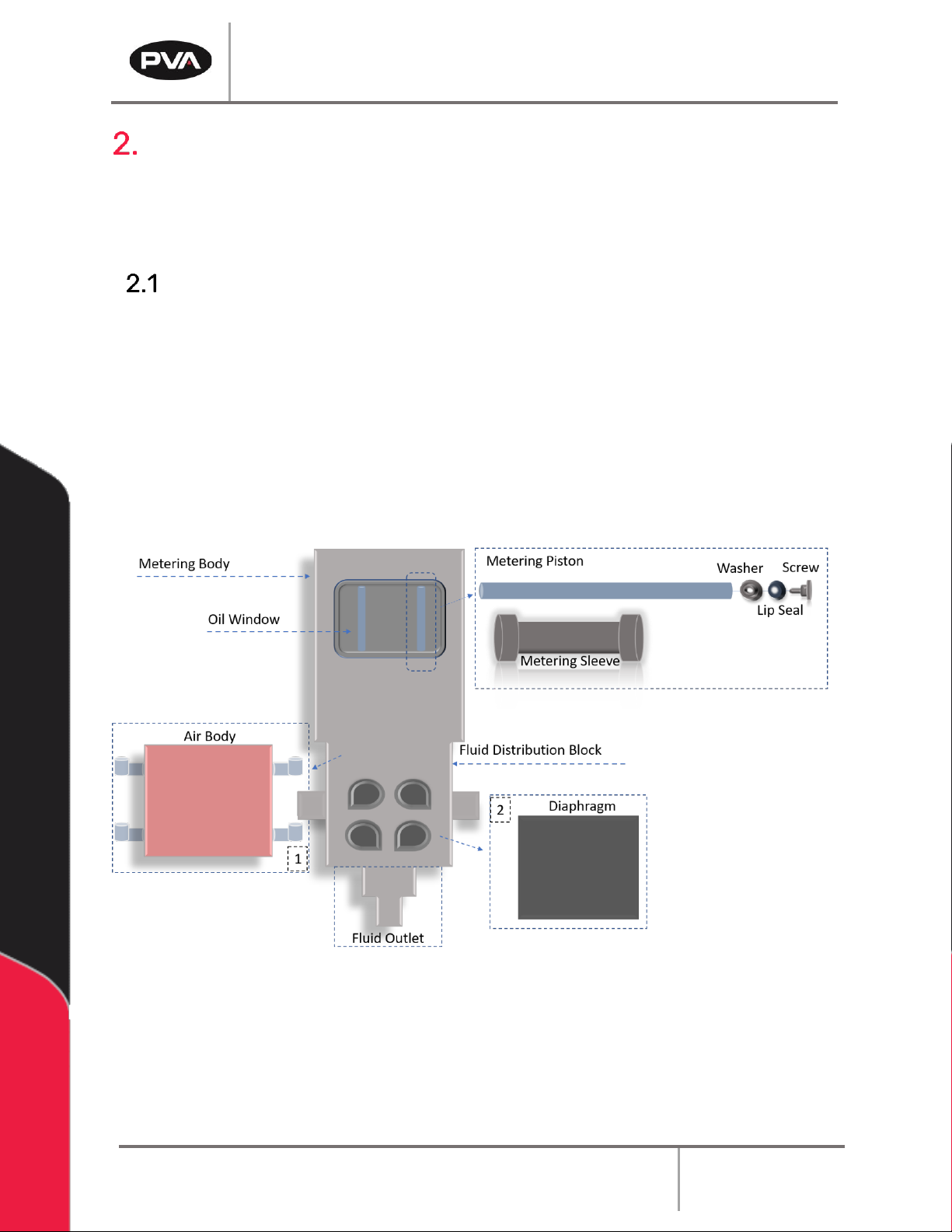
Overview......................................................................................................................................................................8
Operation.......................................................................................................................................9
Bleed the Pump .........................................................................................................................................................9
Shutdown....................................................................................................................................................................9
Disassembly................................................................................................................................................................9
Assembly Instructions............................................................................................................................................ 15
Bottom Fluid Section .................................................................................................................................... 15
Metering Piston Assembly ...........................................................................................................................18
Metering Sleeve ............................................................................................................................................. 19
Fill the Fluid Distribution Block .................................................................................................................. 25
Install the MR2............................................................................................................................................... 26
Maintenance ...............................................................................................................................27
Spare Parts .................................................................................................................................27
Technical Specifications .......................................................................................................... 28
Troubleshooting ........................................................................................................................ 28
Damaged Valve Gasket ......................................................................................................................................... 29
Worn O-Ring ............................................................................................................................................................ 30
Calling Technical Support..................................................................................................................................... 30
Notes............................................................................................................................................ 31
Warranty..................................................................................................................................... 32
Table of Figures ......................................................................................................................... 33

MR2 Manual
Revision B /June 2021
Page 4 of 34
Introduction
Before you operate this system, read the operation and setup manual. This will help you to
become familiar with the product and ensure successful operation.
If any questions or problems arise, contact PVA’s Technical Support department.
PVA Contact Information
Main Office PVA
One Mustang Drive
Cohoes, NY 12047
Tel +1-518-371-2684
Fax +1-518-371-2688
Website: http://www.pva.net
Technical Support
Tel +1-844-734-0209
Document History
Revision
Revision Date
Reason for Changes
REV B
June 2021
Spare Parts Kit
REV A
January 2020
Initial Release
Note: All photographs and CAD model representations in this document are a “general
representation” of the system and its components. The actual appearance of the
system and its components can differ based upon customer specific configuration.

MR2 Manual
Revision B /June 2021
Page 5 of 34
Safety
Certain warning symbols are affixed to the machine and correspond to notations in this
manual. Before operating the system, identify these warning labels and read the notices
described below. Not all labels may be used on any specific system.
Always wear approved safety glasses when you operate or work near the
workcell.
Before you operate the system, read and understand the manuals provided
with the unit.
Never put hands or tools in areas with this symbol when the machine is in
operation. A dangerous condition may exist.
Read and understand the manuals provided with the unit before any repairs
or maintenance is done. Only a qualified individual should do service.
Use caution when there are pressurized vessels. Find and repair any leaks
immediately. Always wear appropriate safety equipment when you work
with pressurized vessels or vessels that contain chemicals
Shear hazard from moving parts. Avoid contact.
Do not remove protective guarding.
In situations where inattention could cause either personal injury or damage
to equipment, a warning notice is used.

MR2 Manual
Revision B /June 2021
Page 6 of 34
Do not smoke near the PVA UV cure machine. Always have a fire
extinguisher available for emergency use.
Before performing any repairs or maintenance to the system, turn off power
and lock out the power disconnect switch.
Warning notices are used to emphasize that hazardous voltages, current,
temperatures, or other conditions that could cause personal injury exist in
this equipment or may be associated with its use. Only qualified personnel
should enter areas designated with this symbol.
Laser light source present. Do not stare directly into the beam. Do not use in
the presence of highly reflective surfaces
Pinch hazard from moving parts. Avoid contact.
Hot surface. Avoid contact.
Warning, Ultraviolet (UV) light hazard. Do not look directly at the UV light
source.

MR2 Manual
Revision B /June 2021
Page 7 of 34
Theory of Operation
The MR2 has a dual piston system and can process 2K materials with mix ratios up to 15:1.
For 1K chemistries, the MR2 alternates metering chambers to reduce refill time and increase
throughput. Each metering chamber is controlled independently so the mix ratio and flow
rate can be changed at the application point.
Personal Protective Equipment
Operators must use eye protection because material contents are under pressure. Always
wear gloves when handling materials and solvents. Refer to MSDS sheets on the material
being dispensed for other precautions.
Waste Disposal
Dispose of all used parts and materials in accordance with local laws and regulations.
Necessary Tools
PVA offers tools and cleaning accessories to maintain the MR2.
Part Number
Description
02506
Hook and Pick Set
Soft-jaw Pliers and/or Vice
Lubrication Fluid
Silicone Grease
2.5mm and 3mm T-handle or Hex Key
90° Snap Ring Pliers
Figure 1: MR2 Tool Kit
Spare Parts Kit
Part Number
Description
612-12675-1
Soft Seals (Does not include diaphragm)
614-12157-1
Diaphragm
Figure 2: Spare Parts Kit

MR2 Manual
Revision B /June 2021
Page 8 of 34
Setup
Before you operate the MR2 Metered Piston Dispenser, read and understand this manual.
This information is for safety and correct operation of the valve. This manual provides the
information needed to operate, repair, and troubleshoot.
Overview
The MR2 Metered Piston Dispenser is constructed from three main components.
•The upper section of the valve is called the metering body; it houses the carbide
cylinders and pistons.
•On the front of the metering body is the oil window and fluid distribution block which
are used to ensure the pistons function smoothly.
•The lower section of the valve is called the metering sleeve which is covered by the
air body that controls the flow of dispensed material.
Figure 3: MR2 Overview

MR2 Manual
Revision B /June 2021
Page 9 of 34
Operation
Note: Use only compatible solvents and materials or the seals and O-rings will be
damaged.
Bleed the Pump
1. To bleed the MR2, dispense all the way until the rods reach their full travel.
2. Repeat this five times to get all air out of the system.
Shutdown
Refer to the workcell manual for information on how to shut down the workcell.
1. Move the valve over a purge cup and reduce the pressure in the system to zero.
2. Bleed the pressure out of the valve and install the nightcap. Make sure to wipe off any
excess material before screwing on nightcap. If there are two materials, do not mix
them or they will cure.
Disassembly
1. Before you remove the MR2 from the material supply system, purge the material or
manually empty and do not refill. Make sure the pistons are all the way down.
2. Engage the workcell Emergency Stop button.
3. Turn the material and air pressure to 0 psi.
4. Remove the MR2 from the material supply and dispense systems.
5. Use a 2.5 mm hex key to remove the eight M4x12 button head screws in the oil
window.
Figure 4: Remove Oil Window Screws

MR2 Manual
Revision B /June 2021
Page 10 of 34
6. Remove any lubrication fluid in the fluid distribution block.
7. Examine the oil window gasket for any signs of wear or damage. Replace the gasket
if there are signs of wear.
8. Use a 3 mm hex key to remove the six M4x16 bolts on the front of the air body.
Figure 5: Remove the Air Body Bolts
9. Remove the air body.
10. If necessary, remove the valve stop.
Figure 6: Remove the Valve Stop
11. Remove the inlet and outlet pistons from the air body.
Figure 7: Remove and Clean the Pistons
12. Clean the air body and the pistons.
13. Examine the piston O-rings for wear. If they are worn, replace them.

MR2 Manual
Revision B /June 2021
Page 11 of 34
14. The valve gasket is the black mat under the air body. Remove the valve gasket and
clean it.
15. Examine the valve gasket for any cracks or signs of wear on the side that was facing
the metering sleeve. If the valve gasket is worn, it will be necessary to replace. DO
NOT flip the valve gasket over or you can damage the valve.
Figure 8: Worn Valve Gasket
16. Use a 3 mm hex key to remove the four M4x12 screws on the bottom of the fluid
outlet.
Figure 9: Remove the Fluid Outlet
17. Remove the fluid outlet.
Figure 10: Fluid Outlet Removed
18. Examine the O-rings in the fluid distribution block and replace if damaged.

MR2 Manual
Revision B /June 2021
Page 12 of 34
19. Loosen the six M4x55 screws and separate the metering sleeve from the metering
body.
Figure 11: Remove the Metering Sleeve Screws
20. Separate the metering sleeve from the metering body.
Figure 12: Separate the Metering Sleeve from the Metering Body
21. Use your finger to push on the rod to remove the rod and carbide cylinder assembly.
Figure 13: Push the Rod

MR2 Manual
Revision B /June 2021
Page 13 of 34
Figure 14: Rod/Cylinder Assembly Removed
22. Remove both rod/cylinder assemblies.
23. Remove the piston rods from the carbide cylinders.
24. Remove and examine the two O-rings on the top and bottom of the carbide cylinders
for any sign of wear or damage. If they are damaged, replace them.
Figure 15: Rod, Carbide Cylinder, and O-rings
25. Clean any material from the rod and lip seals. If the lip seals are worn or damaged,
replace them.
26. Examine the rods for any vertical scratches. If they have vertical scratches, replace
them.
Figure 16: Rod Without Vertical Scratches

MR2 Manual
Revision B /June 2021
Page 14 of 34
27. There are two ways to remove the washer/lip seal assembly from the piston. You can
use a vice or soft jaw pliers.
•Use soft jaw pliers to hold the piston, use a screwdriver with the other hand to
loosen the piston lip screw.
Figure 17: Use Soft Grip Pliers
•Install the piston into the vice. Make sure the vice has a soft grip. Use a
screwdriver to loosen the piston lip screw.
Figure 18: Piston in a Vice
28. Separate the piston, washer, lip seal, and screw.
Figure 19: Components Separated
29. Examine the lip seal for signs of wear and replace if damaged.

MR2 Manual
Revision B /June 2021
Page 15 of 34
30. Use 90° pliers to take off the 5/8” snap ring that holds the piston bushing in place.
Figure 20: Remove the Snap Ring
31. Examine the two internal O-rings for any signs of damage or wear.
Assembly Instructions
Bottom Fluid Section
1. Install the two O-rings in the inlet valve pistons (x2).
2. Install the two O-rings in the outlet valve pistons (x2).
Figure 21: Pistons with O-rings Installed
3. Apply clear silicon lubricant to all piston O-rings.
Figure 22: Apply Lubricant to the O-rings
4. Install the pistons into the valve body.

MR2 Manual
Revision B /June 2021
Page 16 of 34
Figure 23: Pistons Installed
5. Install the valve stop. It should slide over the pins for correct alignment and the
pistons should be flush with the top of the valve stop.
Figure 24: Install the Valve Stop
6. Install the valve gasket over the dowel pins on top of the valve stop.
Figure 25: Install the Valve Gasket

MR2 Manual
Revision B /June 2021
Page 17 of 34
7. Install the fluid distribution block. The pins in the valve body will align the sections.
Figure 26: Fluid Distribution Block
Note: Make sure the fluid distribution block is installed so the fluid outlet is on the
same side as the etched part number on the valve stop.
Figure 27: Correct Installation of the Fluid Distribution Block
8. Install the six M4x25 bolts in the top of the valve stop. Tighten the bolts in an “X”
pattern until they are tight.
Figure 28: Tighten the Bolts in a Cross Pattern

MR2 Manual
Revision B /June 2021
Page 18 of 34
Metering Piston Assembly
1. Apply silicon grease to the O-ring side of the lip seal.
Figure 29: Apply Grease to the Lip Seal
2. On the threaded end of the piston, install the piston lip, the lip seal, and the screw.
Make sure the O-ring/flared side of the lip seal faces the screw, as shown.
Figure 30: Metering Piston Assembly Order
3. Tighten the screw.
Figure 31: Metering Piston with Screw Tightened

MR2 Manual
Revision B /June 2021
Page 19 of 34
Metering Sleeve
1. Apply grease to four Kalrez® O-rings and install one in each end of the metering
sleeves.
Figure 32: Metering Sleeve with O-rings Installed
2. Install the metering sleeve into the metering body.
Figure 33: Install the Metering Sleeve
Note: When correctly installed, the bottom of the cylinders will sit flush with the
bottom of the metering sleeve.
Figure 34: Cylinders Flush with the Metering Sleeve
3. Apply a small amount of grease to the top of the metering sleeve.

MR2 Manual
Revision B /June 2021
Page 20 of 34
4. Install the bushing into the top of the metering body.
Figure 35: Install the Bushing
5. Use 90˚snap ring pliers to install the 5/8” snap ring on the end of the bushing to hold
it in place.
Figure 36: Install the Snap Ring
6. Install the breather vent in the top of the metering body.
Figure 37: Install the Breather Vent
7. Apply a small amount of grease to the gasket and install it in the groove on the
metering body. Apply a small amount of grease over the top of the O-ring to help seal
the oil window.
Table of contents
Other PVA Dispenser manuals
Popular Dispenser manuals by other brands

lancer
lancer Flavor Select 22 Operation manual

Georgia Pacific
Georgia Pacific Compact Quad 56743A reference guide

Borg & Overstrom
Borg & Overstrom T1 user guide

Graco
Graco 24G769 instructions

Delfield
Delfield Shelleymatic T-1221H Specifications

Dispense-Rite
Dispense-Rite SLR-LID-2 Series installation instructions