9
ITEM #0361653
MODEL #ATH2432
ADJUSTABLE THRESHOLD RAMP
Español p. 8
1
Questions, problems, missing parts? Before returning to your retailer, call our customer
service department at 1-877-442-8347, 8 a.m. - 8 p.m., EST, Monday - Friday.
ATTACH YOUR RECEIPT HERE
Serial Number Purchase Date
PACKAGE CONTENTS
2
PART DESCRIPTION QUANTITY
A Adjustable Threshold Ramp 1
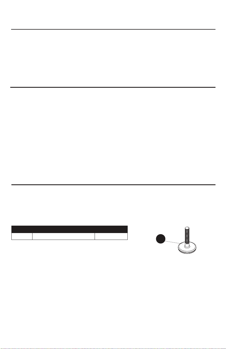
B Leveling Base 2
B
A
PIEZA DESCRIPCIÓN CANTIDAD
A Rampa Para Umbral Ajustable 1
B Base de nivelación 2
CONTENIDO DEL PAQUETE
PIEZA DESCRIPCIÓN CANTIDAD
A Rampa Para Umbral Ajustable 1
B Base de nivelación 2
B
A
SAFETY INFORMATION
HARDWARE CONTENTS (shown actual size)
3
PREPARATION
Please read and understand this entire manual before attempting to assemble, operate or install the
product.
• Ramps are designed for wheelchairs and electric scooters.
• Ramps are rated for a 600 pound capacity; rating is based on double axle, evenly distributed
loads.
• For your safety, a caregiver or aid should be present at all times when using any ramp.
• Proper setup is essential for safe loading and unloading.
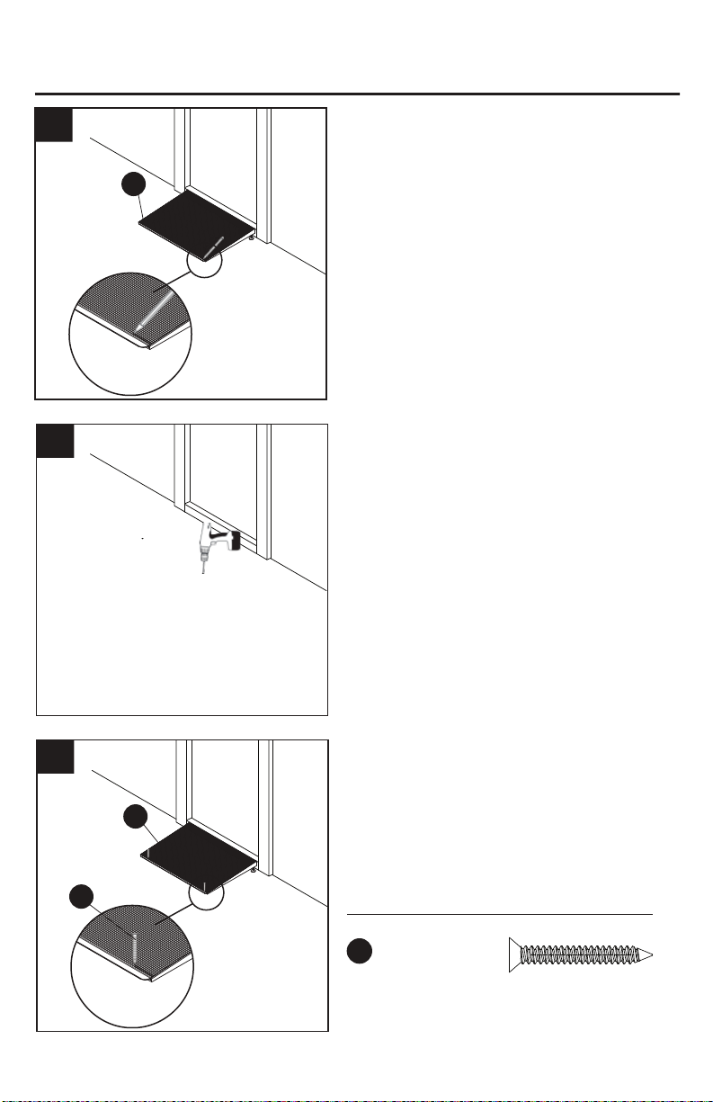
• Make sure that ramp is pressed firmly against the step or platform before using.
• When possible, use the provided flat head pan screws (BB) provided to lock ramp in place.
• Safe lifting practices should be used when lifting product.
• The Americans with Disabilities Act recommends a 1:12 slope; for 2-foot ramp a maximum height
of step/platform not to exceed 2 inches.
• Failure to follow all warnings/instructions may result in ramp slipping off step while occupied.
Hex
Nut
Qty. 2
AA
WARNING
Before beginning assembly of product, make sure all parts are present. Compare parts with package
contents list and hardware contents. If any part is missing or damaged, do not attempt to assemble
the product.
Estimated Assembly Time: 2 minutes
Tools Required for Assembly (not included): None.
Helpful Tools (not included): Drill with 3/16 bit (wood, metal, or masonry depending on what type of
surface you will be drilling pin holes into); Pen/Pencil
BB
Flat Head
Pan Screw
Qty. 2
10
INFORMACIÓN DE SEGURIDAD
ADITAMENTOS (se muestran en tamaño real)
PREPARACIÓN
Lea y comprenda completamente este manual antes de intentar ensamblar, usar o instalar el
producto.
• Las rampas están diseñadas para sillas de ruedas y triciclos eléctricos.
• Las rampas están clasificadas para una capacidad de 272,16 kg; la clasificación está basada en
cargas de doble eje distribuidas uniformemente.
• Para su seguridad, un cuidador debe estar presente en todo momento cuando use cualquier
rampa.
• La configuración adecuada es esencial para una carga y descarga seguras.
• Asegúrese de que la rampa esté presionada firmemente contra el escalón o la plataforma antes
de usar.
• Cuando sea posible, use los tornillos de cabeza plana provistos (BB) para fijar la rampa en su
lugar.
• Se deben usar prácticas de elevación seguras cuando levante el producto.
• La Ley de Estadounidenses con Discapacidades recomienda una inclinación de 1:12; para una
rampa de 0,61 m, la altura máxima del escalón/plataforma no debe exceder los 5,08 cm.
• El incumplimiento de las advertencias/instrucciones podría causar que la rampa se deslice hasta
salirse del escalón mientras se utiliza.
Tuerca
hexagonal
Cant. 2
AA
ADVERTENCIA
Antes de comenzar a ensamblar el producto, asegúrese de tener todas las piezas. Compare las
piezas con la lista del contenido del paquete y la lista de aditamentos. No intente ensamblar el
producto si falta alguna pieza o si éstas están dañadas.
Tiempo estimado de instalación: 2 minutos
Herramientas necesarias para el ensamblaje (no se incluyen): Ninguna.
Herramientas útiles (no se incluyen): Taladro con broca de 3/16" (para madera, metal o mampostería
dependiendo del tipo de superficie en la que perforará los orificios), bolígrafo/ lápiz
BB
Tornillo de
cabeza plana
Cant. 2
SAFETY INFORMATION
HARDWARE CONTENTS (shown actual size)
3
PREPARATION
Please read and understand this entire manual before attempting to assemble, operate or install the
product.
• Ramps are designed for wheelchairs and electric scooters.
• Ramps are rated for a 600 pound capacity; rating is based on double axle, evenly distributed
loads.
• For your safety, a caregiver or aid should be present at all times when using any ramp.
• Proper setup is essential for safe loading and unloading.
• Make sure that ramp is pressed firmly against the step or platform before using.
• When possible, use the provided flat head pan screws (BB) provided to lock ramp in place.
• Safe lifting practices should be used when lifting product.
• The Americans with Disabilities Act recommends a 1:12 slope; for 2-foot ramp a maximum height
of step/platform not to exceed 2 inches.
• Failure to follow all warnings/instructions may result in ramp slipping off step while occupied.
Hex
Nut
Qty. 2
AA
WARNING
Before beginning assembly of product, make sure all parts are present. Compare parts with package
contents list and hardware contents. If any part is missing or damaged, do not attempt to assemble
the product.
Estimated Assembly Time: 2 minutes
Tools Required for Assembly (not included): None.
Helpful Tools (not included): Drill with 3/16 bit (wood, metal, or masonry depending on what type of
surface you will be drilling pin holes into); Pen/Pencil
BB
Flat Head
Pan Screw
Qty. 2
SAFETY INFORMATION
HARDWARE CONTENTS (shown actual size)
3
PREPARATION
Please read and understand this entire manual before attempting to assemble, operate or install the
product.
• Ramps are designed for wheelchairs and electric scooters.
• Ramps are rated for a 600 pound capacity; rating is based on double axle, evenly distributed
loads.
• For your safety, a caregiver or aid should be present at all times when using any ramp.
• Proper setup is essential for safe loading and unloading.
• Make sure that ramp is pressed firmly against the step or platform before using.
• When possible, use the provided flat head pan screws (BB) provided to lock ramp in place.
• Safe lifting practices should be used when lifting product.
• The Americans with Disabilities Act recommends a 1:12 slope; for 2-foot ramp a maximum height
of step/platform not to exceed 2 inches.
• Failure to follow all warnings/instructions may result in ramp slipping off step while occupied.
Hex
Nut
Qty. 2
AA
WARNING
Before beginning assembly of product, make sure all parts are present. Compare parts with package
contents list and hardware contents. If any part is missing or damaged, do not attempt to assemble
the product.
Estimated Assembly Time: 2 minutes
Tools Required for Assembly (not included): None.
Helpful Tools (not included): Drill with 3/16 bit (wood, metal, or masonry depending on what type of
surface you will be drilling pin holes into); Pen/Pencil
BB
10
INFORMACIÓN DE SEGURIDAD
ADITAMENTOS (se muestran en tamaño real)
PREPARACIÓN
Lea y comprenda completamente este manual antes de intentar ensamblar, usar o instalar el
producto.
• Las rampas están diseñadas para sillas de ruedas y triciclos eléctricos.
• Las rampas están clasificadas para una capacidad de 272,16 kg; la clasificación está basada en
cargas de doble eje distribuidas uniformemente.
• Para su seguridad, un cuidador debe estar presente en todo momento cuando use cualquier
rampa.
• La configuración adecuada es esencial para una carga y descarga seguras.
• Asegúrese de que la rampa esté presionada firmemente contra el escalón o la plataforma antes
de usar.
• Cuando sea posible, use los tornillos de cabeza plana provistos (BB) para fijar la rampa en su
lugar.
• Se deben usar prácticas de elevación seguras cuando levante el producto.
• La Ley de Estadounidenses con Discapacidades recomienda una inclinación de 1:12; para una
rampa de 0,61 m, la altura máxima del escalón/plataforma no debe exceder los 5,08 cm.
• El incumplimiento de las advertencias/instrucciones podría causar que la rampa se deslice hasta
salirse del escalón mientras se utiliza.
Tuerca
hexagonal
Cant. 2
AA
ADVERTENCIA
Antes de comenzar a ensamblar el producto, asegúrese de tener todas las piezas. Compare las
piezas con la lista del contenido del paquete y la lista de aditamentos. No intente ensamblar el
producto si falta alguna pieza o si éstas están dañadas.
Tiempo estimado de instalación: 2 minutos
Herramientas necesarias para el ensamblaje (no se incluyen): Ninguna.
Herramientas útiles (no se incluyen): Taladro con broca de 3/16" (para madera, metal o mampostería
dependiendo del tipo de superficie en la que perforará los orificios), bolígrafo/ lápiz
BB
Tornillo de
cabeza plana
Cant. 2