PVR EU 160 Manual

EU 160
Lubricated vane
vacuum pump
Operating and maintenance
instructions
Publication Number:
LI 2333.03 January 2020
EN
TRANSLATION

Operating and maintenance instructions
EN
2
LI 2333.03
Index
1. General information ..............................................................................................page 3
2. Product specifications ....................................................................................... page 4
2.1 Pump description............................................................................................. page 4
2.2 Expected use.....................................................................................................page 5
2.3 Forbidden use....................................................................................................page 5
2.4 Protections........................................................................................................page 5
2.5 Accessories .......................................................................................................page 5
3. Safety rules ........................................................................................................... page 6
4. Transport/handling ............................................................................................ page 8
4.1 Lifting ................................................................................................................ page 8
4.2 Unpacking and components control.............................................................. page 8
4.3 Storage ............................................................................................................. page 8
5. Installation and operation .................................................................................. page 9
5.1 Assembly........................................................................................................... page 9
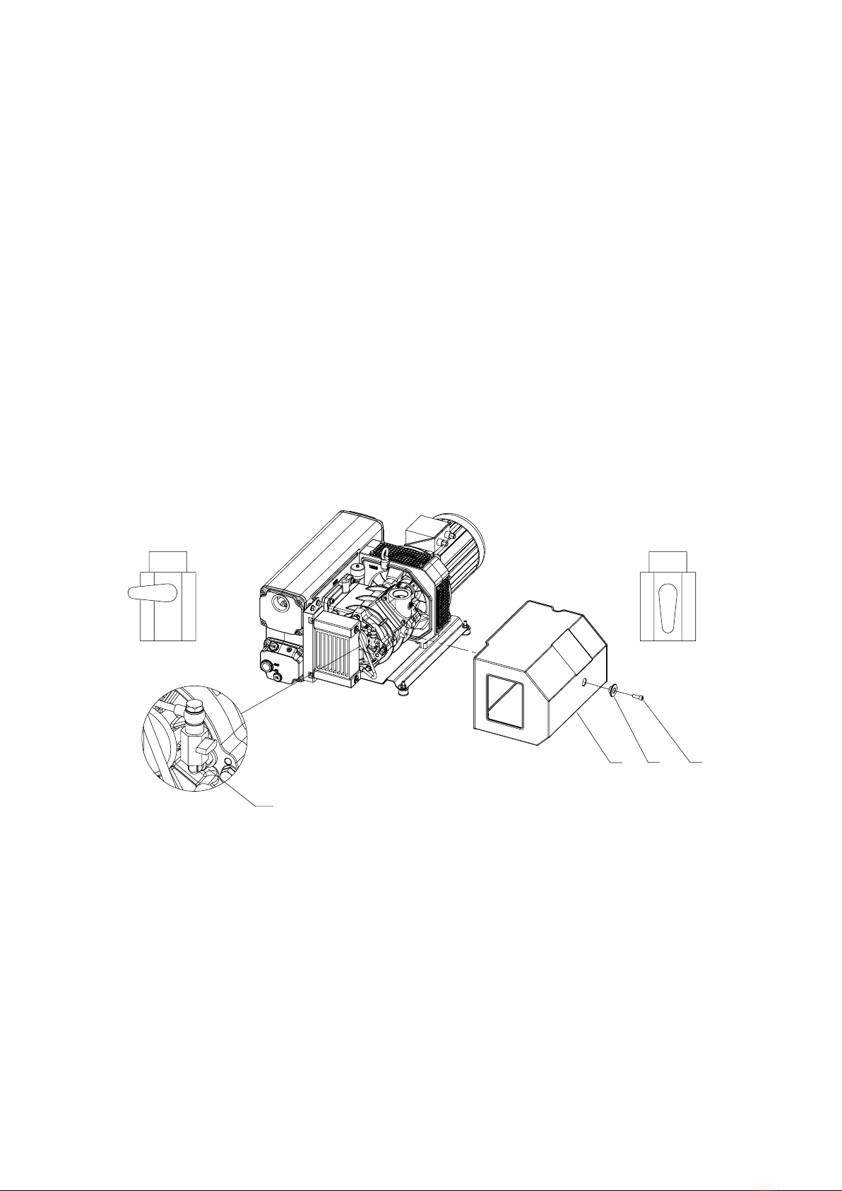
5.2 Operating vacuum range changing ..............................................................page 10
5.3 Location ........................................................................................................... page 11
5.4 Connection to the machine............................................................................page 12
5.5 Discharge air pipe line installation ................................................................ page 12
5.6 Electrical connection......................................................................................page 13
5.7 Commissioning ...............................................................................................page 14
5.8 Tips for using................................................................................................... page 14
5.9 Water vapour intake........................................................................................page 15
6. Servicing...............................................................................................................page 15
6.1 General information ........................................................................................page 15
6.2 Oil change........................................................................................................page 16
6.3 Coupling elastic element replacement ......................................................... page 17
6.4 Exhaust filters replacement ...........................................................................page 18
6.5 Spares necessary for normal servicing.........................................................page 18
6.6 Pump overhaul ................................................................................................page 18
6.7 How to order spare parts................................................................................page 18
7. Lubricants.............................................................................................................page 19
8. Decommissioning................................................................................................page 19
9. Return for repair..................................................................................................page 19
10. Disposal.............................................................................................................. page 20
11. Troubleshooting ................................................................................................. page 21
Attachments
Technical data sheet, exploded view and parts list (RDT)
EC declaration of conformity (DC)
Electric motor operating instructions
Instructions for the accessories

Operating and maintenance instructions
EN
3
LI 2333.03
1. General information
This manual contains information necessary for the proper operation of the pump in
order to prevent unsuitable use and for the safety of the operators. Do not attempt any
other type of operation without having first contacted our Service Department. The
information provided herewith does not intend to replace, integrate or change any rules,
regulations, law by decree, directive or law of specific character in force in the Country
where the installation takes place.
The suggestions given to the sta engaged in the installation and servicing assumes
that the personnel is expert and prepared in facing any problem of servicing, both
mechanical and electrical. For any questions or information not included in this manual,
please contact our Service Department,always providing: model (Model),serial number
(Serial), year of manufacture, stated on the pump name plate.
Symbols used:
WARNING:
Instructions that, if not followed, ELECTRIC SAFETY
could result in serious
personal injuries.
FIRE HAZARD
NOTE:
Instructions that, if not followed,
could result in pump damages. READ THE OPERATING
INSTRUCTIONS
HOT SURFACES
INLET PORT
HARMFUL SUBSTANCES
EMISSIONS EXHAUST PORT
DO NOT DISPOSE INTO
THE ENVIRONMENT DISPOSAL

Operating and maintenance instructions
EN
4
LI 2333.03
2. Product specifications
2.1 Pump description
EU 160 pumps are single-stage, rotary vane lubricated vacuum pumps, with oil
recirculation.
The flanged electric motor is coupled by means of an elastic coupling.
Cooling is achieved by means of an air/oil cooler and a centrifugal fan.
At the pump inlet there is a mesh filter in order to protect it from solid parts having
diameter larger than 1.5 mm.
Furthermore, an integrated non-return valve prevents the oil coming back and the return
of air in the chamber to be pumped down during the stop phase.
In the tank there is a system of oil smokes separation from the discharged air (maximum
residual 2PPM/weight corresponding to 2.4 mg/m3).
The separated oil is recovered automatically by the pump.
The gas ballast valve prevent condensation inside the pump when pumping down small
quantity of vapour.

Operating and maintenance instructions
EN
5
LI 2333.03
2.2 Expected use
These vacuum pumps have been designed to handle air and small quantity of water
vapour only. They are suitable to evacuate closed systems or to operate at a constant
vacuum within the following vacuum range:
EU160 from 0.5 to 350 mbar (absolute)
EU160/B from 10 to 850 mbar (absolute)
The ambient temperature and the inlet temperatures must be included between 12°
and 40°C.
In case you get temperatures outside this range, please get in touch with us.
Handling of other types of gas or vapours must be declared in advance to PVR that will
give the conformity to the specific use.
2.3 Forbidden use
WARNING:
The pump MUST NOT handle:
- liquids or solid substances;
- dangerous, explosive or aggressive gases and vapours;
- pure oxygen or air mixtures enriched with oxygen;
It is forbidden to use the discharge of the pump to create even limited pressures.
WARNING:
It is forbidden to install the pump in a potentially explosive environment.
2.4 Protections
The pump must be protected against suction of dust, solids or liquids.
For those applications where such a protection is not ensured, a vacuum gauge must be
installed on the oil tank for a visual check of the exhaust filter clogging.
In order to get an automatic pump stop, a pressure switch set at 0.6 bar can be installed.
Thepumpissuppliedwithoutelectriccontrolpanel.Theelectricmotormustbeprotected
according to the regulations in force.
WARNING:
In case of applications where the pump stop or failure can cause damages to people
or things, safety measures for the system must be adopted.
2.5 Accessories
The following accessories useful for the installation and for the control of the operation
parameters of the pump are available:
- external inlet filter
- connection fittings
- vacuum meters/ vacuum switches
- pressure meters/ pressure switches
- temperature switch
- low oil level switch

Operating and maintenance instructions
EN
6
LI 2333.03
3. Safety rules
WARNING:
Despite of all the precautions adopted when designing the equipment, there are
some risk elements that arise during operation and servicing.
HOT SURFACES
The temperature of the pump surfaces may exceed 80°C.
Install the pump in a protected area accessible only by authorized personnel, to prevent
possible personal injures due to contact with hot surfaces.
The pump can be placed inside other machines by adopting the necessary safeguards.
Before carrying out any maintenance on the pump, be sure the pump is cold.
HARMFUL SUBSTANCES EMISSIONS
The discharged air contains part of traces of oil mist.
Check the compatibility with the environment.
Make sure a correct air change is allowed otherwise convey the pump discharge outside.
A failure or the seals wear can cause an oil leakage.
Avoid the dispersion to the ground and the pollution of other materials. In case that any
air containing dangerous substances must be pumped down (for example, biological
or microbiological agents), make sure to adopt filtering systems before introducing air
in the work environment.
Used discharged oil from the pump must be disposed in accordance with the regulations
in force in the Country of use.
Do not dispose into the environment.
HAZARD CAUSED BY VACUUM
Any contact with parts under vacuum can cause injuries.
Avoid any contact with the pump inlet port during the pump operation. Introduce air in
the inlet circuit before every operation cycle.
HAZARD CAUSED BY PRESSURE
The pump tank is pressurized. Do not open the oil filling and discharge plugs during
operation.
FOR A SAFE MAINTENANCE
All maintenance operations must be carried out with the pump idle, disconnected from
the electrical supply, with the pump cold, vented to atmospheric pressure. Prevent
unexpected start-up (e.g. block the power switch with a personal lock).

Operating and maintenance instructions
EN
7
LI 2333.03
ELECTRIC SAFETY
Some components of the electric equipment are electrically charged during operation.
Any contact may cause serious injuries to persons or objects.
Connection and control of the electric system must be carried out by skilled personnel
only.
The electrical equipment must comply with the EN 60204-1 standard and with any other
law in force in the Country of use.
Besides, electrical equipment must comply with EN 61000-6-4 and EN 61000-6-2
standards concerning electromagnetic compatibility and electromagnetic immunity
for industrial environment.
FIRE HAZARD
WARNING! The use of the pump in situations unforeseen or not recommended by this
manual, as well as lack of correct maintenance, may create high risks for overheating
or fire.
In case of a fire do not use water to extinguish but use a powder CO2extinguisher or
other means compatible with the electrical equipment and lubricating oil.

Operating and maintenance instructions
EN
8
LI 2333.03
4. Transport/handling
4.1 Lifting
The orientation of the packed components must correspond to the instructions given
by the pictograms on the external covering of the packaging.
For unloading use a lifting equipment suitable for the pump weight.
For lifting the packaging and the pump, please refer to the figures here below.
Pump packaged (Figure 1)
Pump with motor (Figure 2).
Pump without motor (Figure 2).
4.2 Unpacking and components control
When receiving the machine, check that the packaging is intact or shows any signs of
damagesoccurredduringtransportation.Ifthereisnodamage,proceedtotheunpacking
and check the machine further. In case of damages are found, inform immediately PVR
and the carrier. A representative will contact you or it may be dispatched to the site to
inspect and file full damage report.
4.3 Storage
Thepumpsmustbe storedor transportedwithoutoilandprotectedfromtheatmospheric
agents at a temperature between -15°C and 70°C (normal humidity rate max. 95% non
condensing).
EU 205
Fig.2
L HB
Packing size 930 mm 410 mm490 mm
Pump Packaged pump
Weight of the pump with motor 50Hz
104 Kg
110 Kg
75 Kg
114 Kg
120 Kg
85 Kg
Weight of the pump with motor 60Hz
Weight of the pump without motor
Fig.1
L
B
H

Operating and maintenance instructions
EN
9
LI 2333.03
5. Installation and operation
5.1 Assembly
If the pump is supplied without any electric motor, install a motor whose characteristics
are the same as stated on the technical sheet, constructive form IM B 5.
WARNING:
- Use lifting equipment suitable for the motor weight (between 29 and 35 Kg
depending on the versions)
- To assure the continuity of the equipotential circuit of the pump, clean the contact
surfaces very well, by removing any grease or protective painting.
NOTE:
After the assembly, check that the distance between the two coupling halves is
20 ±1.5 mm (Figure 4)
Remove inlet and exhaust plastic caps.
Fit the external filter in horizontal position to prevent dirt coming inside the pump
during the cleaning of the cartridge. (Figure.5)
Fig.5
Fig.4
20
+1,5
0
A

Operating and maintenance instructions
EN
10
LI 2333.03
5.2 Operating vacuum range changing
Pumps of EU205 - EU300 series are fitted with a manual selector switch for the choi-
ce of the suitable working vacuum range:
· EU from 0.5 to 300 mbar
· EU/B from 10 to 850 mbar
In case the pump working range needs to be changed, please follow the instructions.
Remove the casing (Pos.89) by unscrewing the screws (Pos.52-92) to reach the tap
(Pos.109).
Position the selector switch horizontal for the EU type, position it vertical for the
EU/B one. The predetermined vacuum range is the one stated on the pump name
plate.
89 92 52
EU
EU/B
109

Operating and maintenance instructions
EN
11
LI 2333.03
5.3 Location
WARNING:
The pump must be installed in a protected area (see safety rules).
It must be fastened with support feet on horizontal surface.
It must be accessible for correct and easy maintenance, by respecting the minimum
distances from possible obstructions (see figure 6).
It must be accessible to suitable lifting equipment.
NOTE:
Ensure the air exchange in the room or inside the machine where the pump has been
installed.
To assure a sucient cooling, avoid exceeding 40°C of ambient temperature.
The pump must be protected against jets or sprays of water that may penetrate the
tank through the exhaust port.
Whenever the pump is installed outside, it must be protected against atmospheric
agents and it must be used with an oil suitable for low temperature.
Avoid warm air coming from the exhaust or the cooling fans causing discomfort to the
personnel.
Do not install the pump in a dusty area or where other materials may block or cover
the cooling surfaces quickly.
A CB D
300 mm 100 mm90 mm 304 mm
Fig.6
A
B
CD

Operating and maintenance instructions
EN
12
LI 2333.03
5.4 Connection to the machine
The connection to the chamber to be pumped down must be carried out by means of
pipes of the same diameter as the inlet port.
Pipe weights and expansions, if any, must not rest on the pump.
It is advisable to make the final connection to the pump inlet port with flexible pipes or
fittings.
It is important that all the pipes and the dierent fittings are tight.
Very long or small diameter pipes decrease the pump performances.
This symbol identifies the inlet port.
For further information, please refer to the RDT attached herewith.
5.5 Discharge air pipe line installation
If the pump has been installed in a room with poor air exchange, it is possible to pipe
the pump discharge air to other rooms or outside.
Use pipes with the same diameter as the tank discharge port with a maximum length
of 15 m.
For longer pipes increase pipe diameter. Pipe weights must not rest on the pump.
In the final length use flexible pipes or pipe fittings.
NOTE:
this pipe must be descending, to avoid the condensate going back to the tank.
WARNING:
do not connect ball valves to this pipeline.
This symbol identifies the exhaust port.
For further information, please refer to the RDT attached herewith.

Operating and maintenance instructions
EN
13
LI 2333.03
5.6 Electrical connection
The control panel and electrical connections must be carried out by skilled personnel
and conform to the EN 60204-1 rules or to other local regulations in the Country of use.
The electrical equipment must comply with EN 61000-6-4 and EN 61000-6-2 standards
concerning electromagneticcompatibility,emissionstandardandimmunityforindustrial
environment.
Check the main voltage and frequency in use to correspond to the data stamped on the
motor name plate.
The electric motor must be protected against overload.The full load amperage value on
the motor name plate must be considered when sizing the electrical components and
motor protection against overloading.
Make sure the grounding is correctly done.
Carry out the electric connectionfollowingthediagramshownonthemotorterminalbox.
Check direction of rotation by starting the pump for a short time (2-3 seconds). The
correct direction is shown by the arrow on the pump (figure 7).In case of wrong rotation,
it is necessary to change the motor rotation by exchanging position of two of the three
connections previously connected to the motor terminal box.
Fig.7

Operating and maintenance instructions
EN
14
LI 2333.03
5.7 Commissioning
The pump is supplied without lubricating oil.
NOTE:
the operation without oil causes big damages to the pump.
Carry out the first filling up through the plug (E) up to the half of the sight glass (F) and
close the plug (E) (Figure 8).
Start the pump and take it to the maximum vacuum level for at least 2 minutes.
Stop the pump, check again the oil level and add the lacking oil, if necessary, in
order to get the correct oil level.
NOTE:
a quantity of oil greater than necessary may clog the oil separator and damage
the pump or the electric motor.
5.8 Tips for using
When the room temperature is lower than 10°C, it is a good practice to let the pump
operate at the ultimate pressure (Inlet port closed, without load) for about 15 minutes.
During this period the pump may not reach the stated pressure limits.
NOTE:
Avoid operating the pump for long periods with inlet port vented to atmospheric
pressure.
Avoid frequent stop-starting, as this will lead to premature wear of the coupling
elastic element.
It is recommended not to exceed 10 starting/hour. For more frequent starting, it
is recommended to install a soft starter device.
Fig.8
EE
FF
GG

Operating and maintenance instructions
EN
15
LI 2333.03
5.9 Water vapour intake
In order to pump down any water vapour, the following operations are recommended:
Let the pump run for thirty minutes at the maximum vacuum in order to bring the pump
temperature to its operating value.
At the end of the working cycle, in case of further presence of condensate in the oil, let
the pump run for at least thirty minutes at the maximum vacuum.
It is advisable to carry out this operation before stopping the pump for a long time. The
gas ballast valve will allow the elimination of water condensate from the lubricating oil.
6. Servicing
A
K
D
D1
D2
C
B
B7
B6
B5
B4
B3
B2
B1
Fig.9

Operating and maintenance instructions
EN
16
LI 2333.03
6.1 General information
In order to keep the pump operating at a high eciency level, it is mandatory to follow
all periodical service points listed in the table below.However, more frequent service
operations may be necessary depending on what the pump is used for (suction of con-
densable vapours, suction of powders or polluting substances).
For such cases,only directexperiencecanindicatethecorrect service frequencyneeded.
The exhausted oil and the replaced spare parts must be considered as special waste
products and handled according to the local regulations in the Country of use.
WARNING:
Before every maintenance operation:
Always ensure that the pump is insulated from the electrical network so that it
can’t start automatically.
Wait until the pump gets cool and make sure it has reached a non-dangerous
temperature.
Introduce air in the inlet circuit.
SERVICING FREQUENCY DESCRIPTION OF THE OPERATION
AUTHORIZED PERSONNEL
24
Hours/every day
Check oil level before starting. Operator
100
Hours/every week
Clean the external inlet element with a blast of air (Figure 9
pos.A). Operator
Clean the cooling surfaces of the pump, of the oil cooler and of
the electric motor with a blast of air. Operator
500/1000*
Hours/every 6
months
Change the lubricating oil (Figure 9 pos. C). Skilled Worker
Ifthepressuregaugeisfittedtothepump,checktheoilseparator
(max 0,6 bar), if necessary, replace it. Skilled Worker
Replace the gas-ballast felt disk (Figure 9 pos. K). Skilled Worker
2000
Hours/every year
Replace the exhaust filters (Figure 8 pos.B). Skilled Worker
Check and if necessary replace the coupling elastic insert
(Figure 9 pos. D). Skilled Worker
Check the electrical connections. Skilled Worker
Check functionality of the float valve and clean it. Skilled Worker
8000
Hours/every 2 years
Grease electric motor bearings (if there is the grease slinger).
Pleaserefertotheelectricmotornameplateand/or motormanual.
Skilled Worker
30000
Hours/every 5 years
Pump overhaul. Customer Service
* The first oil change has to be done after 500 hours of operation. If any polluting substances are found in the oil, next oil
change could take place within 1000 hours.

Operating and maintenance instructions
EN
17
LI 2333.03
6.2 Oil change
For a correct operation, oil change should be performed when the pump is still warm.
WARNING:
Use protective gloves to avoid injury caused by heat.
Please refer to Figure 8, section 5.6.Unscrew the oil filling plug (E) and the discharge
plug (G) only after having placed underneath the pump tank a suitable container (proper
size and shape) for collecting the total quantity of oil.
Once the oil in tank has completely been discharged from the tank, reassemble both
plugs (“E” and “G”) and let the pump run under vacuum for about one minute, so that
the lubricating/cooling line gets emptied and any oil residual keeps inside the pump.
Then remove the plugs and discharge the rest of the oil.
If the oil is polluted or if some water is in the oil, clean the pump by letting it run with a
suitable quantity of oil (up to the minimum level shown on the tank) at maximum vacuum
level for at least 5 minutes.
Drain the oil again.
Replace the oil filter Figure 9 (pos. C) and follow up to fill with fresh oil (please see“com-
missioning” and “recommended oil table”).
6.3 Coupling elastic element replacement
Please refer to Figure 9.
Removethemotorassembly(pos.D1) unscrewingthescrews (pos.D2).Checktheelastic
element (pos.D) conditions.If necessary, replace it. Reassemble by means of the screws.
WARNING:
please use suitable lifting equipment.
Weight expected for the electric motor between 29 and 35 Kg
depending on the versions.
NOTE:
the operation with damaged elastic element causes an anomalous pump noise,
especially when starting the pump and may lead to coupling and pump shaft failure.

Operating and maintenance instructions
EN
18
LI 2333.03
6.4 Exhaust filters replacement
Very dirty exhaust filters may cause a considerable pump temperature increase and in
extreme cases oil lubricant spontaneous ignition.
Maximum allowed pressure in the tank is 0,6 bar measured at the maximum capacity
(when the pump is working with the inlet open to atmospheric pressure).
If a pressure gauge has been fitted to the tank, check the exhaust filter blockage with
the pump warm.
To replace the filter, remove the cover (pos. B2) by unscrewing its screws (pos. B1).
Unscrew the screw (pos. B4), remove the washers (pos. B5-B6) and then the fixing
cartridge disk (pos. B7).
Replace all the exhaust filters (pos.B) and their O Rings (pos. B8). Reassemble the fixing
cartridge disk, the washers and tighten the screws.
Reassemble the discharge cover. If necessary, replace the gasket (pos. B3).
6.5 Spares necessary for the normal servicing
The recommended spares are shown in the list of the exploded drawing marked with
the letter “R” (see RDT). They are contained in the minor spare parts kit.
6.6 Pump overhaul
For this operation please request the proper instructions and direct any questions to
our Customer Service department. The overhaul consists of a complete disassembly,
cleaning of all components as well as replacement of parts that are subject to wear
(pump and motor bearings, vanes and gaskets).
6.7 How to order spare parts
When ordering spare parts,always state the pump model,serial number, year of produc-
tion, electric motor characteristics (manufacturer’s name, model, kW, V, Hz), position
reference on the spare parts list, description and quantity needed.
Dierent types of maintenance kits are available (ref. RDT attachment).

Operating and maintenance instructions
EN
19
LI 2333.03
7. Lubricants
Oil recommended for generic use
Mineral oil for compressors according to DIN 51506 group VC-VCL or VDL classifica-
tion ISO L-DAG.
Ambient temperature Viscosity PVR oil
12 - 40°C ISO 100 Rotant VF 204
5 - 30°C ISO 68 Rotant VF 203
Oil recommended for heavy duty, both for high and low temperatures.
Synthetic oil on PAO basis (polyalphaolefins).
Ambient temperature Viscosity PVR oil
5 - 40°C ISO 100 Rotant VF 304
0 - 30°C ISO 68 Rotant VF 303
Oil recommended for application in the food industry.
Synthetic oil lubricant compatible for chance contact with food complying with NSF
H1 specifications.
Ambient temperature Viscosity PVR oil
5 - 40°C ISO 100 Rotant VF 404 H1
0 - 30°C ISO 68 Rotant VF 403 H1
For ambient temperature outside the stated range, please get in touch with our Custo-
mer Service Department.
8. Decommissioning
Drain the oil from the pump prior to the removal.
If the oil is polluted, flush the pump with fresh oil (see “oil change”).
Drain the oil from the tank, plug the inlet and the discharge ports and store the pump
without oil.
9. Return for repair
In case of pump return for repair to PVR, provide a list of substances which have come
in contact with the pump and advise the risks involved in handling, if any. Drain the
lubricant from the pump prior to shipping the pump back.

Operating and maintenance instructions
EN
20
LI 2333.03
10. Disposal
Meaning of the “WEEE” logo found in labels
The following symbol is applied in accordance with the EC WEEE (Waste Electrical and
Electronic Equipment) Directive.
This symbol (valid only in countries of the European Community) indicates that the
product it applies to must NOT be disposed of together with ordinary domestic or
industrial waste but must be sent to a dierentiated waste collection system.
The end user is therefore invited to contact the supplier of the device, whether the
Parent Company or a retailer, to initiate the collection and disposal process after
checking the contractual terms and conditions of sale.
Table of contents
Other PVR Water Pump manuals
Popular Water Pump manuals by other brands

SMC Networks
SMC Networks PAF3413 Operation manual

Pratissoli
Pratissoli LK-LKN Use and maintenance manual

Graco
Graco saniforce 2150 Operation

MDM
MDM C-Shell 4X3 Installation and service manual

Haskel
Haskel AAD-5 Operating and maintenance instructions

Ingersoll-Rand
Ingersoll-Rand 650949-X Operator's manual