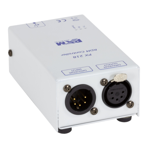
PXM PX218 User manual

MANUAL
RDM
Controller
R
PX218

TABLE OF CONTENTS
1. General description...................................................................................
2. Safety conditions.......................................................................................
3. Description................................................................................................
4. Software installation..................................................................................
5. Controller software....................................................................................
5.1. Connection between the controller and PC...............................
5.1.1. Searching for connected devices..............................
5.2. General overview.......................................................................
5.2.1. DMX patch grid..........................................................
5.2.2. Sensors.....................................................................
5.2.3. RDM settings.............................................................
5.3. Modification of device times......................................................
6. Wiring diagram..........................................................................................
7. Technical specification...............................................................................
8. Technical drawing......................................................................................
Declaration of conformity...............................................................................
3
3
4
5
6
6
7
8
9
11
12
13
14
15
15
16
The manufacturer reserves the right to change the operation and handling of the device
in order to improve the product.
tel.: (12) 626 46 92
fax: (12) 626 46 94
E-mail: [email protected]
Internet: www.pxm.pl
Ver.1.0.
2
PXM Marek Żupnik spółka komandytowa
Podłęże 654
32-003 Podłęże

1. GENERAL DESCRIPTION
2. SAFETY CONDITIONS
Controller PX218 RDM Controller is a device powered directly from the USB port with safe
voltage 5V, however, during its installation and use the following rules must be strictly observed:
1. The user mustn't connect any external power supply unit to the device. The power delivered
through the USB port while the device is connected to a PC is enough for its proper work.
2. All the conductors should be protected against mechanical and thermal damage.
3. In case of damage to a conductor, it should be replaced with a conductor of the same technical
parameters.
4. Connection of DMX signal can be made with a shielded conductor only.
5. All repairs, connecting and disconnecting of cables can only be made with cut off power
supply.
6. The device should be strictly protected against contact with water and other liquids.
7. All sudden shocks, particularly dropping, should be avoided.
8. The device cannot be turned on in places with humidity exceeding 90%.
9. The device cannot be used in places with temperature lower than +2°C or higher than +40°C.
10. Clean with damp cloth only.
PX218 - RDM Controller is a multifunction device which allows for changing parameter settings of
products connected to complex installations using the DMX-512 protocol.
PX218 communicates with other products through the RDM (Remote Device Management)
protocol which is a kind of extended DMX512 protocol. The DMX protocol has been designed to
enable one-direction flow of data, while its extension, the RDM protocol, can send information in
two directions. For this reason, it is possible to simultaneously receive and send information, and
hence to monitor the operation of the devices compliant with the RDM protocol, and reconfigure
their operating parameters.
Input and output in DMX-512 standard are used to connect to DMX network.
PX218 operation management is done using the applications on the Windows platform via USB
2.0 port. The device can be supplied only via a cable connected to the USB port of the computer.
3

4
3. DESCRIPTION
PUSH
21
3
4
2 1
Designations:
1. DMX input connector (3-pin XLR female slot)
2. DMX output connector (3-pin XLR female slot)
3. Information diodes:
Power: power connection - orange diode
Tx: transferring data through PX218 - blue diode
Rx: receiving data through PX218 - green diode
4. miniUSB interface (miniUSB type B)

4. SOFTWARE INSTALLATION
The software can be installed on Windows . The
®® ®
XP, VISTA™, Windows 7 or Windows 8
procedure for installing the software varies depending on the operating system on the computer.
Windows 7 system is an example here.
®
Installation is as follows:
1. From the drop-down menu, select the language for the installation and confirm by clicking
[OK].
The installation file is attached to the driver on a CD, or available for download from the
http://pxm.pl
2. Carefully read the license agreement; if you agree to the terms of this agreement, click
[I Agree] to continue the installation.
3. Select the components you want to install, then click [Next].
4. Select the folder in which you want to install the software. Confirm your selection by clicking
[Next].
5. Select the start menu in which you want to create a shortcut to the program. You can also
rename the folder, then click [Install].
6. To enable the correct installation of all selected software components, you need to install the
USB driver. The [Device driver installation wizard] will be displayed in another window, click
[Next] to continue.
7. The wizard displays the message "The drivers are successfully installed on this computer",
click [Finish].
8. The PX218 installer has successfully installed the software, click [Close].
9. Open the installed PX218 program.
5

Program designed to manage the PX218 controller via a PC allows you to easily program devices
supported by the RDM (Remote Device Management) protocol. It allows, among other things, for
changing the address of DMX channels and values on the DMX channel. The program reads
information from sensors installed in various devices without the need to connect to each of them
separately. Connection between the controller and PC is done via USB. The application is
available in three language versions – Polish, English, and German. Other language versions
can be supplied on request. The software can be run on PCs.
After installing the software, run the application, and then connect the controller to PC with the
USB cable. During the first connection, a standard installation procedure is performed on the new
device. In such case, indicate the location of the controller displayed at the end of the software
installation Px218_PXM_RDM_Controller_P_1_6.exe. The connection is established after
selecting the available PX218 from the drop down menu [Devices] in the top left corner of the
window. Then, the program displays the “Connected” status, catalogue number of the device,
serial number and firmware version.
5. CONTROLLER SOFTWARE
5.1. Connection between the controller and PC
6

7
The whole column on the right-hand side of the window, under the “Connected” or
“Disconnected” message, is responsible for searching for and selecting the currently
programmed device equipped with the RDM receiver and thus communicating with the PX218.
On the left, there is displayed information on the currently selected device (highlighted in blue in
the right-hand column). Additionally, through other tabs ([DMX Patch Grid], [Sensors], [RDM
Settings]), the user can receive information on the device or change some parameters.
Once the program "PXM RDM Controller” is connected with PX218, it is possible to start
searching for all devices connected to the DMX line. To do this, select [Full Discovery] located in
the top left corner of the window. After searching and receiving the response from devices
connected to the DMX line, the program displays the products found on the right in the [Devices]
frame.
Using the pop-up keys next to [SORT BY] and [ORDER], it is possible to sort and change the
display of the list of the devices found.
5.1.1. Searching for connected devices

5.2. General overview
Section [DMX 512] contains the following:
ź Footprint: number of channels assigned to a device operating in the selected mode
ź Current Personality: selected operating mode of the device
8
[Supported parameters] contains:
ź Parameter count
ź Parameters
Settings which can be edited in this tab are [Device Label] and [Start Address]. Check boxes
are highlighted in white. [Device Label] is a parameter which allows you to describe the product
as needed. On the other hand, [Start Address] enables the determination of the first DMX
address (and automatically the next addresses) for the device.
After setting or changing the parameter before leaving the [Device Overview] tab, save changes
to let the end device remember them.
The first tab [Device Overview], available for each device found, contains information on the
detected product. The displayed messages are divided into sections: [Description], [DMX 512],
and [Supported Parameters].
[Description] contains the following information:
ź RDM Protocol Version
ź Device Model ID
ź Product Category
ź Software Version ID: version of the connected device firmware
ź Sub Device Count
ź Device Label: editable parameter which allows for describing the device
ź Manufacturer Label

The [DMX Patch Grid] tab allows for viewing the DMX channels currently assigned to devices
connected to the DMX-512 line and with built-in option to support the RDM protocol. Channels
which are assigned to the devices or slave devices are highlighted in green (one single cell is one
channel). Grids (channels) assigned to the selected device in the [Devices] column in the bottom
right-hand corner of the window are highlighted in light green. Red colour informs that two
devices are assigned to the same DMX address or, optionally, channels sent by the device are out
of range (above 512) of the DMX-512 protocol.
9
5.2.1. DMX patch grid
Additionally, the [Identify] box located under the [Save changes] button allows for activating the
option of physical indication of the device among other devices connected to the system (in the
case of PXM lamps, this will include blinking of diodes indicating the identified product).

The [DMX Control] button is located above the field displaying the cells with subsequent
channels and allows for changing the DMX value for each channel in real time. Unfortunately, it is
not possible to save the set DMX values. This function is used only to configure scenes from PC.
Once this button is selected, PXM RDM Controller opens another window and displays the [Grid]
tab by default. This allows you to set the DMX value.
Values of the DMX channels can be changed in several different ways:
!by selecting the desired cell and entering the DMX value using the keyboard
!by selecting the desired cell and double-clicking the left mouse button
!and then, using the cursors (on the screen or keyboard), entering the desired DMX value;
!by selecting the desired cell or the group of cells and clicking the right mouse button; the
slider appears and it can be used to set the desired DMX value (this option enables the
change of the values of selected channels at the same time)
!by selecting one cell, and copying its value, e.g. using the Ctrl+C or Ctrl+V keyboard
shortcuts
10

11
The next tab – [Sensors] – is used to check parameters of sensors installed in the device. These
may be, for example, temperature sensors. In addition to the current temperature, the program
displays information on the lowest and the highest recorded temperature. What is more, it
displays messages relating to the operation time of the product, such as: number of hours,
number of power cycles, and – for lamps – e.g. number of flashes.
Parameters relating to the lamps (at the very bottom of the window), i.e. [Hours] refer to the total
number of hours of lamp operation (time when it was on). Another parameter [Strikes] informs
about the number of lamp activations.
The last value [State] signals the following situations:
!LAMP_OFF - lamp is off
!LAMP_ON - lamp is on
!LAMP_STRIKE - activation of discharge lamps (applies to discharge lamps)
!LAMP_STAND BY - reduced lamp power, standby mode
!LAMP_NOT_PRESENT - lamp is not connected
!LAMP_ERROR - lamp communication error
5.2.2. Sensors
The [Sliders] tab allows you to change the values of the pre-selected devices or slave devices
visible in the menu in the bottom right-hand corner of the main program window.

The following typical options (highlighted in black) can be checked:
źSupported parameters - a list of parameter identifiers supported by the device
źParameter description - description of individual parameters
źDevice info - information on the device
źSoftware version label - information on the device firmware
źIdentify device - status of device identification option (on-off)
Additional options (highlighted in blue) are selected by the manufacturer of the device connected
to the DMX line, e.g. lamp.
These are parameters adjusted to the capabilities of the device, and a description of their
functions should be available in the instruction manual of this product.
12
5.2.3. RDM settings
The last tab [RDM settings] contains information on all of the RDM parameters provided by the
RDM protocol to the device. In addition to viewing the messages, it is also possible to set new
values for the options which allow for such a change.
Available parameters are displayed on the right-hand side of the window [PID - GET/SET]. The
[RDM GET] key allows you to read their current values, and the [RDM SET] is used to enter the
new settings. Once the [RDM SET] key is selected, a new window pops up which is used to select
and save settings depending on the option.
Description of colours: black – standard options (RDM); blue – additional optional parameters
supported by the product.

13
5.3. Modification of device times
The [Timeout] menu in the top left corner of the main program window makes it possible to
change the communication settings through various interfaces supported by PX218, i.e. [RDM
timeout], [USB timeout], [DMX timeout].
Apart from manual modification of settings, it is also possible to change them automatically.
The [Default] key restores the default settings stored in the device, while the [Strict] key changes
settings to the minimum standard settings. We generally recommend using the default settings;
in the event of communication problems, try the strict settings, and then, if the problem persists,
manually modify individual parameters.

14
PC
Lamp supporting the RDM protocol, e.g. PX256
Connection of the DMX cable from the lamp with the XLR connector
The drawing below presents the description of XLR pins:
SHIELD
DMX+
DMX-
NOTE: Under no circumstances can the cable shield be connected to the device grounding.
6. WIRING DIAGRAM
1
2
3
PUSH
Example of connecting the DMX cable from the lamp to the cable with XLR connector
1 - black wire - shield
2 - white wire - DMX -
3 - red wire - DMX +
2
1*
3

15
8. TECHNICAL DRAWING
41
PUSH
108
102
37
39
61
7. TECHNICAL SPECIFICATION
- available connectors:
- communication with PC:
- power supply:
- weight:
- dimensions:
- length
- width
- height
USB, 3-pin XLR slot/plug
YES (USB Mini-B interface)
5V DC (directly from the USB port)
0,25 kg
108 mm
61 mm
41 mm

DECLARATION OF CONFORMITY
according to guide line 2004/108/WE
16
tel: 12 626 46 92
fax: 12 626 46 94
e-mail: [email protected]
http://www.pxm.pl
ul. Przemysłowa 12
30-701 Kraków
SYSTEMY OŚWIETLENIA MUZEALNEGO STEROWNIKI dmx LAMPY LED Oświetlenie ARCHITEKTONICZNE Cyfrowe ściemniacze mocy
PXM Marek Żupnik sp. k.
ul. Przemysłowa 12
30-701 Kraków
RDM Controller
PX218
PN-EN 55103-1:2012
PN-EN 55103-2:2012
DMX signal has to be connected by using a shielded
cable, connected to the GND pin.
mgr inż. Marek Żupnik.
Name of producer:
Manufacturer’s address:
We declare that our product:
Product name:
Product code:
complies with the following standards:
EMC:
Additional information:
Kraków, 26.06.2012
Table of contents
Other PXM Controllers manuals
Popular Controllers manuals by other brands

Resol
Resol DeltaSol BX+ V2 Commissioning manual

Autonics
Autonics SPR1 Series User Manual for Communication

Savant
Savant SmartLighting SSL-P018 Quick reference guide

Allen-Bradley
Allen-Bradley PowerFlex 70 installation instructions

ROBBE
ROBBE RO-Control NAVY Series operating manual

amiad
amiad ADI-P quick guide