PXM PX254 User manual

MANUAL
LED Driver
3 x 6A OC
PX254
R

CONTENTS
3
3
4
4
5
5
6
7
7
9
9
10
11
11
12
13
14
16
17
18
18
19
1. General description.............................................................................................................
2. Safety conditions.................................................................................................................
3. Connections and control elements description...................................................................
4. Designation of displayed messages....................................................................................
5. DMX address settings.........................................................................................................
6. Display flip function
7. MASTER / SLAVE function.................................................................................................
8. White balance.....................................................................................................................
9. Colour settings mode..........................................................................................................
10. Individual settings................................................................................................................
11. No DMX signal response.....................................................................................................
12. Description of programs......................................................................................................
13. Light control frequency........................................................................................................
14. Screen saving (screen blanking).........................................................................................
15. Smooth................................................................................................................................
16. Default settings and memory error (Err)..............................................................................
17. RDM....................................................................................................................................
18. Programming.......................................................................................................................
19. Connections scheme...........................................................................................................
20. Dimensions.........................................................................................................................
21. Technical specification.........................................................................................................
22. Declaration of conformity.....................................................................................................
.............................................................................................................
Manufacturer reserves the right to make modifications in order to improve device operation.
PXM Marek Żupnik spółka komandytowa
ul. Przemysłowa 12
30-701 Kraków, Poland
tel.: +48 12 626 46 92
fax: 626 46 94
E-mail: [email protected]
Internet:
+48 12
www.pxm.pl
Rev 2.0

3
1. GENERAL DESCRIPTION
2. SAFETY CONDITIONS
PX254 LED Driver 3 x 6A OC is a device powered with safe voltage 12-24 V; however, during its
installation and use the following rules must be strictly observed:
1. The device may only be connected to 12 - 24 V DC with current-carrying capacity compatible
with technical data.
2. All the conductors should be protected against mechanical and thermal damage.
3. In the event of damaging any conductor, it should be replaced with a conductor of the same
technical data.
4. Connection of power supply can only be made with a conductor of minimum cross-section area
2
of 2,5mm and DMX signal with shielded conductor.
5. All repairs and connections of outputs or DMX signal can only be made with cut off power
supply.
6. PX254 should be strictly protected against contact with water and other liquids.
7. All sudden shocks, particularly dropping, should be avoided.
8. The device cannot be turned on in places with humidity exceeding 90%.
9. The device cannot be used in places with temperature lower than 2°C or higher than 40°C.
10. Clean with damp duster only.
PX254 driver is designed to control the LEDs. Built-in DMX receiver allows to control 3 DMX
channels (R, G, B) directly with the DMX protocol. Wide range of power supply voltage and high
current carrying capacity outputs (6A) permit a control of large quantities of LEDs. What is more
the PX254 has built-in fuses that can be replaced by the user by himself.
PX254 can be either controlled by DMX, and act independently. In this case, the user is offered a
fully programmable scene and 18 pre-programmed sequences, which can also freely change the
playback speed and fluidity changes in steps. By using 16-bit resolution control of each channel
is completely smooth. In addition, the PX254 driver gained control mode called effect mode to
control the programs built into the driver and the simultaneous change the settings of parameters
such as speed, brightness and fade using DMX-512 signal sent from the external controller.
The driver has a built-in tuning frequency signal system ("flicker free" technology), which makes it
particularly useful in applications for the television industry. The RGB LEDs often differ quite
substantially in parameters, this can cause problems in obtaining a white color (at full power
especially). Therefore PX254 comes with a very useful function called "white balance". Thanks to
it you can choose color correction for each set of LEDs controlled by the device to achieve at full
power the color white. What's more, this feature also allows you to adjust the color temperature of
white color.
The PX254 is produced in common anode version - it allows LEDs connection on common
anode.

3. CONNECTIONS AND CONTROL ELEMENTS DESCRIPTION
4. DESIGNATION OF DISPLAYED MESSAGES
DMX address of a device - a basic item in the MENU
setting parameters for each channel individually
DMX address setting
control method selection (RGB, LIGHTNESS / COLOUR, etc.)
no DMX signal response method selection
MASTER / SLAVE mode settings
LIGHTNESS /COLOUR control mode
RGB control mode
setting parameters for all channels simultaneously
V+
3
2
1
4
5
1
DMX-512 input
2DMX-512 output
3
4Display
5Control outputs
6Programming keys
HSL control mode - HUE / SATURATION / LIGHTNESS
RGB Dimmer control mode
Power supply
6
4
effect control mode
all outputs at 100%
all outputs off
scene

5
number of channels being sent in the MASTER mode
white colour balance setting
red balance
green balance
blue balance
white colour balance on / off
program playback speed
level of steps change smoothness in the program
red during scene programming colour
green colour during scene programming
basic frequency of brightness control
blue colour during scene programming
screen and DMX signal LED blanking
MASTER mode on / off
DMX address settings for first channel
5. DMX ADDRESS SETTING
The menu of the PX282 driver allows for setting the DMX address within a range between 1 and
506-511 depending on work mode of device. For example in RGB mode it occupies three
consecutive DMX addresses. If start address is set to 510, the last channel is occupied by
address 512.
To set the DMX address:
1. Set the Adr function.
2. Use the "next" or "previous" buttons to set the selected DMX address.
1 2
NEXT
ENTER
ENTER
programme no. 17
memory error message
restore default device settings menu

standard
position
upside-down
position
7. MASTER / SLAVE FUNCTION
The PX254 module has a built-in DMX-512 receiver and can be controlled from any desktop or
controller running in this standard. Moreover, it is equipped with a programmable function of
response to no DMX signal (noS). With 18 built-in default programs, it is possible to obtain
interesting effects without an external controller. However, in larger installations, several PX254
drivers implementing the same program cannot provide a full reproduction synchronisation.
Therefore, PX254 has a MASTER feature. When it is activated, the module changes from a DMX
receiver into a transmitter of this signal and sends self-realized programs to the other modules
(which are set as SLAVE). With this solution, it is possible to make a precise synchronization even
in very large installations.
To turn on the MASTER feature you must enter the
"C-d " section. Press the „enter” key, the "Con" message
will show up on a display.
To choose the number of emitted DMX
channels in the "Con" section press the
next key. The "Chn" will show up on the
display.
ENTER
ENTER
ENTER
NEXT
NEXT
NEXT
The "on" option stands
for turning the MASTER
feature on.
"oFF" stands for turning
the feature off.
You can choose from 24
up to 512 channels.
OUTPUT:
INPUT: 7-24VDC
15A max
OUTPUT:
INPUT:
OUTPUT:
INPUT: 7-24VDC
15A max
OUTPUT:
INPUT:
6
6. DISPLAY FLIP FUNCTION
As the driver should be installed in a small distance from the controlled LEDs, the lack of space
may force the necessity of mounting the device upside-down.
In such case the displayed messages become illegible, that does not have the influence on
device operation, but makes the programming much more difficult.
That is why the PX254 driver has a display flip feature available. It turns the screen 180°. The
keys order is reversed as well.
To activate this both middle buttons (PREVIOUS and NEXT) of the driver have to be pressed in
the same time for about 3s. To deactivate function the procedure is the same.
The figure below shows how flip function works.
pozycja
normalna
pozycja
odwrócona
klawisze ustawione
analogicznie do pozycji
normalnej;
odwrócony wyświetlacz
buttons are placed in the
same way as in normal position;
display is flipped

7
8. WHITE BALANCE
9. COLOUR MODE
Sometimes, there can be problems with getting white colour on the RGB series LEDs. This may
be a result of using diodes with different technical parameters. For this reason, the PX254 module
is equipped with a white balance function. This option allows for choosing a correct colour
temperature for full activation of all 3 outputs (white colour).
NEXT
ENTER
ENTER
NEXT
NEXT
NEXT
2
1
12
2
4
3
To set the white balance:
1. Enter the bAL function.
2. Select an appropriate value for each of the selected channels.
bLr - for red
bLG - for green
bLb - for blue
3. Enter the bCn option to accept or reject the pre-selected
values.
4. on means that white balance is turned on.
5. oFF means that white balance is turned off.
The PX254 driver can operate in the 4-channel, 3-channel or 2-channel
HSL mode. The HSL mode (Hue, Saturation, Lightness) operates on
three channels, responsible for hue, saturation and lightness,
respectively. Working in the 3bd mode (4-channel, 4-byte) allows for
setting each colour individually: R (red), G (green), B (blue) and, on the
fourth channel, the Dimmer function is implemented - dimming all
outputs. In the 3-channel mode (3 -byte), each colour (R, G, B) can be set
separately. Whereas working in the 2-channel mode (2-byte) consists in
selecting lightness and one of the 256 colours defined by the
manufacturer. EFF (effect) mode is described on next page.
NEXT
NEXT
ENTER
CAUTION:
PX254 basically sends three channels (R, G, B), but because the DMX standard defines the
minimal emitted channels number as 24, these three channels are duplicated eight times. If there
is such a necessity, you can increase them up to 512 channels (this setting is not recommended
because of the decrease of a transmission speed).
To select the colour mode, enter the Cbn function in the ALL menu, and then select the
desired colour mode: 2b for the 2-byte mode, 3b (3-byte mode), 3bd (RGBDimmer
mode), HSL or EFF for the Effect Mode. After setting one of the mode in the individual
settings menu (see section 10), the number of editable channels will be limited in
accordance with the selected mode (e.g. up to 2 channels for 2b-2byte).
ENTER
NEXT
4x
ENTER
NEXT
NEXT
NEXT

CHANNEL4 – MODE
- - - < 0 - 7 > Program1
- - - < 8 - 15 > Program2
- - - < 16 - 23 > Program3
- - - < 24 - 31 > Program4
- - - < 32 - 39 > Program5
- - - < 40 - 47 > Program6
- - - < 48 - 55 > Program7
- - - < 56 - 63 > Program8
- - - < 64 - 71 > Program9
- - - < 72 - 79 > Program10
- - - < 80 - 87 > Program11
- - - < 88 - 95 > Program12
- - - < 96 - 103 > Program13
- - - < 104 - 111 > Program14
- - - < 112 - 119 > Program15
- - - < 120 - 127 > Program16
- - - < 128 - 135 > Program17
- - - < 136 - 143 > Program18
- - - < 144 - 151 > OFF - - -
< 152 - 169 > -
< 170 - 199 > -
< 200 - 229 > -
< 230 - 255 > RGBD - -
Channel 4 - work mode selection
- possibility to control a given parameter of a selected mode
character ("-") - no possibility to control a given parameter of a selected mode
EFF mode (effect) channels desription
CHANNEL1
RED
CHANNEL2
GREEN
CHANNEL3
BLUE
CHANNEL5
SPEED
CHANNEL6
FADE
CHANNEL7
BRIGHTNESS
x x x
x x x
x x x
x x x
x x x
x x x
x x x
x x x
x x x
x x x
x x x
x x x
x x x
x x x
x x x
x x x
x x x
x x x
x x x Strobo 10% x x
x x x Strobo 20% x x
x x x Strobo 50% x x
x x x x
character ("x")
8
Description guide of EFF mode settings
CHANNEL1 - red component
CHANNEL2 - green component
CHANNEL3 - blue component
CHANNEL4 - operating mode selection
CHANNEL5 - speed settings (higher value - quicker changes)
CHANNEL6 - fade settings (higher value - smoother transition)
CHANNEL7 - lightness settings (higher value - stronger glow)

9
11. NO DMX SIGNAL RESPONSE
This function is used both to protect the installation against the DMX signal loss and to obtain
control over LEDs without connecting an external controller. Once it is activated, if there is no
DMX signal the module will realize a desired function independently. Reconnecting the DMX
signal will automatically break the realized function and the module will once again follow the
commands transmitted via the DMX line.
To program individual settings:
1. Enter the individual settings function marked as Ind.
2. Go to the first output settings marked as Ad1.
3. Using the „next” or „previous” buttons set an appropriate
value. You can choose from 1 up to 512.
4. Set the address for the remaining outputs (defaults values
are subsequent values from 1 for the first output up to 7 for
the seventh output).
ENTER
ENTER
NEXT
NEXT
NEXT
2
3
4
1
10. INDIVIDUAL SETTINGS
The PX254 module has an option that allows for changing individual settings. It enables
assigning any DMX address to every output channel. The simplest example of implementation of
this function is to control the lightness of one-colour LEDs connected to all outputs. In this
example, the same address must be assigned to all channels so that all outputs are controlled by
one slider on the control panel.
ENTER
NEXT
ENTER
ENTER
NEXT
NEXT
You can also use the 18 preset
programs.
It is also possible to set the
reproduction speed and step
change smoothness in the
program for each of them.
To set the reproduction speed, you must press the „enter”
button in the tab of a given program. The SPd message
appears. Press the “enter” button again and select an
appropriate value in the range from 0.1 up to 99.9 seconds.
To confirm these setting, press „enter”.
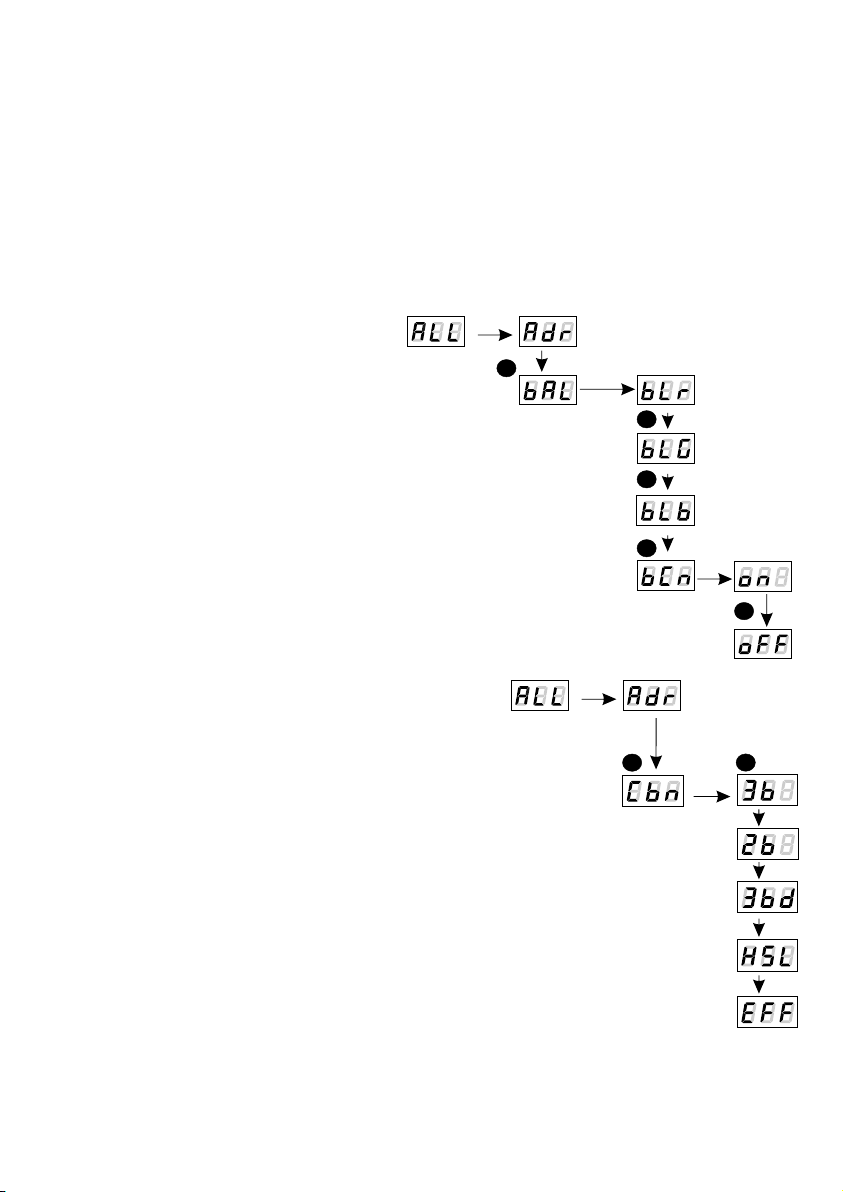
The red channel is marked
with the rEd symbol.
The green channel is
marked with the Grn symbol.
The blue channel is marked
with the bLu symbol.
The intensity of each of them
is controlled in the range
from 0 up to 255.
on switches on all outputs at 100 %, while
oFF switches off the outputs completely.
To manually
program a stage,
you must enter the
Sc option.
To activate the
NO SIGNAL
function, you
need to enter
the noS option.
NEXT
Funkcja ta jest wykorzystywana zarówno do zabezpieczenia instalacji przed zanikiem sygnału
DMX jak i do uzyskania sterowania diodami LED bez podłączania zewnętrznego sterownika. Po
jej uaktywnieniu w przypadku braku sygnału DMX moduł będzie realizował wybraną funkcję
samodzielnie. Ponowne podłączenie sygnału DMX automatycznie przerwie realizowana funkcję
i moduł będzie ponownie realizował przesyłane linią DMX komendy.
ENTER
NEXT
NEXT
PREVIOUS
ENTER
ENTER
NEXT
NEXT
NEXT
NEXT
NEXT
ENTER
NEXT
NEXT PREVIOUS
Możesz skorzystać również z
gotowych 18 programów. Dla
każdego z nich jest również
możliwość ustawienia prędkości
odtwarzania oraz płynności zmian
kroków w programie.
Aby ustawić prędkość odtwarzania, musisz w zakładce
danego programu nacisnąć przycisk „enter”. Pojawi się
napis SPd. Naciśnij ponownie przycisk „enter” i wybierz
odpowiednią wartość z zakresu od 0,1 do 99,9 sekundy.
Aby zatwierdzić te ustawienia naciśnij przycisk „enter”.
Kanał czerwony oznaczony
jest symbolem rEd
Kanał zielony oznaczony
jest symbolem Grn
Kanał niebieski oznaczony
jest symbolem bLu.
Intensywność każdego z
nich regulowana jest w
przedziale 0 - 255.
on oznacza załączenie wszystkich wyjść na
100 %, zaś oFF całkowite wyłączenie wyjść.
Aby samodzielnie
zaprogramować
sceny musisz wejść
w opcję Sc.
Aby uruchomić
funkcję BRAK
SYGNAŁU
musisz wejść w
opcję noS.
NEXTNEXT
ENTER
SPd - czas wejścia
sceny (wartość z
zakresu od 0,1 do 99,9
sekundy)
SPd - czas
załączenia na 100%
(od 0,1 do 99,9
sekundy)
9
NEXT
NEXT
PREVIOUS
ENTER
ENTER
NEXT
NEXT
NEXT
NEXT
NEXT
PREVIOUS
NEXTNEXT
ENTER
SPd - rise time of scene
(values within the range
0,1 ÷ 99,9 s)
SPd - switching time
on 100% (0,1÷99,9 s)

10
12. DESCRIPTION OF PROGRAMS
P01
step 1
R255
255
255
255
255
255
0
0
0
0
0
0
0
0
0
0
0
0
0
0
0
0
0
0
0
0
0
0 0
0
0
0
0
0
0
0
0
0
0
0
0
0
R
R
R
R
R
G
G
G
G
G
G
B
B
B
B
B
B
step 2
step 3
step 4
step 5
step 6
P02 P03 P04 P05 P06 P07 P08 P09 P10
0
255
0
255
0
255
0
0
0
0
0
255
255
255
0
255
255
255
0
255
0
0
255
255
0
0
255
255
0
255
255
0
0
255
0
255
0
0
255
0
255
255
0
255
0
255
255
0
0
255
255
255
0
255
255
0
255
0
0
0
0
255
0
0
255
0
0
255
255
255
0
0
0
0
255
255
255
0
0
0
0
0
0
0
0
0
0
0
0
R
R
R
R
G
G
G
G
B
B
B
B
step 1
step 2
step 3
step 4
P11 P12 P13 P14 P15 P16 P17 P18
0
0
0
255
255
127
127 127
127
127
127
127
127
127
127
127
127
0
0
255
0
0
255
0
0
255
0
255
0
255
0
0
255
0
0
255
0
0
255
0
255
0
0
255
0
255
0
255
255
255
0
0
0
0
0
255
255
255
The following tables show the values for each output channel - R, G and B in programs from 1 up
to 18 (P01 - P18). The value of 255 corresponds to the maximum lightness level on a given
channel, 127 - 50% of power level, 0 - full channel blanking.
The function - to change the rate of step change, you need to click enter on the tab of a
program you are interested in. Then, click the „next” or „previous” buttons to set the FAd
parameter. Then, press the „enter” button and enter a chosen value between 0 (abrupt transition)
up to 100 (completely smooth transition) using the „previous” or „next” buttons. Confirm these
settings by pressing the „enter” button.

13. LIGHT CONTROL FREQUENCY
11
14. SCREEN SAVING (SCREEN BLANKING)
The device is equipped with a feature that allows for turning off the backlight. This option is
marked with the SCr sign. With this feature, the display is turned off after 5s (if the keys of the
device are not pressed). Of course, the device continues its operation without interfering with
other parameters. Press any key to restore the backlight.
1 2
ENTER
ENTER
NEXT
4x
NEXT
To activate the screen saving feature:
1. Set the SCr function and confirm the selection by pressing enter.
2. Use the next or previous buttons to change the value to on and confirm the
selection by pressing enter.
Similarly, select "oFF" to turn off the function.
1 2
ENTER
The Frq function allows for setting the basic control frequency for the LEDs. This function is
extremely useful in applications for the television industry. By applying the "flicker free"
technology, it is possible to avoid the unpleasant flickering effect which is caused by improper
signal synchronization that controls the LEDs. The user can choose from the available frequency
range from 366 Hz up to 1.5 kHz which can be smoothly changed using the previous or next
buttons and selecting a different value.
The frequency value in the upper range (e.g. 1.50 = 1.5 kHz) helps avoid the flickering effects that
are visible in video cameras.
To set the selected range of basic frequencies:
1. Set the Frq function.
2. Set the selected value using the „next” or „previous” buttons.
ENTER
NEXT
3x
NEXT

12
15. SMOOTH
The driver is equipped with a smoothing option. Smooth feature allows for smooth changes in
lightness and colour. When the transition between successive DMX values sent to the lamp is
turned on (e.g. corresponding to changes in lightness) the changes are smooth with no visible
twitches, which prevents the common light "vibrations" effect. Two consecutive DMX values sent
to the lamp are smoothed linearly between the DMX signal packets for the selected option
or the time interval set in the menu.
NEXT
NEXT
ENTER The smoothing function may slightly slow down the
lamp's response rate to changes in the DMX
signal; therefore, it is possible to disable this
option. This can be done by checking the _
parameter and confirming the selection by
pressing „enter”.
Time smoothing enables changing the
time parameter in which subsequent, different
values of the DMX signal sent to the lamp are
smoothed between each other. The minimum
value is 10 [ms] and the maximum is 999 [ms].
ENTER
NEXT
NEXT
...........
NEXT
NEXT
ENTER
ENTER
NEXT
NEXT
NEXT
...........
NEXT
PREV
...........
PREV

13
16. DEFAULT SETTINGS AND MEMORY ERROR (Err)
The device has a feature that allows for restoring default settings.
To use this option, PX254 must be disconnected from the power supply. Before restoring the
power, press and hold the „previous” button. After turning the device on, the message will
appear on the screen (when turning on the power until displaying the previous message,
the „previous” button must be pressed).
This menu designation restores default settings. Accepting this message by pressing the „enter”
key restores default settings. It is also possible to exit this menu without returning to default
settings by pressing the „escape” key.
ź Please note that all set parameters of the PX254 device after restoring the default settings will
be changed to those shown below:
ź DMX address - 1,
ź driver operating mode - RGB (3b - 3-byte),
ź master mode - off,
ź number of sent DMX channels - 128,
ź white balance - off
ź no signal operating mode - Program 1
ź smoothing function (smooth) - off
ź temperature limitation - off
The device is equipped with a built-in memory work control function.
If there are problems with the memory operation on the PX254 display, the message
appears - memory error.
In this situation, select the “enter” key. The device will reload the default configuration and upload
it to the memory. If after this operation, the message remains on the screen, the memory is
permanently damaged and the unit must be sent to the service point.
Err message - memory error
ENTER
POWER ON
PRESSED PREVIOUS
BUTTON
ESCAPE

17. RDM
The PX254 supports the DMX-RDM protocol. DMX protocol allows only of a one-way data
transmission, while its extension the RDM protocol can transmit information in two directions.
This makes possible to simultaneously send and receive information, and hence the possibility of
monitoring activities of the compatible devices. Thanks to RDM some available settings of
compatible devices may be programmed using this protocol.
Below is a list of RDM parameters supported by the PX254:
14
! SUPPORTED_PARAMETERS - all supported parameters - PID: 0x0050;
! PARAMETER_DESCRIPTION - additional parameters description - PID: 0x0051;
! DEVICE_INFO - information about device - PID: 0x0060;
! SOFTWARE_VERSION_LABEL - firmware version of device - PID: 0x00C0;
! DMX_START_ADDRESS - start DMX address of device - PID: 0x00F0,
Editable parameter. Minimal value is 1 and max. 512. According to the RDM
standard for the device, whose footprint is 0, the value of this parameter may be
65535 and then the initial address settings of entire device can not change. DMX
addres can be set only for subdevices;
! IDENTIFY_DEVICE - allows to identify a device - PID: 0x1000,
Editable parameter. You can set it into two states: the identification disabled (0x00),
and identifying enabled (value 0x01);
! STATUS_MESSAGES - information about device status - PID: 0x0030;
! DEVICE_MODEL_DESCRIPTION - device description e.g. name - PID: 0x0080;
! MANUFACTURER_LABEL - e.g. name of manufacturer - PID: 0x0081;
! DEVICE_LABEL - additional device description - PID: 0x0082,
Editable parameter. It is possible to enter additional description of the device using
up to 32 ASCII characters (characters available on a standard QWERTY keyboard);
!
Editable parameter. The selectable DMX work modes are listed below:
1) RGB mode (see item 9 of this manual) - a value of 1;
2) 2B mode (see point 9) - a value of 2;
3) RGBD mode (see point 9) - a value of 3;
4) The HSL mode (see point 9) - the value of 4;
5) EFFECT mode (see point 9) - the value of 5;
! DMX_PERSONALITY_DESCRIPTION - description of particular work modes - PID: 0x00E1;
! DEVICE_HOURS - operating time counted in hours - PID: 0x0400;
! BALANS_RED - value of control level of red chanel balance - PID: 0x8011,
Editable parameter. Minimum value is 0 and maximum is 100 (the value equals to
pecentage of control level). For the maximum value (100) the LEDs work with
maximum brightness. Default value is 100.
! BALANS_GREEN - value of control level of green chanel balance - PID: 0x8012,
Editable parameter. Similar as in the preceding paragraph only for green channel;
! BALANS_BLUE - value of control level of blue chanel balance - PID: 0x8013,
Editable parameter. Similar as in the preceding paragraph only for blue channel;
DMX_PERSONALITY - DMX working mode - PID: 0x00E0,

!
PID: 0x801A, Editable parameter. At 0 value Smooth is turned off, for a value of 1
Smooth mode is set to a Packet to Packet (P2P) and for the value of 2 Smooth is in
time mode (TIM-description in 14th point). The default value is 0 - Smooth off;
! SMOOTH_TIME – Smooth time for TIM function chosen in subsection above -
PID: 0x801B, Editable parameter. Unit in [ms]. Minimal value of this parameter is
10 and maximal 999 [ms]. Default value is 200.
! NO_SIG_P1-18|SC_19|ON_20|OFF_21 - choice of work mode for No DMX signal -
PID: 0x801C, Editable parameter. Minimal Value is 1, maximal 21. For values 1-18
menu allows to chose program from 1 to 18 which is played during no DMX signal
detection. For the 19 value a scene saved in memory is set and for the 20 value all
outputs are set to ON with maximum value. The value 21 sets to OFF all outputs
during time with no DMX signal received. Default value is 21;
! SCENE_RED - settings of red channel value for scene saved in PX282 -
PID: 0x801D, Editable parameter. Minimal value is 0, maximal 255 (maximal
brightness). By defualt value set to 255;
! SCENE_GREEN - settings of green channel value for scene saved in PX282 -
PID: 0x801E, Editable parameter. Similarly as in the subsection above;
! SCENE_BLUE - settings of blue channel value for scene saved in PX282 -
PID: 0x801F, Editable parameter. Similarly as in the subsection above;
! SCREENSAVER_ON/OFF - settings of screensaver (display backlight in PX282) -
PID: 0x8024, Editable parameter. With the 0 value display blanking is not active,
the 1 value means screensaver active. Default value is 0;
SMOOTH_DIS_0/P2P_1/TIM_2 - the choice of options relating to the Smooth function -
15
ź
PID: 0x8025, Editable parameter. Minimum value is 1 and maximal 999 (maximum
speed). By default it is set to 10. Value 1 represents 0,1s, and 999 - 99,9s;
ź PROGRAM_FADE - settings of smooth transition between following steps of a program -
PID 0x8026, Editable parameter. The minimum value is 0 (step transition) a
maximum of 100 (transition completely smooth). The default value is 100;
ź BALANCE ON / OFF - to activate or deactivate the balance of output channels -
PID 0x8027, Editable parameter. A value of 0 is a balance off, a value of 1 active
balance. The default value is set to 0;
ź PWM_FREQENCY - LEDs refresh frequency - PID 0x8028, Editable parameter.
The minimum value is 366 and the maximum is 25000. The unit is [Hz] and the
default value is 366.
ź SERIAL_NUMBER - device serial number - PID: 0x8030, Editable parameter.
The minimum value is 0, and the maximum is 4294836225. The default value is 0.
PROGRAM_SPEED - programs playback speed settings (playing next steps of program) -
ź DISPLAY_FLIP - inverting the meter display 180 degrees - PID: 0x8031, Editable
parameter. The minimum value is 0, and the maximum is 1. The default value is 0.

NEXT
PREVIOUS
ENTER
ENTER
NEXT
NEXT
NEXT
PREVIOUS
18. PROGRAMMING - MENU TREE NOTES:
1. ENTER allows for entering a
subsequent "submenu" and saving a
selected parameter.
2. ESCAPE allows for returning to the
previous menu without saving changes.
3. NEXT allows for moving forward within
the selected menu.
4. PREVIOUS allows for moving
backward within the selected menu.
ENTERENTER
NEXT
ENTER
ENTER
ENTER
ENTER
ENTER
NEXT
ENTER
PREVIOUS
NEXT
NEXT
NEXT
NEXT
NEXT
NEXT
NEXT
NEXT
NEXT
NEXT
ENTER ENTER
ENTER
NEXT
NEXT
ENTER
ENTER
NEXT
ENTER
NEXT
ENTER
ENTERENTER
NEXT
NEXT
ENTER
PREVIOUS
NEXT
NEXT
NEXT
NEXT
NEXT
ENTER
NEXT
NEXT
16
NEXT
NEXT
ENTER
ENTER
NEXT
NEXT
NEXT
ENTERENTER
NEXT
ENTER
ENTER
ENTER
ENTER
ENTER
ENTER
PREVIOUS
NEXT
NEXT
NEXT
NEXT
NEXT
NEXT
NEXT
NEXT
NEXT
NEXT
ENTER ENTER
ENTER
NEXT
ENTER
NEXT
ENTER
ENTER
ENTERENTER
NEXT
NEXT
ENTER
PREVIOUS
NEXT
NEXT
NEXT
NEXT
NEXT
ENTER
NEXT
NEXT
NEXT
PREVIOUS
NEXT
PREVIOUS
NEXT
ENTER
NEXT
PREVIOUS
ENTER
NEXT
NEXT
NEXT
ENTER
PREVIOUS
NEXT
ENTER
NEXT
ENTER
NEXT
NEXT
ENTER

sample connection of LED stripe
17
typical LED stripe
controller DMX
1 2 3 4 5 6
PX015
1 2 3 4 5 6 Chaser Scene
Club 6p
90
% 100
80
70
60
50
40
30
20
10
0
100 %
90
80
70
60
50
40
30
20
10
0
Master
Music Speed
GND
DMX-
DMX+
B
G
R
+12
19. CONNECTION SCHEME
PX254 uses active type DMX, therefore there is no need to use terminators at the end of the DMX
line. With this solution applied, there is no limitation of number devices that can be connected to
the DMX controller (connected in series).
Connections must be made using cables of suitable thickness.
Properly made connections reduce the risk of damaging and improve its reliability. Apply only
shielded cables to connect the DMX signal.
Note: In case of loosing power supply in any devices that work connected in series the following
devices in chain will loose connection with main controller.
B
G
R
+12
Please note that the PX254 driver is
common anode type device!!!
It is possible to connect lamps
with 4-wires cable with a common + only!
7-24VDC
18A max
OUTPUT:
INPUT:
3x6A
PWM
7,5A

18
20. DIMENSIONS
512
7 - 24 V DC
max. 18 A
30 mA for 12 V DC
40 mA for 24 V DC
3
16 bit
1
18
6 A / channel
terminal blocks
YES
0,15 kg
175 mm
43 mm
27 mm (including terminal block)
- DMX channels
- power supply
- current consumption
- no-load current consumption
- output channels number
- control accuracy
- programmable scenes
- built-in programs
- outputs load capacity
- output sockets
- MASTER mode
- weight
- dimensions:,
- width
- heigth
- depth
21. TECHNICAL DATA
175 mm
27 mm 42 mm
21 mm

19
PXM Marek Żupnik sp. k.
ul. Przemysłowa 12
30-701 Kraków, Poland
LED Driver 3 x 6A OC
PX254
PN-EN 61347-2-13:2008
PN-EN 61000-6-1:2008
PN-EN 61000-6-3:2008
The DMX-512 output must be shielded and the
shielding must be connected to the ground
responding to the DMX connectors.
mgr inż. Marek Żupnik.
Name of producer:
Manufacturer’s address:
We declare that our product:
Product name:
Product code:
complies with the following standards:
LVD:
EMC:
Additional information:
Kraków, 15.07.2014
DECLARATION OF CONFORMITY
according to guide lines 2004/108/EC and 2006/95/EC
stage and theatre consoles digital dimmers dmx systems architectural lighting controllers led lighting
tel: +48 12 626 46 92
fax: +48 12 626 46 94
e-mail: [email protected]
http://www.pxm.pl
ul. Przemysłowa 12
30-701 Kraków, Poland
Other manuals for PX254
1
Table of contents
Other PXM DC Drive manuals
Popular DC Drive manuals by other brands

WEG
WEG CFW-11 Series user manual

eldoLED
eldoLED LINEARdrive 720D Wiring diagram

Aumuller
Aumuller KS 2 Assembly and commissioning instructions

Addonics Technologies
Addonics Technologies AD25MSD user guide

GFA
GFA ELEKTROMAT SI 100.30 FU-55,00 10003917 10011 installation instructions

CUH
CUH SDVC34 Series Instruction book