manuals.online logo
Brands
  1. Home
  2. •
  3. Brands
  4. •
  5. Pyle
  6. •
  7. Car Stereo System
  8. •
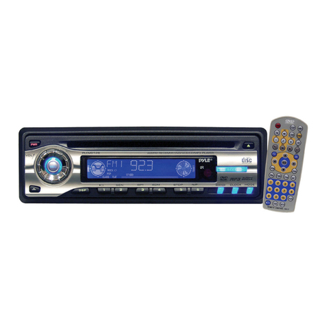
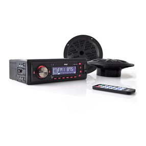
  9. Pyle PLCD41MU User manual

Pyle PLCD41MU User manual

Other Pyle Car Stereo System manuals

Pyle PBT92 User manual

Pyle

Pyle PBT92 User manual

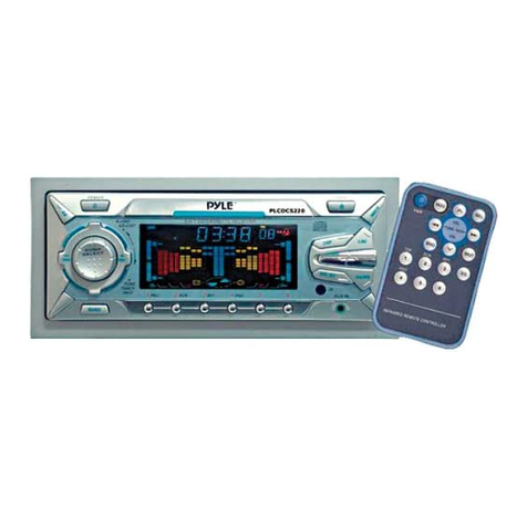
Pyle PLCDCS220MP User manual

Pyle

Pyle PLCDCS220MP User manual

Pyle PLMCA40 Cycle Series User manual

Pyle

Pyle PLMCA40 Cycle Series User manual

Pyle PLMR14W User manual

Pyle

Pyle PLMR14W User manual

Pyle Plus PLCD71 User manual

Pyle

Pyle Plus PLCD71 User manual

Pyle View PLTNV66 User manual

Pyle

Pyle View PLTNV66 User manual

Pyle PLDMN65 Quick start guide

Pyle

Pyle PLDMN65 Quick start guide

Pyle Plus PLCD72MP User manual

Pyle

Pyle Plus PLCD72MP User manual

Pyle PLDTN68 User manual

Pyle

Pyle PLDTN68 User manual

Pyle PLDVD132 User manual

Pyle

Pyle PLDVD132 User manual

Pyle PLR15MUA User manual

Pyle

Pyle PLR15MUA User manual

Pyle PYLE PL90MU User manual

Pyle

Pyle PYLE PL90MU User manual

Pyle PLDVD138 User manual

Pyle

Pyle PLDVD138 User manual

Pyle PLMRKT12 User manual

Pyle

Pyle PLMRKT12 User manual

Pyle PLCD5MRBTS User manual

Pyle

Pyle PLCD5MRBTS User manual

Pyle PLCD44 User manual

Pyle

Pyle PLCD44 User manual

Pyle 189 Quick start guide

Pyle

Pyle 189 Quick start guide

Pyle PBT9 User manual

Pyle

Pyle PBT9 User manual

Pyle PLCD65WXMU User manual

Pyle

Pyle PLCD65WXMU User manual

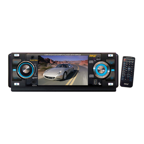
Pyle PLD57MU User manual

Pyle

Pyle PLD57MU User manual

Pyle PL97M4 User manual

Pyle

Pyle PL97M4 User manual

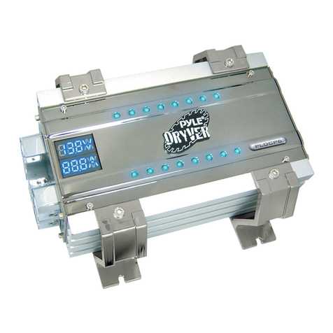
Pyle PLDCP6 User manual

Pyle

Pyle PLDCP6 User manual

Pyle PYLE PLVSMR7 User manual

Pyle

Pyle PYLE PLVSMR7 User manual

Pyle PYLE Plus Series PLCDUSB78MP3 User manual

Pyle

Pyle PYLE Plus Series PLCDUSB78MP3 User manual

Popular Car Stereo System manuals by other brands

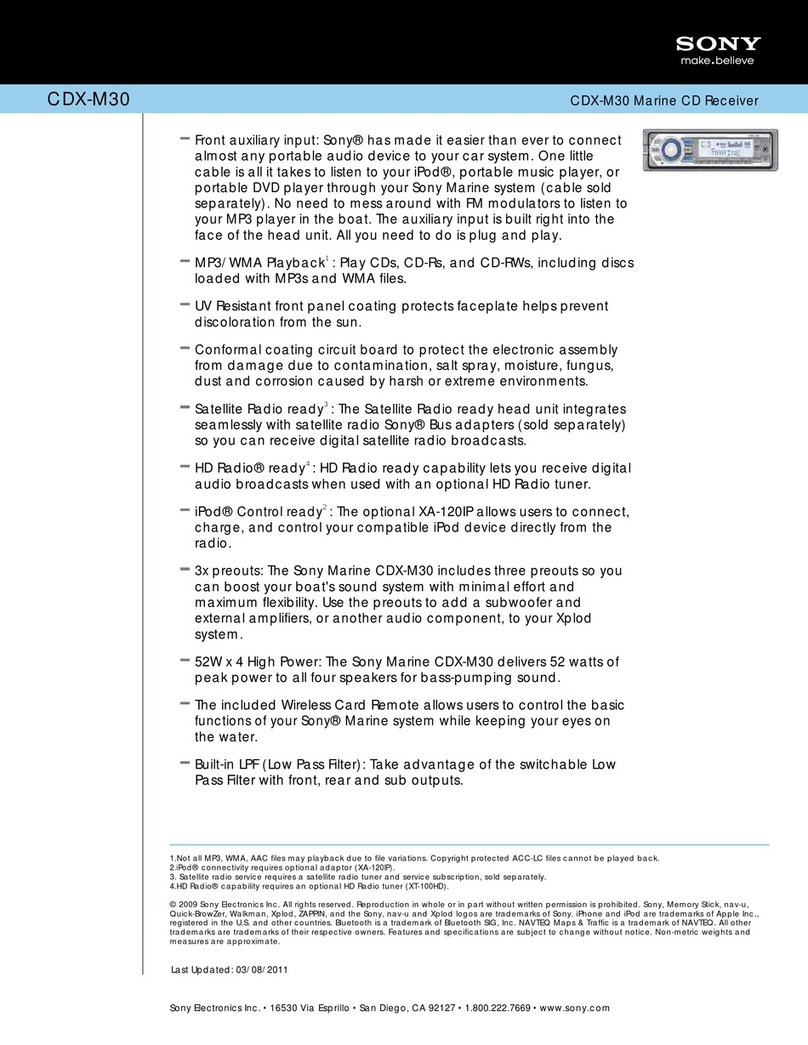
Sony CDXM60UI - Marine CD Receiver MP3/WMA/AAC... Features
Sony

Sony CDXM60UI - Marine CD Receiver MP3/WMA/AAC... Features

Philips CED780/98 quick start guide

Philips

Philips CED780/98 quick start guide

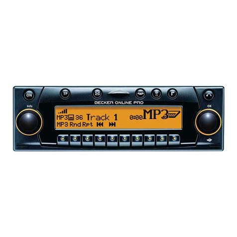
Becker Online Pro 7800 installation guide

Becker

Becker Online Pro 7800 installation guide

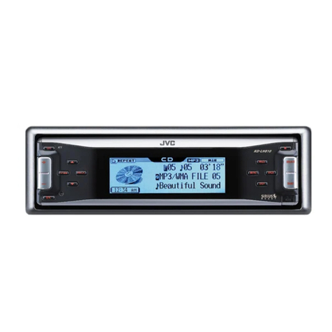
JVC KD-LH810 instructions

JVC

JVC KD-LH810 instructions

Clarion PU-9836A Service manual

Clarion

Clarion PU-9836A Service manual

Sony RM-X7BT reference guide

Sony

Sony RM-X7BT reference guide

Mitsubishi Electric AR0M manual

Mitsubishi Electric

Mitsubishi Electric AR0M manual

Insignia NS-HD5113 user guide

Insignia

Insignia NS-HD5113 user guide

Clarion BTD3341 user manual

Clarion

Clarion BTD3341 user manual

USA SPECS PA11-VW6 owner's manual

USA SPECS

USA SPECS PA11-VW6 owner's manual

Sony MEX-N4380BT operating instructions

Sony

Sony MEX-N4380BT operating instructions

Kenwood KCD-BT6544U/UY Service manual

Kenwood

Kenwood KCD-BT6544U/UY Service manual

JVC KD-DB912BT instruction manual

JVC

JVC KD-DB912BT instruction manual

Philips CSQ405/98 user manual

Philips

Philips CSQ405/98 user manual

Alpine TDM-7544 Specifications

Alpine

Alpine TDM-7544 Specifications

JL Audio Stealthbox SB-CAN-G2MVX3D/10TW3 installation guide

JL Audio

JL Audio Stealthbox SB-CAN-G2MVX3D/10TW3 installation guide

Denso TEN FT0108A user manual

Denso TEN

Denso TEN FT0108A user manual

Harman Chrysler Radio Navigation System RB4 user manual

Harman

Harman Chrysler Radio Navigation System RB4 user manual

manuals.online logo
manuals.online logoBrands
  • About & Mission
  • Contact us
  • Privacy Policy
  • Terms and Conditions

Copyright 2025 Manuals.Online. All Rights Reserved.

-1-
Content
Installation steps...........................................................................
General information about remote control......................................
1. Removing insulating sheet.........................................................
2. Replacing the lithium cell...........................................................
3. Note about using the remote control...........................................
4. Warning about lithium cells of remote control.............................
Locations and Names of controls...................................................
1. Locations and Names of controls on main unit............................
2. Locations and Names of controls on remote control...................
General operation...........................................................................
Radio operation.............................................................................
Disc/USB/card operation............ ...................................................
1. Loading or unloading a disc, USB or card..................................
1.1 Loading a disc, USB or card.....................................................
1.2 Unloading a disc, USB or card..................................................
2. Function of controls on main unit or remote control..................
AUX IN operation...........................................................................
Troubleshooting............................................................................
Specifications...............................................................................
2
6
6
6
6
6
7
7
8
9
10
12
12
12
12
13
15
16
17
INSTALLATION STEPS
1. Remove 2 screws for protecting deck;
1) Remove chassis from the Slide Bracket Housing as follows:
2) Remove 2 screws protecting the deck as
right;
2. Connecting all wires
1) Slide Bracket Housing;
2) Remove the control panel from the chassis as follows:
A. Press REL button to detach the control panel .
B. Hold the right end of the control panel to pull rightward
illustrated on the
Re-insert the chassis into the
a little and then remove it
REL button
PLASTIC TRIM OUT
KEY PLATE
KEY PLATE
If you want to remove the chassis from the Slide Bracket Housing , first remove the
Plastic trim from both sides, then insert 2 Key Plates into the left and the right side of
the chassis as illustrated.
-2-
-3-
3) Connecting all wires as bellows:
IGNITION SWITCH
RED
WHITE
WHITE/BLACK
GREY
GREY/BLACK
GREEN
GREEN/BLACK
VIOLET
VIOLET/BLACK
YELLOW
CONSTANT 12 VOLTS
BLACK GROUND(B-)
BLUE AUTO ANTENNA
FRONT
Lch SPK.
REAR
Lch SPK.
FRONT
Rch SPK.
REAR
Rch SPK.
RADIO ANTENNA JACK
FRONT AUDIO OUT RCA JACK R (red)
FRONT AUDIO OUT RCA JACK L (white)
REAR AUDIO OUT RCA JACK L (white)
REAR AUDIO OUT RCA JACK R (red)
NOTE:
1. Must use 4 ohms impedance of speakers.
2. Before finishing wiring, do not attach control panel onto chassis.
3. Maximum current of auto antenna is 200mA.
ISO CONNECTOR
FUSE
FUSE
4) Attaching the control panel onto the chassis.
A. Align and thrush the bulge of the control panel into the hollow of the chassis.
B. Push the right end of the control panel to the chassis till a click sound is heard.
* How to clean panel connector
Frequent detachment will cause the panel connectors to deteriorate. To minimize
deterioration, periodically wipe the panel connector with a clean/soft/dry cloth .
5) Test to make sure that it works properly.
3. Instal the main unit according to the installation diagram on the next page:
1) Mount the main unit in A/V position in vehicle.
2) Bend tabs of the sliding metal housing where necessary to ensure that
the front part of main unit is fixed;
3) Use a metal strap to fix the rear part of the chassis.
* Uninstalling the main unit:
1) Remove the metal strap from the main unit;
2) Remove the plastic trim frame from the main unit;
3) Insert a key plate into the left and the right side of the main unit and draw the
main unit out of the sliding metal housing.
Bulge
Hollow
Panel Connector
-4-
-5-
Installation diagram
DASH BOARD
METAL MOUNTING
STRAP
HEX NUT
SPRING WASHER
PLAIN WASHER
TAPPING SCREW
CONSOLE
SLIDE BRACKET
HOUSING
HEX BOLT
-6-
General information about the remote control
1. Removing insulating sheet
The remote control comes with an insulating
sheet attached to the underside of the remote
control as illustrated on the right
The remote control is disabled and will not work
until the insulating sheet is removed.
as illustrated on the right
.
2. Replacing the lithium cell
If the electric energy of the lithium cell is weak,
replace it .
1. Press and hold the movable block in the
direction indicated by arrow 1 , at the same
time pull the cell holder out of the remote control
in the direction indicated by arrow 2 .
2. Replace the old cell with a new one with (+)
polarity side upward .
3. Insert the cell holder into the remote control again.
3. Note about using the remote control
1. Face the emitting window of the remote control towards the sensor window of
the unit.
2. Operation angle for front panel: About 30 degrees
3. The distance between the emitting window of the remote control and the sensor
window of the unit : < 5M .
4. Warning for lithium cells of remote control
leakage may cause damage to remote control.1.Cell
2.Do not throw cells into fire, it may cause an explosion.
3.To avoid accidents, keep cells out of reach of children.
Locations and Names of controls
1. Locations and Names of controls on main unit
-7-
1823
1. REL button
2. PWR button
3. SEL button and VOL knob
4. BAND or ID3 button
5. TA or AF button
6. APS button
7. MUTE or PTY button
8. >|| or 1 button
9. INT or 2 button
10.RPT or 3 button
11.RDM or 4 button
12.-10 or 5 button
13.+10 or 6 button
14. |<< button
15. >>| button
16. MODE button
17. EJECT button
18. RESET button
19. IR sensor window
20. AUX IN jack
21. USB port
22. LCD screen
23. Card slot
24. CLK button
25. Disc slot
Control Panel
Front side of chassis after removing control panel
2
31
7
6
9814
15 17 19
20
21
22
25
4510 11 12 13
16
24
TA/AF
MU/ PT Y
2. Locations and Names of controls on remote control
-8-
PWR
MUTE
VOL-
SEL
ENTER
AF
VOL+
TA
MOD DISP
ID3
BAND
APS
SEARCH
SCAN
123
456
/TOP
INT
-10
RPT
RDM
+10
PTY
1
2
3
5
6
8
9
11
4
7
10
12
13
14
15
16
17
18
19
20
21
1. PWR button
2. < button
3. AF button
4. VOL- button
5. TA button
6. ID3 or BAND button
7. APS or SEARCH button
8. >|| or TOP or 1 button
9. RDM or 4 button
10.INT or 2 button
11. VOL+ button
12. MUTE button
13. SEL or ENTER button
14. > button
15. PTY button
16. DISP button
17. MODE button
18. SCAN button
19. RPT or 3 button
20. +10 or 6 button
21. -10 or 5 button
General Operation
1. PWR button
To power main unit on or off.
2. VOL knob or VOL+ & VOL- button
To increase or decrease volume level.
3. MUTE button
To cancel or resume sound, long press the MUTE button on control panel or short
press the MUTE button on remote control.
4. SEL button
5. DISP or CLK button
To display clock time, briefly press the DISP or CLK button.
To set clock time, first long press the DISP or CLK button to flash hour, and rotate
the VOL knob or press the VOL+ or VOL- button to adjust the hour; then briefly
press the SEL button to flash minute, and rotate the VOL knob or press the VOL+
or VOL- button to adjust the minutes; finally press the DISP or CLK button to con-
firm it.
6. MODE button
To switch on a work source between RADIO, DISC, USB, CARD and AUX IN.
7. REL button
To detach the control panel from chassis.
8. RESET button
To reset all parameters to factory default values.
* When LCD does not display normally or sound is distorted or some controls are
disabled, press the REL button to detach the control panel from chassis and re-
move the control panel from the chassis, then use a subject with a sharp point
end to thrush the RESET hole.
To switch between VOL(volume), BAS(bass), TRE(treble), BAL(balance), FAD
(fader), EQ, BEEP, LOUD, MONO/STEREO(in radio mode) and LOC/DX(in radio
mode), press the SEL button repeatedly. After selecting a desired mode, rotate
the VOL knob or press the VOL+ or VOL- button to set it.
To switch between TA SEEK/ALAR, MASK AL/DP, RETUNE S/L and TA VOL 25,
long press the SEL button to switch on TA SEEK/ALAR, then short and repeatedly
press the SEL button. After selecting a desired mode, rotate the VOL knob or
press the VOL+ or VOL- button to set it.
-9-