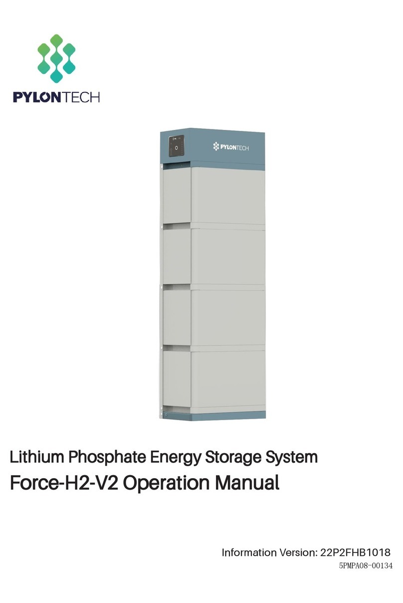
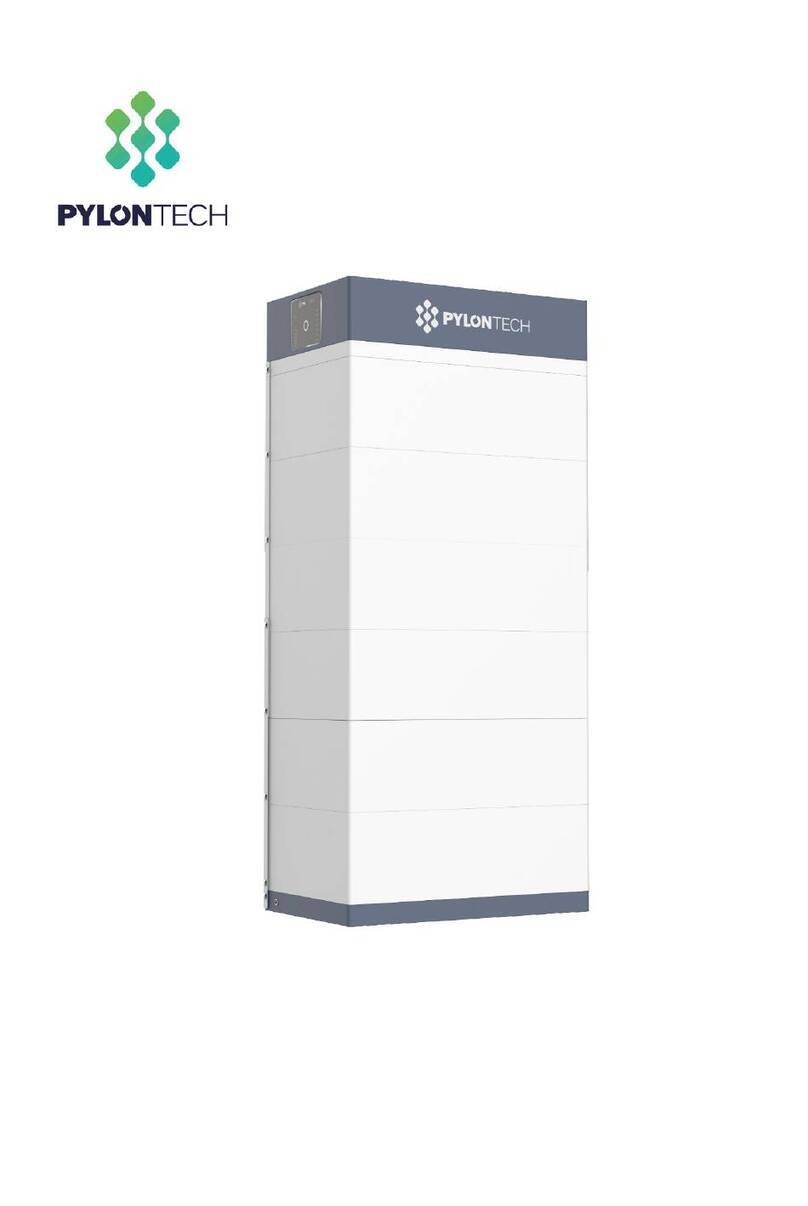
Pylontech Force-H1-V2 User manual

Lithium-Ion Phosphate Energy Storage System
Force-H1-V2 Operation Manual
Information Version: 22P1FH1018
5PMPA08-00135


This manual introduces Force-H1-V2 from Pylontech. Force-H1-V2 is a high voltage Lithium-Ion
Phosphate Battery storage system. Please read this manual before you install the battery and follow
the instruction carefully during the installation process. Any confusion, please contact Pylontech
immediately for advice and clarification.
Content
1. Safety .........................................................................................................................................................1
1.1 Symbol .............................................................................................................................................. 2
1.2 Before Connecting................................................................................................................................ 5
1.3 In Using ................................................................................................................................................ 5
2. System Introduce .......................................................................................................................................6
2.1 Product Introduce ............................................................................................................................. 6
2.2 Specifications .................................................................................................................................... 6
2.2.1 System Parameter.......................................................................................................................... 7
2.2.1.1 Single group system parameter ................................................................................................ 7
2.2.1.2 Multi-groups system parameter (Max. 6 groups per system)................................................... 9
2.2.2 Battery Module (FH48074) ............................................................................................................. 10
2.2.3 Control Module FC0500-40S-V2 (internal power supply)............................................................... 11
2.3 System Diagram .............................................................................................................................. 17
3. Installation ...............................................................................................................................................18
3.1 Tools................................................................................................................................................ 18
3.2 Safety Gear...................................................................................................................................... 19
3.3 System Working Environments Checking........................................................................................ 20
3.3.1 Cleaning ....................................................................................................................................... 20
3.3.2 Ventilation.................................................................................................................................... 20
3.3.3 Fire-extinguisher System.............................................................................................................. 20
3.3.4 Grounding System........................................................................................................................ 20
3.3.5 Clearance ..................................................................................................................................... 20
3.4 Handling and placement................................................................................................................. 21
3.4.1 Handling and placement of the battery module.......................................................................... 21
3.4.2 Handling and placement of the base........................................................................................... 21
3.4.3 Selection of installation sites ....................................................................................................... 21
3.4.4 Packing list ................................................................................................................................... 22
3.4.5 Mounting and installation of the base......................................................................................... 23
3.4.6 Battery Modules and Control Module (BMS) pile up................................................................... 23
3.4.7 Installation of the metal bracket for the system.......................................................................... 24
3.4.8 Locking of the control Module’s fix screw of left and right side.................................................. 27
3.5 Cables connection........................................................................................................................... 28
3.5.2 Cables........................................................................................................................................... 30
3.5.3 Multi-groups battery wiring diagram.............................................................................................. 32
3.5.3 System turns on .............................................................................................................................. 34
3.5.3.1 Single group system turns on.................................................................................................. 34

3.5.3.2 Multi-groups system turns on................................................................................................. 36
3.5.4 System turns off.............................................................................................................................. 37
4. System Debug ..........................................................................................................................................38
5. Maintenance............................................................................................................................................39
5.1 Trouble Shooting:............................................................................................................................... 39
5.2 Replacement of main component...................................................................................................... 41
5.2.1 Replacement of Battery Module..................................................................................................... 41
5.2.2 Replacement of Control Module (BMS).......................................................................................... 43
5.3 Battery Maintenance ...................................................................................................................... 44
6. Remarks ...................................................................................................................................................44
7. Shipment..................................................................................................................................................46
Annex 1: Installation and System Turn ON Progress List.....................................................................................47
Annex 2: System Turn OFF Progress List .............................................................................................................48

1
1. Safety
The Force-H1-V2 is a high voltage DC system, operated by skilled/qualified personnel only. Read
all safety instructions carefully prior to any work and observe them at all times when working on
with the system.
Incorrect operation or work may cause:
➢injury or death to the operator or a third party.
➢damage to the system hardware and other properties belonging to the operator or a third
party.
Skills of Qualified Personnel
Qualified personnel must have the following skills:
⚫training in the installation and commissioning of the electrical system, as well as the dealing
with hazards;
⚫knowledge of this manual and other related documents;
⚫knowledge of the local regulations and directives.

2
1.1 Symbol
Danger
Lethal voltage!
⚫Battery strings will produce HIGH DC power and can
cause a lethal voltage and an electric shock.
⚫Only qualified person can perform the wiring of the
battery strings.
Warning
Risk of battery system damage or personal injury
⚫DO not pull out the connectors while the system is
working!
⚫De-energize from all multiple power sources and verify
that there is no voltage.
Caution
Risk of battery system failure or life cycle reduces.
Symbol in
label
Read the product and operation manual before operating
the battery system!
Symbol in
label
Danger! Safety!
Symbol in
label
Warning electric shock!
Symbol in
label
Do not place near flammable material
Symbol in
label
Do not reverse connection the positive and negative.

3
Symbol
in label
Do not place near open flame
Symbol
in label
Do not place at the children and pet touchable area.
Symbol
in label
Recycle label.
Symbol
in label
Label for Waste Electrical and Electronic Equipment (WEEE)
Directive (2012/19/EU)
Symbol
in label
The certificate label for EMC.
Symbol
in label
The certificate label for Safety by TÜV SÜ D.
Symbol
in label
The certificate label for Safety by CSA.

4
Danger: Batteries deliver electric power, resulting in burns or a fire hazard when they are
short circuited, or wrongly installed.
Danger: Lethal voltages are present in the battery terminals and cables. Severe injuries or
death may occur if touch the cables and terminals.
Warning: DO NOT open or deform the battery module, otherwise the product will be out of
warranty scope
Warning: Whenever working on the battery, wear suitable personal protective equipment
(PPE) such as rubber gloves, rubber boots and goggles.
Warning: Force-H1-V2 system working temperature range: 0 ℃~50 ℃; Optimum
temperature: 18℃~28℃. Out of the working temperature range may cause the
battery system over / low temperature alarm or protection which further lead to
the cycle life reduction as well as. It will affect the warranty terms as well.
Warning: For battery installation, the installer shall refer to NFPA70 or similar local
installation standard for operation.
Caution: Improper settings or maintenance can permanently damage the battery.
Caution: Incorrect inverter parameters will lead to a further faulty/damage to battery.
Reminding
1) It is very important and necessary to read the user manual carefully (in the accessories)
before installing or using battery. Failure to do so or to follow any of the
instructions or warnings in this document can result in electrical shock, serious
injury, or death, or can damage battery, potentially rendering it inoperable.
2) If the battery is stored for long time, it is required to charge them every six months, and
the SOC should be no less than 90%;
3) Battery needs to be recharged within 12 hours, after fully discharged;
4) Do not expose cable outside;

5
1.2 Before Connecting
1) After unpacking, please check product and packing list first, if product is damaged or lack
of parts, please contact with the local retailer;
2) Before installation, be sure to cut off the grid power and make sure the battery is in the
switched-off mode;
3) Wiring must be correct, do not mistake the positive and negative cables, and ensure no
short circuit with the external device;
4) It is prohibited to connect the battery and AC power directly;
5) Battery system must be well ground and the resistance must be less than 100mΩ;
6) Please ensured the electrical parameters of battery system are compatible to related
equipment;
7) Keep the battery away from water and fire.
1.3 In Using
1) If the battery system needs to be moved or repaired, the power must be cut off and the
battery is completely shut down;
2) It is prohibited to connect the battery with different type of battery.
3) It is prohibited to put the batteries working with faulty or incompatible inverter;
4) It is prohibited to disassemble the battery (QC tab removed or damaged);
5) In case of fire, only dry powder fire extinguisher can be used, liquid fire extinguishers are
prohibited;

6
2. System Introduce
2.1 Product Introduce
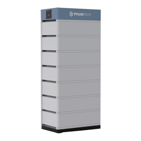
Force-H1-V2 is a high voltage battery storage system based on lithium iron phosphate battery,
which is one of the new energy storage products developed and produced by Pylontech. It can
be used to support reliable power for various types of equipment and systems. Force-H1-V2
enabled multiple strings` parallel operation feature, which provide tremendous flexibility in
system design and configuration. Force-H1-V2 is especially suitable for those application scenes
which required high power output, limited installation space, restricted load-bearing and long
cycle life.
2.2 Specifications

7
2.2.1 System Parameter
2.2.1.1 Single group system parameter
Product Type
Force-H1-V2
Cell Technology
Li-iron (LFP)
Battery System
Capacity(kWh)
7.10
10.65
14.20
17.76
21.31
24.86
Battery System
Voltage (Vdc)
96
144
192
240
288
336
Battery System
Capacity (AH)
74Ah
Battery Controller
Name
FC0500-40S-V2
Battery Module Name
FH48074
Battery Module
Quantity(pcs)
2
3
4
5
6
7
Battery Module
Capacity(kWh)
3.552
Battery Module
Voltage (Vdc)
48
Battery Module
Capacity (AH)
74
Battery System Charge
Upper Voltage (Vdc)
108
162
216
270
324
378
Battery System Charge
Current (Amps,
Standard)
14.8
Battery System Charge
Current (Amps,
Normal)
37
Battery System Charge
Current (Amps,
Max.@15s)
42
Battery System
Discharge Lower
Voltage (Vdc)
87
130.5
174
217.5
261
304.5
Product Type
Force-H1-V2

8
Battery System
Discharge Current
(Amps, Standard)
14.8
Battery System
Discharge Current
(Amps, Normal)
37
Battery System
Discharge Current
(Amps, Max.@15s)
42
Short circuit rating
(Amps)
<4000
Efficiency (%)
96
Depth of Discharge
(%)
95
Dimension(W*D*H,
mm)
600*380*
530
600*380*
700
600*380*
870
600*380*
1040
600*380*
1210
600*380*
1380
Communication
CANBUS/Modbus RTU
Protection Class
IP55
Weight (kg)
86
122
158
194
230
266
Operation Life (Years)
15+
Operation
Temperature(℃)
0~50℃
Storage
Temperature(℃)
-20~60℃
Altitude(m)
<2000
Humidity
5~95%
Product Certificate
VDE-AR-E 2510-50, IEC62619, IEC63056, IEC62040-1,
2014/53/EU(RED),UL1973
Transfer Certificate
UN38.3
1) Battery Controller
Dimensions (W*D*H)
600×380×150mm
2) Battery Module
Dimensions (W*D*H)
600×380×170mm
3) Battery bottom
base Dimensions
(W*D*H)
600×380×40mm

9
2.2.1.2 Multi-groups system parameter (Max. 6 groups per system)
For multi-groups operation, please make sure the battery type in the whole system is the same,
please make sure the battery amount of each group is the same.
Product Type
Force-H1-V2 in multi-groups
Battery System Voltage(Vdc)*
96/144 / 192 / 240 / 288 / 336
Battery System group amount(pcs)
2
3
4
5
6
Battery System capacity (AH)
148
222
296
370
444
Battery System Operation
Current(Amps, Standard)
29.6
44.4
59.2
74
88.8
Battery System Operation
Current(Amps, Normal)
74**
111**
148***
185***
222***
Battery System Operation Current
(Amps, Max.@15s)
84**
126**
168***
210***
252***
P-Combiner-HV-3/6 Operation
Current (Amps, Normal)
50
100
P-Combiner-HV-3/6 Operation
Current (Amps, Max.@15s)
80
160
*The Battery System Voltage is varying depends on battery amount in serial per group.
**The current is based on BMS theoretical operation current to consider. If use P-Combiner-HV-
3 as the combiner box of the multi-groups` battery system wiring connection, the max.
continuous operation current is 50Amps, max. peak operation current is 80Amps for 15sec. for
the battery system. Please make sure the real operation current not exceed the combiner box
power rating.
***The current is based on BMS theoretical operation current to consider. If use P-Combiner-
HV-6 as the combiner box of the multi-groups` battery system wiring connection, the max.
continuous operation current is 100Amps, max. peak operation current is 160Amps for 15sec.
for the battery system. Please make sure the real operation current not exceed the combiner
box power rating.

10
2.2.2 Battery Module (FH48074)
Product Type
FH48074
Cell Technology
Li-ion (LFP)
Battery Module Capacity (kWh)
3.552
Battery Module Voltage (Vdc)
48
Battery Module Capacity (Ah)
74
Battery Module Serial Cell Quantity (pcs)
15
Battery Cell Voltage (Vdc)
3.2
Battery Cell Capacity (AH)
37
Dimension (W*D*H, mm)
600*380*170
Weight (kg)
36
Operation Life
15+Years
Operation Cycle Life
5,000
Operation Temperature
0~50℃
Storage Temperature
-20~60℃
Transfer Certificate
UN38.3

11
2.2.3 Control Module FC0500-40S-V2 (internal power supply)
Control Module (FC0500-40S-V2) Display Panel
LED Button
Short Press
Display the LED panel for 20sec.
Long Press 1
(between 5 to
10 seconds)
When status LED fast flashes blue ●, loss the button,
then it is 115200 baud rate of RS485.
When status LED fast flashes orange ●, loss the button,
then it is 9600 baud rate of RS485.
If a special protocol (except Pylontech Protocol), is
selected follow ‘Long Press 2’, then the baud rate
changing described here is ineffective.
Long Press 2
(more than
10sec)
Communication Protocol Selection, for details please
check with Pylontech service team

12
Status
2 colors, Blue and orange
Refer to [LED Indicators Instructions]
Battery Module Status
Blue solid
Normal
Orange solid
Individual module alarm or
protection. See trouble shooting
steps in section 5.1
System Capacity
System SOC
Each LED indicate 25%SOC
Indicate the system SOC.

13
LED Indicators Instructions
Condition
Note
Self-checking
Blue, Flashing
All flashing
Self-checking
failure
Orange, Slow flashing
Off
Battery Module Status
off. See trouble
shooting steps in
section 5.1
Black start
success
Blue, fast flashing
Off
Black start failure
Orange, Fast flashing
Off
See trouble shooting
steps in section 5.1
Communication
Lost or BMS error
Orange, solid
Indicate SOC, blue,
solid
See trouble shooting
steps in section 5.1
Idle
Blue, slow flashing
Indicate SOC, blue,
solid
Charge
Blue, solid
Indicate SOC, blue,
solid
Floating charge
Blue, solid
All flashing, horse race
lamp
Discharge
Blue, flashing
Indicate SOC, blue,
solid
System sleep
Blue, flashing
Off
Battery module status
off
Remark: Slow flashing: 2.0s ON/1.0s OFF. Flashing 0.5s ON/0.5s OFF.
Fast flashing: 0.1s ON/0.1s OFF.

14
Control Module (FC0500-40S-V2) Cable Panel
Power Switch
ON: main breaker ON, able to turn on battery system by start button.
OFF: system turn off completely, no power output.
Caution: When the breaker is tripped off because of over current or short circuit, must wait
more than 30min then can turn on it again, otherwise may cause the breaker damage.
Start Button
Start function: press more than 5sec until
the buzzer rings, to turn on controller.
Multi-groups start up sequence: please start up the last string(from communication
structure, the last slave) of battery system first, one by one to the first string which shall be
start up lastly. Details as below table
Communication Structure
Start-up Sequence
Master string
Last Start up
Slave string 1
5th Start up
Slave string 2
4th Start up (if has)
Slave string 3
3rd Start up (if has)
Slave string 4
2nd Start up (if has)
Slave string 5
1st Start up (if has)

15
Black start function: when system turn on, and relay is OFF, press more than 10sec, and relay
will turn on for 10 min without communication (depends on conditions).
Multi-groups Black Start: Only need perform black start operation on MASTER string, it will
close circuit for one of the strings within the system for 10mins. The slave string black start
function is being solely controlled by master string.

16
Wi-Fi
Manufacturer: Pylon Technologies Co., Ltd.
Address: Plant 8, No.505 Kunkai Road, JinXi Town, 215324 Kunshan City, Jiangsu Province,
PEOPLE'S REPUBLIC OF CHINA
Importer: XXXX (Located in installed country)
Address: XXXX (Located in installed country)
Wireless maximum output power: 20dBm
Operating frequency: 2412-2472MHz
Gain of antenna: Max 3dBi
Modulation system:
DBPSK/DQPSK/CCK(DSSS)
BPSK/QPSK/16QAM/64QAM(OFDM)
Modulating Repetition:
1Mbps/2Mbps/5.5Mbps/11Mbps (DSSS)
6Mbps/9 Mbps/12 Mbps/18 Mbps/24 Mbps/36 Mbps/48 Mbps/54 Mbps (OFDM)
MCS0~MCS7 (802.1 1n 20MHz)
Channel spacing:5MHZ
Type of antenna: 2.4G IPEX-SMA Antenna
For further connection method, please contact Pylontech service team
Power Terminal (+/-)
Connect power cables of battery system with Inverter.
During multi-groups operation, it can select P-Combiner-HV-3/6 as the combiner box between
inverter and batteries for max. 6strings of 100A continuous operation.
For more details of P-Combiner, please check with your distributor or Pylontech service team.
Communication Terminal (RS485 / CAN / RS232 / Link Port 0 / Link Port 1)
Table of contents
Other Pylontech Storage manuals

Pylontech
Pylontech amber rock User manual

Pylontech
Pylontech PowerCube-X1 User manual

Pylontech
Pylontech PowerCube-M2 User manual

Pylontech
Pylontech Force-H2-V2 User manual

Pylontech
Pylontech PowerCube-X1-V2 User manual

Pylontech
Pylontech PowerCube-H1-V2 User manual

Pylontech
Pylontech PowerCube-M1 User manual

Pylontech
Pylontech Force-L2 User manual

Pylontech
Pylontech PowerCube-M1-C User manual

Pylontech
Pylontech PowerCube-X1 User manual