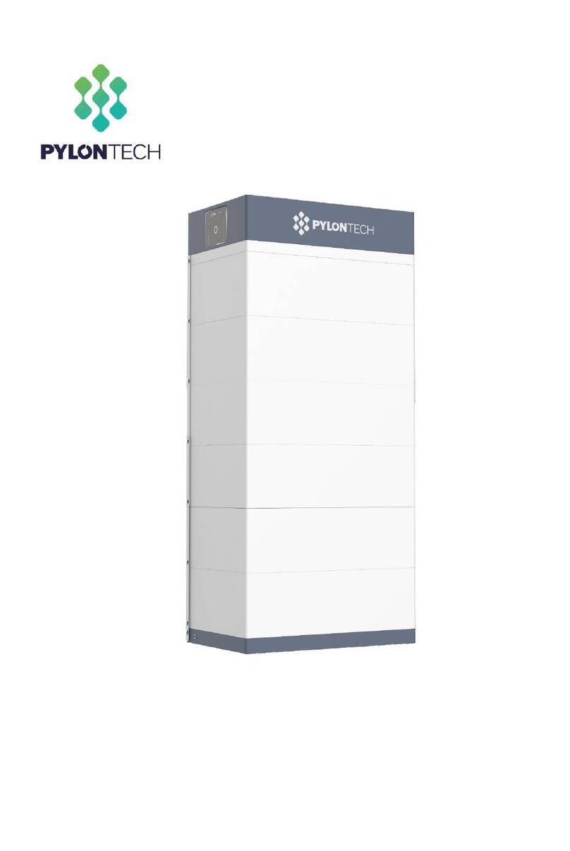
Pylontech PowerCube-X1 User manual

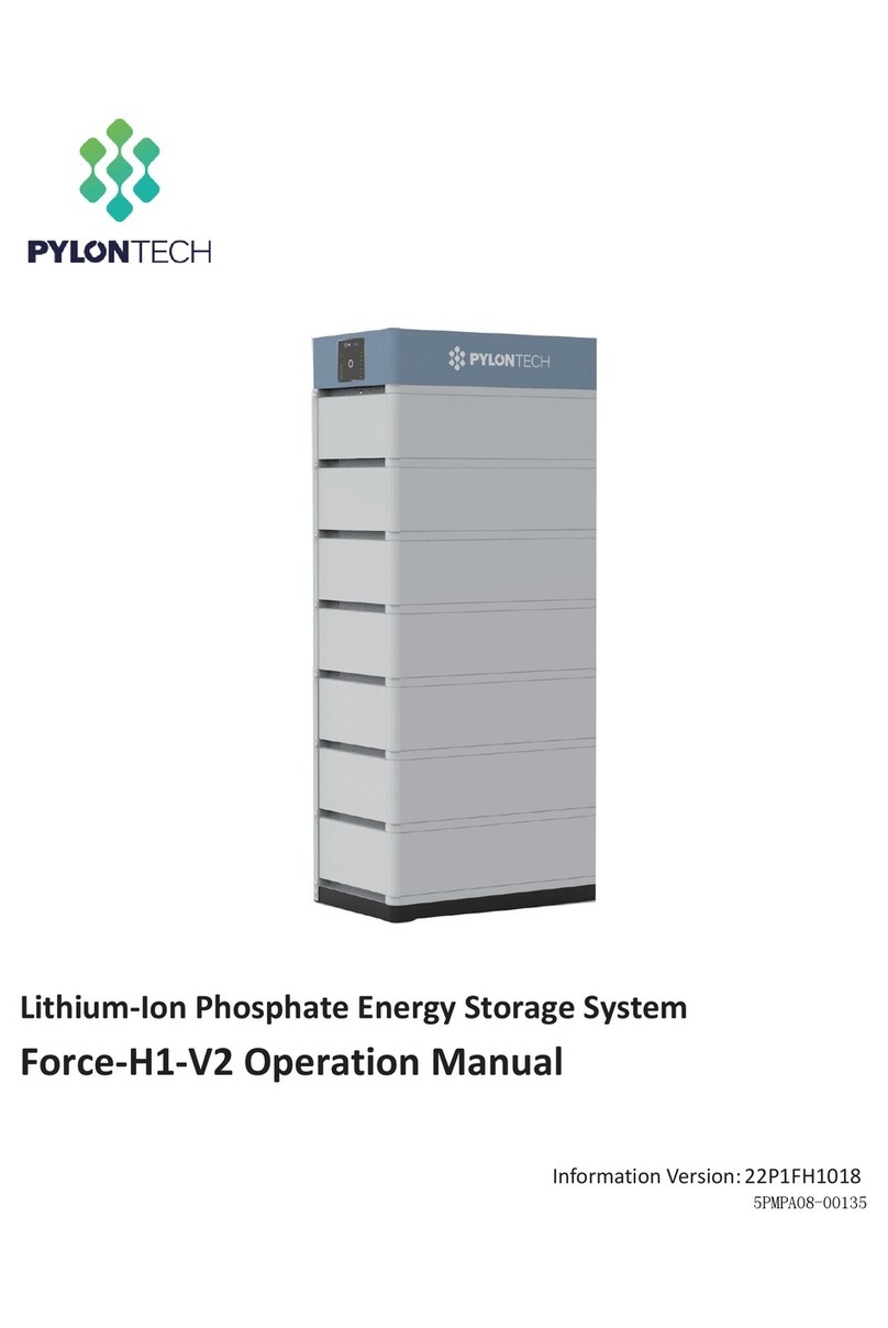
Lithium-Ion Phosphate Energy Storage System
PowerCube-X1 Operation Manual
Information Version: 2.3

This manual introduces PowerCube-X1 from Pylontech. PowerCube-X1 is a high voltage
Lithium-Ion Phosphate Battery storage system. Please read this manual before you install the
battery and follow the instruction carefully during the installation process. Any confusion, please
contact Pylontech immediately for advice and clarification.
Contents
1. SAFETY .............................................................................................................................................1
1.1 Symbol................................................................................................................................... 1
2. SYSTEM INTRODUCE........................................................................................................................ 3
2.1 Product Introduce ............................................................................................................... 3
The parameter of system ............................................................................................................ 4
2.2 System Diagram................................................................................................................... 4
2.2.1 Multi battery string parallel connection by CAN communication between
MBMS and BMS diagram (battery string qty. İ6 set)............................................................ 4
2.2.2 Diagram between BMS and battery modules: ........................................................... 4
3. INSTALLATION ................................................................................................................................. 5
3.1 Tools ....................................................................................................................................... 5
3.2 Safety Gear .......................................................................................................................... 5
3.3 System Working Environments Checking.........................................................................6
3.3.1 Cleaning ............................................................................................................................ 6
3.3.2 Temperature......................................................................................................................6
3.3.3 Cooling System .................................................................................................................6
3.3.4 Heating System .................................................................................................................6
3.3.5 Fire-extinguisher System................................................................................................... 6
3.3.6 Grounding System............................................................................................................ 6
3.4 Package Items..................................................................................................................... 7
Accessories....................................................................................................................................7
Unpacking and check the Packing List:...................................................................................7
3.5 Handling and placement ..................................................................................................9
3.5.1 Handling and placement of the battery module ......................................................9
3.5.2 Handling and placement of the rack...........................................................................9
3.5.3 The fix and installation of the rack.................................................................................9
3.5.4 Control Module (BMS) and all Battery Modules install into the Rack ....................10
3.5.5 Install the MBMS into a 19’ standard rack [On the top of BMS, or use the
rack configured by user]...........................................................................................................10
3.6 Cables connection ...........................................................................................................10
3.6.1 Pay attention terms:.......................................................................................................10
3.6.2 Cables Connection........................................................................................................11
CAN Communication Mode between MBMS and BMS (battery string qty. İ6 set)
(battery string qty. İ6 set).......................................................................................................11
CAN Communication Mode between MBMS and BMS Cable Diagram:........................12
3.6.3 ADD Switch Setting (Address Assignment).................................................................13
Under CAN Communication Mode between MBMS and BMS (battery string qty.
İ6 set) .........................................................................................................................................13
3.6.4 System turns on ...............................................................................................................14
3.6.5 System turns off ...............................................................................................................17
4. SYSTEM DEBUG.............................................................................................................................. 18
5. MAINTENANCE.............................................................................................................................. 19
5.1 Trouble Shooting:...............................................................................................................19
5.2 Replacement of main component..................................................................................21
5.2.1 Replacement of Battery Module................................................................................. 21
5.2.2 Replacement of Control Module (BMS) .................................................................... 22
5.2.3 Replacement of 3rd level Control Module (MBMS).................................................. 22
5.3 Battery Maintenance....................................................................................................... 23
6. STORAGE RECOMMENDATIONS ................................................................................................. 24
7. SHIPMENT ..................................................................................................................................... 24
ANNEX 1: CABLE CONNECTION DIAGRAM ......................................................................................... 25
ANNEX 2: INSTALLATION AND SYSTEM TURN ON PROGRESS LIST........................................................ 26
ANNEX 3: SYSTEM TURN OFF PROGRESS LIST ........................................................................................ 28

1. S
a
The P
o
Read
worki
n
Incorr
e
¾in
j
¾d
a
p
a
Skills
o
Qualif
i
ztr
a
w
zk
n
zk
n
1.1 S
y
Read the product manual before operating the battery system!
t
Dang
e
Dang
e
Warni
n
warra
n
a
fety
o
werCube-
X
all safety
i
n
g on with t
h
e
ct operati
o
j
ury or dea
t
a
mage to
t
a
rty.
o
f Qualified
i
ed person
n
a
ining in th
e
ith hazards
;
n
owledge
o
n
owledge
o
y
mbol
e
r: Batterie
s
circuite
d
e
r: Lethal v
o
may oc
c
n
g: DO N
O
n
ty scope
X
1 is a hig
h
i
nstructions
h
e system.
o
n or work
m
t
h to the o
p
t
he system
Personnel
n
el must ha
v
e
installatio
n
;
o
f this manu
o
f the local
r
Danger
Warning
Caution
s
deliver el
e
d
, or wrongl
y
o
ltages are
c
ur if touch
O
T open or
h
voltage
D
carefully
p
m
ay cause
:
p
erator or a
h
ardware
a
v
e the follo
w
n
and com
al and oth
e
r
egulations
Lethal vo
zBatt
e
cau
s
zOnly
strin
g
Risk of b
a
zDO
N
zDe-
e
ther
e
Risk of b
a
e
ctric pow
e
y
installed.
present in
t
the cables
deform th
e
D
C system,
p
rior to an
y
:
third party;
a
nd other
p
w
ing skills:
missioning
o
e
r related d
and direct
i
ltage!
e
ry strings
w
s
e a lethal
v
qualified
p
g
s.
a
ttery syste
m
N
OT pull ou
t
e
nergize fro
e
is no volta
a
ttery syste
m
e
r, resulting
t
he battery
and termin
e
battery
m
operated
b
y
work an
d
p
roperties b
o
f the elec
t
ocuments;
ves.
w
ill produc
e
v
oltage an
d
p
erson can
m
damage
t
the conn
e
m all multi
p
ge.
m
failure or
in burns or
terminals
a
als.
m
odule, ot
h
b
y skilled/
q
observe t
e
longing t
o
t
rical syste
m
e
high volta
d
an electri
c
perform t
h
or persona
l
ctors while
p
le power
life cycle r
e
a fire haz
a
a
nd cables.
h
erwise the
q
ualified p
e
hem at all
o
the oper
a
m
, as well a
s
a
ge DC po
w
c
shock.
h
e wiring o
f
l
injury
the system
sources a
n
e
duction.
a
rd when t
h
Severe inj
u
product
w
e
rsonnel onl
times wh
e
a
tor or a thi
r
s
the deali
n
w
er and c
a
f
the batte
is operatin
g
d verify th
a
h
ey are sh
o
u
ries or dea
t
w
ill be out
o
y.
e
n
r
d
n
g
a
n
ry
g
!
a
t
o
rt
t
h
o
f
1/ 28
19PIXV0703

Warni
n
Warni
n
Cauti
o
Cauti
o
n
g: Whene
v
such as
r
n
g: Power
C
18ć2
8
low tem
well as. I
t
o
n: Improp
e
o
n: Incorre
c
v
er working
r
ubber glov
C
ube-X1 sys
t
8
ć. Out of t
perature al
t
will affect
e
r settings o
r
c
t inverter p
a
on the ba
t
es, rubber
b
t
em workin
g
he working
arm or pro
the warran
r
maintena
n
a
rameters
w
t
tery, wear
b
oots and
g
g
tempera
t
temperat
u
tection wh
i
ty terms as
n
ce can p
e
w
ill lead to
a
suitable p
e
g
oggles.
t
ure range:
re range
m
i
ch further
l
well.
e
rmanently
a
further fa
u
e
rsonal prot
0ć50ć;
ay cause t
h
l
ead to th
e
d
amage t
h
u
lty/dama
g
t
ective equ
Optimum
t
h
e battery
s
e
cycle life
h
e battery.
g
e to batter
ipment (PP
t
emperatur
e
s
ystem ove
r
reduction
a
r
y.
E)
e
:
r
/
a
s
19PIXV07032/ 28

2. S
y
2.1 P
Powe
r
which
be us
e
espe
c
install
a
The p
a
y
stem Int
r
roduct Intr
o
r
Cube-X1 is
is one of t
h
e
d to supp
o
c
ially suitab
a
tion spac
e
a
rameter of
r
oduce
o
duce
a high volt
a
h
e new ene
r
o
rt reliable
p
le for thos
e
e
, restricted
system
a
ge batter
y
r
gy storage
p
ower for v
a
e
applicati
load-beari
n
y
storage s
y
products
d
arious type
i
on scene
n
g and lon
g
y
stem base
d
d
eveloped
a
s
of equip
m
which req
u
g
cycle life.
d
on lithium
a
nd produ
c
m
ent and s
y
u
ired high
iron phosp
h
c
ed by Pylo
y
stems. Po
w
power o
u
h
ate batte
r
ntech. It c
a
w
erCube-X1
u
tput, limit
e
r
y,
a
n
is
e
d
PowerCube-X1
(336V50AH)
1 Cell Technology Li-ion(LFP)
2 Battery System 16.8
3 Battery System 336
4 Battery System 50
5 Battery Controller
SC500-40/SC0500-100
6 Battery Module H48050
7 Battery Module 7
8 Battery Module 2.4
9 Battery Module 48
10 Battery M odule 50
11 Battery Module Cell 15
12 Battery System 378
13 Battery System 10
14 Battery System 25
15 Battery System 50
16 Battery System 310
17 Battery System 10
18 Battery System 25
19 Battery System 50
20 Efficiency 95%
21 Depth of Discharge 90%(8~98%)
22 Dimension(W* D* H,m 600* 505* 1300
23 Communication RS485\CAN
24 Protection Class IP20
25 Weight (kg) 224.5
26 Operation Life(Years) 10
27 Operation 0~50
28 Storage -20~60
29 Product Certificate TUV, CE
30 Transfer Certificate UN38.3
Other˖
1˅Battery Controller 442* 390* 132
2˅Battery M odule 442* 390* 100
No. Product Type
31
3/ 28
19PIXV0703
Remark: The parameter will be changed when the battery modules in different series
(3~7 pcs battery modules).

2.2 S
y
2.2.1
BMS d
2.2.2
y
stem Diag
Multiple b
a
iagram (b
a
Diagram
b
ram
a
ttery string
a
ttery string
b
etween B
M
parallel c
o
q
ty. İ6 se
t
M
S and batt
e
o
nnection v
i
t
s)
e
ry module
s
i
a CAN co
m
s
:
m
municatio
n
n
between
M
M
BMS and
19PIXV07034/ 28

3. In
Pleas
e
Progr
e
3.1 T
o
The fo
l
A
NOTE
Use p
r
If insu
l
insula
t
3.2 S
It is re
c
Ins
u
stallatio
n
e
check e
v
e
ss List> dur
i
o
ols
l
lowing too
l
Wire C
u
Screw Dri
v
A
djustable
r
operly insul
a
lated tools
t
ed alterna
t
afety Gea
r
c
ommend
e
u
lated glov
n
v
ery install
a
i
ng the inst
a
l
s are requi
r
u
tte
r
v
er Se
t
Wrench
a
ted tools
t
are not a
t
ives, exce
p
e
d to wear
t
es
a
tion step i
n
a
ll.
r
ed to instal
Cr
i
E
l
o prevent
a
vailable, c
o
p
t their tips,
w
he followin
g
Safet
y
n
detail at
l the batter
y
i
mping Mo
d
l
ectric Scre
w
Sleeve P
i
a
ccidental
e
over the
e
w
ith electri
c
g
safety ge
y
goggles
<Annex 2
y
pack:
d
ula
r
Plier
w
Driver
i
ece
e
lectric sh
o
e
ntire expo
s
c
al tape.
ar when d
e
:
Installatio
1
0
o
ck or short
c
s
ed metal
s
e
aling with t
S
a
n and Sys
t
Cable T
0
00VDC M
u
circuits.
surfaces
w
t
he battery
a
fety shoe
s
t
em Turn
O
i
es
ltimete
r
ith availab
pack
s
O
N
le
5/ 28
19PIXV0703

3.3 S
y
3.3.1
The b
a
perfor
Befor
e
clean
Dust
a
If it`s
d
for cl
e
Dang
e
3.3.2
Powe
r
28ć.
Cauti
o
temp
e
3.3.3
It is e
s
range
Cauti
o
temp
e
3.3.4
It is e
s
range
It is ne
Cauti
o
temp
e
3.3.5
The ro
The fir
e
maint
e
3.3.6
Befor
e
reliabl
must
m
The re
s
y
stem Wor
k
Cleaning
a
ttery syste
m
mance of t
e
installatio
n
environme
n
a
nd humidit
y
d
etected th
e
e
aning pur
p
e
r: the pow
e
battery
m
careful t
o
Temperat
u
r
Cube-X1 s
y
o
n: Out of
e
rature alar
Cooling S
y
s
sential to
e
.
o
n: Out of
e
rature alar
Heating S
y
s
sential to
e
. If the envi
r
cessary to
o
o
n: Out of
e
rature alar
Fire-exting
om must b
e
e
system n
e
e
nance re
q
Groundin
g
e
the batte
r
e. If the b
a
m
ake sure t
h
s
istance of
k
ing Enviro
n
m
has high
he system.
n
and syste
n
t. And the
y condition
e
above t
w
p
ose.
e
r cables a
m
odules (b
a
o handle t
h
u
re
y
stem wor
k
the worki
n
m or prote
c
y
stem
e
quip a co
o
the worki
n
m or prote
c
y
stem
e
quip a he
a
r
onment is l
o
o
pen the h
e
the worki
n
m or prote
c
uisher Syst
e
e
equippe
d
e
eds to be
q
uirements
p
g
System
r
y installatio
a
ttery syste
m
h
e groundi
n
the ground
i
n
ments Che
c
voltage c
o
m power
environme
shall be re
g
w
o elements
n
d plugs wi
a
ttery mod
u
h
e Power Pl
u
k
ing tempe
n
g temper
a
c
tion which
o
ling syste
m
n
g temper
a
c
tion which
a
ting syste
m
o
wer than
0
e
ating syst
e
n
g temper
a
c
tion which
e
m
with fire-e
x
r
egularly c
h
p
lease follo
w
n
must ma
k
m
is installe
d
n
g of the c
a
i
ng system
cking
o
nnectors.
T
on, the du
s
nt must ha
v
gularly che
are not in t
ll have hig
h
u
le has acti
u
gs.
rature ran
g
a
ture rang
e
further lea
d
m
to keep
t
a
ture rang
e
further lea
d
m
to keep
t
0
ć, the syst
e
m at first.
a
ture rang
e
further lea
d
x
tinguisher
s
h
ecked to
b
w
local fire
k
e sure the
g
d in an in
d
a
bin is stabl
e
must İ10
0
T
he cleanin
s
t and iron
v
e certain
a
cked durin
g
he working
h
voltage D
C
ve DC po
w
g
e: 0ć50
e
will cau
s
d
to the cy
c
t
he batter
y
e
will cau
s
d
to the cy
c
t
he batter
y
em may b
e
e
will cau
s
d
to the cy
c
s
ystem for s
a
b
e in norm
a
equipmen
t
g
rounding
p
d
ependent
e
and relia
b
0
m¡
g conditio
n
scurf must
a
nti-dust ab
i
g
the syste
m
range, the
C
power fr
o
w
er at termi
n
ć; Optimu
e the bat
t
c
le life redu
c
system in
a
e the bat
t
c
le life redu
c
y
system in
a
e
shut dow
n
e the bat
t
c
le life redu
c
a
fety purpo
a
l condition
t
guidance.
p
oint of the
e
quipment
b
le.
n
will affect
be remov
e
ility.
m
continuo
u
system sha
l
o
m serial c
o
n
al all the ti
m
u
m temper
a
t
ery syste
m
ction.
a relevant
t
ery syste
m
ction.
a relevant
n
for protec
t
t
ery syste
m
ction.
o
se.
n
. Refer to t
h
basement
cabin (e.
g
the isolati
o
e
d to keep
u
s operatio
l
l be stopp
e
nnected
m
e), must
b
a
ture: 18ć
m
over / lo
w
temperatu
r
m
over / lo
w
temperatu
r
t
ion purpos
e
m
over / lo
w
h
e using a
n
is stable a
n
g
. containe
r
o
n
a
n.
e
d
b
e
w
r
e
w
r
e
e
.
w
n
d
n
d
r
),
19PIXV07036/ 28

3.4 Package Items
Accessories
The type and quantity of the accessories are subject to the battery packing list.
NOTE
Power cable uses water-proofed connectors. It must keep pressing this Lock
Button during pulling out the power plug.
Unpacking and check the Packing List:
Power Cable + (Battery Module
and Main Controller Serial
Connection)
Orange/0.16m/4AWG/2 Orange
Surlok Terminal pcs 1
Power Cable - (Battery Module and
Main Controller Serial Connection)
Black/2m/4AWG/2 Black Surlok
Terminal pcs 1
Power Cable (Battery Module
Upper and Lower Serial
Connection)
Orange/0.18m/4AWG/1 Orange &
1 Black Surlok Terminal pcs 14
Battery Cascade
Communication Cable (0.18m)
Black/0.18m/8 Core Super 5th
Class Twisted-pair Wire/RJ45 pcs 15
160
2000
180
7/ 28
19PIXV0703

External Battery CAN
Communication Cable (direct)
Black/3.5m/Super 5th Class
Twisted-pair Wire/2 RJ45 terminal pcs 1
External Power Cable + Orange/2m/4AWG/SURLOK
Terminal/25-8 Terminal pcs 1
External Power Cable - Black/2m/4AWG/SURLOK
Terminal/25-8 Terminal pcs 1
2000
2000
19PIXV07038/ 28
For SC0500-40S control module:
External Power Cable -/+ Black-Red/2m/10AWG/HRS-DF60/G
T6-6 Terminal pcs 1

3.5
H
Warni
n
Warni
n
3.5.1
Sigle
b
with it
.
3.5.2
If with
o
3.5.3
The ra
Batter
y
Batter
y
H
andling an
n
g: The bat
t
n
g: Power
C
personn
e
Handling
a
b
attery mo
d
.
Handling
a
o
ut handlin
The fix an
d
ck must be
y
rack bas
e
y
rack wall
d placeme
t
ery rack is
I
C
ube-X1 is
a
e
l only.
a
nd place
m
d
ule is 24k
g
a
nd place
m
g tools mus
d
installatio
n
fixed install
e
ment hole
s
fixed holes
nt
I
P00. It mus
t
a
high volt
m
ent of the
b
g
. If without
m
ent of the r
a
t
have mor
e
n
of the rac
k
ed on the
b
s
bitmap (u
n
bitmap (u
n
t
be installe
d
age DC s
y
b
attery mo
d
t
handling
t
a
ck
e
than 4 m
e
k
b
asement and arrange
n
it: mm):
Front si
d
n
it: mm):
d
in a restri
c
y
stem, ope
r
d
ule
t
ools must
h
e
n to handl
i
d
e
c
ted acces
s
r
ated by q
u
h
ave more
i
ng with it.
on the wall
s
area;
ualified an
d
than 1 ma
with M10 s
c
d
authoriz
e
nto handli
n
c
rews.
e
d
n
g
9/ 28
19PIXV0703

3.5.4
zIn
a
n
zIn
3.5.5
user]
zIn
zIn
3.6
C
3.6.1
Dang
e
Dang
e
Dang
e
Cauti
o
Groun
The P
o
the m
o
uses n
Rack
G
If ther
e
the b
o
frame
groun
d
If wan
base.
Control M
o
stall the bu
c
n
d all batt
e
stall the co
n
Install the
M
stall the bu
c
stall the M
B
C
ables con
n
Attention:
e
r: The batt
e
is stable
e
r: All the pl
to black
e
r: No shor
t
port.
o
n: Wrong
c
ding
o
werCube-
X
o
dule’s surf
a
ormal rack
,
G
rounding:
e
is a groun
o
ttom of th
e
of the con
t
d
ing.
t connect
t
Grounding
o
dule (BMS
)
c
kle nuts. T
h
e
ry modules
n
trol modul
M
BMS into
a
c
kle nuts. T
h
B
MS in. Uses
n
ection
e
ry system i
and reliabl
e
ugs and so
c
. Otherwise
t
circuit or
r
c
ommunic
a
X
1 module
s
a
ce and ra
,
it should r
e
ding metal
e
containe
r
,
t
ainer. The
n
t
he ground
cable mus
t
and all Ba
t
h
e position
o
.
e
(BMS) an
d
a
19’ stand
a
h
e position
o
4screws t
o
s
high volt
a
e
.
c
kets of th
e
it will caus
e
r
eserved c
o
tion cables
s
’ groundin
g
ck’s surfac
e
e
move the
p
frame outs
i
,
the fix hol
e
n
through th
cable, it c
a
t
ı10AWG
t
tery Modul
e
o
f nuts mus
t
d
all batter
y
a
rd rack [O
n
of nuts mus
o
fix.
a
ge DC syst
e
e
power ca
b
e
personal i
n
o
nnection
o
s
connectio
g
is based
o
e
. So it don
`
p
aint at th
e
i
de the rac
k
e
of the fix f
r
h
e groundin
a
n be con
n
.
e
s install in
t
t
meet the
p
y
modules i
n
n
the top of
t meet the
e
m. Must
m
b
les must b
e
n
jury.
o
f the batt
e
n will caus
e
o
n metal di
`
t need gro
correspon
d
k
, for exam
p
r
ame can
b
g of the co
n
ected to t
h
o the Rack
p
osition of t
n
. Each mo
d
BMS, or us
e
p
osition of
t
m
ake sure th
e
from oran
e
ry system’
s
e
the batter
y
rectly touc
h
u
nding ca
b
d
ing groun
d
p
le, the me
b
e fixed dir
e
n
tainer to
e
h
e M8 grou
n
t
he control
m
d
ule uses 4
e
the rack
c
t
he MBMS.
h
e groundin
ge to oran
g
s
positive
a
y
system fa
i
h between
b
les at all. If
d
ing point.
tal angle st
e
ctly with t
h
e
nsure relia
b
nding bolt
o
m
odule (B
M
screws to f
i
onfigured
b
g of the ra
c
g
e and bla
c
a
nd negati
v
i
lure.
eel frame
a
h
e metal
b
le
o
n the fra
m
M
S)
i
x.
b
y
c
k
c
k
v
e
a
t
m
e
19PIXV070310 / 28

3.6.2
Note:
Lock
B
If ther
e
which
CAN
When
uses
C
of 1st
P
Cables C
o
Power ca
b
B
utton durin
e
are mor
e
aggregat
e
Communi
c
system co
n
C
AN casca
d
P
owerCube
o
nnection
b
le uses wa
t
g pulling o
u
e
than 1 ra
c
e
informatio
c
ation Mod
e
n
figured P
o
d
e commu
n
-X1 uses C
A
G
t
e
r
-proofed
u
t the pow
e
c
k of Pow
e
n from all t
h
e
between
M
werCube-
X
n
ication mo
A
N commu
n
G
rounding B
connecto
r
e
r plug.
er
Cube-X1,
h
e BMS an
d
M
BMS and
B
X
1İ6 sets.
T
o
de. The co
m
n
ication m
o
olt
r
s. It must k
e
there will r
e
d
communi
c
B
MS (batter
y
T
he comm
u
m
municati
o
o
de.
e
ep pressin
e
quire a M
c
ate with in
v
y
string qty.
u
nication b
e
o
n betwee
n
n
g this
M
BMS on th
e
v
erter/PCS.
.
İ6 sets)
e
tween Po
w
n
the MBMS
e
top
w
erCube-X
and the B
M
Fi
x
h
1s
M
S
x
Hole
4
11 / 28
19PIXV0703

CAN
C
Note:
T
C
ommunic
a
T
he 1
st
Pow
e
a
tion Mode
e
rCube-X1
between
M
should be i
n
M
BMS and B
M
n
stalled ne
a
M
S Cable
D
a
rest to the
D
iagram:
MBMS.
19PIXV070312 / 28

13 / 28
19PIXV0703
3.6.3 ADD Switch Setting (Address Assignment)
ADD Switch BMS is a 6 bit dial switches to manually distribute the
communication address of the battery system. Nether position is OFF,
means “0”. Upper position is ON, means “1”. 1
st
bit to 5
th
bit is for
address, and the 6
th
bit dial switch support a 120 ¡resistance
(Terminal Resistance).
ADD Switch MBMS is a 6 bit dial switches to manually distribute the
communication address of the battery system. Nether position is OFF,
means “0”. Upper position is ON, means “1”. 1st bit to 4th bit is for
address, the 5th and the 6th bit dial switch support a 120¡resistance
(Terminal Resistance).
3.6.3.1 Under communication for single BMS (battery string qty. 1 set)
The BMS’s first five bits must set in below <BMS’s Address Configure Table>. The last BMS’s terminal
resistance must set in “1” (X=1);
The address is configured follow ASCII code: (“X” is terminal resistance).
BMS’s Address Configure Table:
3.6.3.2 Under CAN Communication Mode between MBMS and BMS (battery string qty. İ6 set)
The BMS’s first five bits must set in below <BMS’s Address Configure
Table>. The last BMS’s terminal resistance must set in “1” (X=1), and
other BMS’s terminal resistance must set in “0”.
The address is configured follow ASCII code: (“X” is terminal
resistance).
BMS’s Address Configure Table:
The MBMS’s ADD Switch set with “000011”. The last 2 bits are terminal
resistances.
Note: the 1
st
to 4
th
bit dial for MBMS refer to 3.6.3.3
&$1 0 RGEXV $GGUHVVGLDOE LW
;
;
;
;
;
;
;
Battery
String Address Bit
1 10000X
2 01000X
3 11000X
4 00100X
5 10100X
6 01100X

3.6.4
Doubl
e
PCS is
OFF.
Warni
n
Syste
m
(1) S
w
w
o
(2) Tu
r
T
h
Fr
o
System tur
n
e
check al
l
same leve
l
n
g: MBMS
m
m
turns on s
t
w
itch the e
x
o
rk normall
y
r
n on the 1s
t
h
e second
B
o
m 1st BMS
n
s on
l the powe
r
l
with the b
m
ust be turn
t
ep:
x
ternal pow
y
.
t
BMS (Batt
e
B
MS must b
e
to the last
B
r
cables a
n
attery syst
e
ed on afte
r
er
or invert
e
e
ry Control
M
e
operated
B
MS Then tu
n
d commu
n
e
m. Check
a
r
all battery
e
r/PCS on
M
odules) o
f
after the fi
r
rn on the b
n
ication ca
b
a
ll the pow
strings self-
c
, to make
s
f
battery str
i
r
st battery s
attery strin
g
b
les. Make
e
r switch o
f
c
heck finis
h
s
ure all the
i
ng:
t
ring’s self-
c
g
s on one b
y
sure the v
o
f
every bat
t
h
.
power eq
u
c
heck is su
c
y one.
o
ltage of t
h
t
ery system
u
ipments c
a
c
cessful.
h
e
is
a
n
19PIXV070314 / 28
3.6.3.3 Multi MBMS Communication Mode
In some project it configures multi Energy Storage Systems. In
this case will have multi MBMS. The address of MBMS must follow
<MBMS’s Address Configure Table>

zTurn on t
h
h
e “POWER SWITCH”:
P
O
W
E
R
S
W
I
T
C
H
:
15 / 28
19PIXV0703
Caution: The time interval between every time switch OFF/ON the “Power Switch” shall >3
minutes.
Caution: When the breaker is tripped off because of over current or short circuit, must wait
after
30min to turn on it again, otherwise may cause the breaker damage.
zTurn on the “Start Button”:
Press and hold the Start Button for more than
5sec until the buzzer rings, the LED indicator on front panel will light on if the start-
up is successful;
zSystem start process:
The battery string’
s system will check itself, if work normal the battery string system will go
to self-check mode.
If the BMS and all battery modules are working normally, every status LED will lighting
green, that’s mean self-check are pass. Self-check will be finish within 10sec.
If long press the start button within 30s, theಯ
STATUS” lamp will flash red, it is to remind that
the black start function is forbidden within 30s.
If the BMS can’t receive communication from upper equipment because of
the
communication is off, the “STATUS” lamp will light red after 30sec. That doesn’
t means
failure existed, it means this battery string is OK while the external communication is off.

19PIXV070316 / 28
Warning: If has failure during the self-check, must debug the failure then can start next step.
If the “STATUS” lamp shows red from beginning, it means there has some failure in the
battery string, the Power Relays in BMS will open, must debug at first.
Note: The LED lamp will be off in 20sec without any operation.
Caution: During first time power on, the system will require to do fully charge progress for SOC
calibration purpose.
Caution: The whole Battery Energy Storage System (BESS) after installation or restart the system
when long time not in using should charge it to full at first. There will be a regularly (3 month) fully
charge requesting during continuous operation as well, it will be handled automatically
by the communication between BESS and external device.
zBlack-start function:
The system’s relay can be closed by pressing the start button 5s.
And it is necessary to press the start button of the BMS which is connected with MBMS
when you want to use black-start function.
Warning: if the black-start function is used, the terminal of DC “+” and DC “-” will be electricity
dangerous with high DC voltage output.
(3) Switch the MBMS on after all the BMS turn on successful:
Caution: During first time power on, the system will require to do fully charge progress for SOC
calibration purpose.
Caution: The whole Battery Energy Storage System (BESS) after installation or restart the system
when long time not in using should charge it to full at first. There will be a regularly (3
month) fully charge requesting during continuous operation as well, it will be handled
automatically by the communication between BESS and external device.
And check whether MBMS is working. The “STATUS” lamp will light green.
When the voltage difference between strings is smaller than the parameter, the battery string will do
the parallel operation. Then the power relays in BMS will switch ON after 30 seconds.The “STATUS” lamp
of the BMS will light green; When the voltage difference between strings is bigger than the parameter,
the battery string will NOT do the parallel operation, the “STATUS” lamp of the BMS will light red, but it is
normal; Such battery string will be paralleled in during chargingstage automatically.
Note: If the MBMS can’t build communication with other equipment, the system can’t work normally.
External device should communicate with battery system through LAN, CAN or RS485. Otherwise maybe
cause battery system work abnormal.

3.6.5
When
(1) S
o
(2) T
u
str
i
s
w
tr
a
(3) Tu
r
(4) Tu
r
System tur
n
failure or b
e
o
ft-off the
P
u
rn off the
s
i
ng (Power
C
w
itch of P
C
a
nsmission t
h
r
n off the “
P
r
n off the
“
n
s off
e
fore servi
c
P
CS throug
h
s
witch bet
w
C
ube-X1),
o
C
S, to ma
h
rough bat
t
P
ower Swit
c
“
Power Swi
t
c
e, must tur
n
h
PCS’s con
t
w
een PCS a
n
o
r turn off
t
ke sure n
t
ery string a
c
h” of the B
M
t
ch” of the
n
the batte
r
t
rol panel.
n
d battery
t
he power
o current
nd PCS.
M
S.
MBMS. If t
r
y storage s
y
he ESS co
n
y
stem off:
n
figures onl
y
y
single battery witho
u
u
t
M
B
(5) Tu
r
Th
e
of
f
Cauti
o
batte
r
time t
o
NOTE
After i
n
www.
p
B
MS, then i
g
r
n off the U
P
e
UPS can
t
f
the UPS to
o
n: Before
c
r
y same vol
o
do the b
a
n
stallation,
p
ylontech.
c
g
nore this
P
S if config
u
t
urn on if h
a
save its po
w
c
hange th
e
tage to th
e
a
lance for t
h
DO NOT for
g
c
om.cn/ser
v
o
peration s
u
red.
a
ve equipm
w
er.
e
battery
m
e
other in s
y
h
is replace
d
g
et to regis
t
v
ice/suppo
r
tep.
m
ent must k
e
m
odule for
s
y
stem batt
e
d
battery m
t
er online f
o
rt
e
ep runnin
g
s
ervice, mu
e
ry module
odule.
o
r full warra
n
g
can’t turn
st charge/
d
s
. Otherwis
e
n
ty:
off. Other
w
d
ischarge
t
e
the syste
m
w
ise must tu
r
he replac
e
m
need lo
n
r
n
e
d
n
g
17/ 28
19PIXV0703
Other manuals for PowerCube-X1
3
Table of contents
Other Pylontech Storage manuals

Pylontech
Pylontech PowerCube-H1-V2 User manual

Pylontech
Pylontech PowerCube-M1-C User manual

Pylontech
Pylontech PowerCube-X1 User manual

Pylontech
Pylontech PowerCube-M2 User manual

Pylontech
Pylontech PowerCube-M1 User manual

Pylontech
Pylontech Force-H2-V2 User manual

Pylontech
Pylontech Force-H1 User manual

Pylontech
Pylontech Force-L2 User manual

Pylontech
Pylontech PowerCube-X1 User manual

Pylontech
Pylontech Force-H3 User manual