pyromation 28-02700-J User manual

Thermocouple Thermometer Models
28-02700-J (Type J)
28-02700-K (Type K)
28-02700-T (Type T)
5211Industrial Road
FortWayne,IndianaU.S.A.46825
(260)484-2580
(260)482-6805(Fax)
A-1299-0680
Edition05
OPERATING MANUAL

CERTIFICATE OF
CONFORMANCE
This thermometer was calibrated using
equipment traceable to the National Institute
ofStandardsandTechnology(NIST).
Thisinstrument conforms to
NISTmonograph175 revisedto
ITS-90.
The accuracy of the thermometer at the time
ofcalibrationwas within specificationsstated
intheoperatingmanual.
ModelNo.:_________________________
SerialNumber:______________________
Dateplacedinservice:________________
Topurchase an NIST certificate of traceability
withtestdata andtestdateformeterandprobe,
pleasecontact yourdealer or:
PYROMATION
5211Industrial Road
FortWayne,IndianaU.S.A.46825
260-484-2580

1
INTRODUCTION
Thisversatilehand-heldinstrument provideshighly
accuratetemperature measurements. The instru-
ment is designed for easy operation and includes
thefollowingfeatures:
• Operator selectionof Celsiusor Fahrenheit scale
• Resolution of 0.1° from–99.9 to 299.9°
• Four-digit LCD
• Hold feature for temporarily retaining areading
• Field calibrationcapability
• Low battery warning
• Built-in tilt stand for easy hands-freeoperation
• Two blade female ANSI mini-connectorinput
• Operates with a wide selection of probes

2
SAFETY PRECAUTIONS
THIS INSTRUMENT IS
DESIGNED TO ACCEPT
LOW LEVEL SIGNALS SUPPLIED BY STAN-
DARD THERMOCOUPLES. UNDER NO CIR-
CUMSTANCES SHOULDTHE INPUTVOLTAGE
EXCEEDTHE SPECIFIED 50V RMS.
DO NOT USE OR STORE
THIS INSTRUMENT IN
MICROWAVE OVENS OR ANY ABNORMALLY
HOT OR COLD AREAS.
WEAKBATTERIES SHOULD
NOT BE LEFT IN THE IN-
STRUMENT. DEADBATTERIES CAN LEAKAND
CAUSE DAMAGETO UNIT.
VOLTAGES PRESENT AT
THETHERMOCOUPLEMAY
ALSO BE PRESENT AT THE BATTERY TERMI-
NALS. ALWAYS DISCONNECT THE THERMO-
COUPLEWHEN CHANGING BATTERIES.
TO PREVENT IGNITION OF
A HAZARDOUS ATMOS-
PHERE,BATTERIESMUSTONLYBECHANGED
INAN AREA KNOWNTOBENON-HAZARDOUS.
AFIN DE PREVENIR
L'INFLAMMATION
D'ATMOSPHERES DANGEREUSES, NE
CHANGER LES BATTERIES QUE DANS DES
EMPLACEMENTS DESIGNES NON DAN-
GEREUX.
TOPREVENT IGNITION OF
A HAZARDOUS ATMOS-
PHERE BY ELECTROSTATIC DISCHARGE,
CLEANWITH DAMP CLOTH.
WARNING
WARNING
CAUTION
CAUTION
WARNING
DANGER
AVERTISSEMENT

3
SPECIFICATIONS
THERMOCOUPLE PROBES
Type Temperature Range
Type J: –200°C to 1000°C (–328°F to 1832°F )
Type K: –250°C to 1372°C(–418°F to 2501°F)
TypeT: –250°Cto 400°C(–418°F to 752°F)
Out of range display: - - - -
Resolution: 0.1°/1° autoranging, 0.1° from
–99.9°to299.9°, 1° outside this range.
Accuracy
> –99.9°: +(0.2%ofreading +0.5°C)
+(0.2% of reading+0.9°F)
< –99.9°: +(0.25%ofreading, +1°C)
+(0.25%ofreading +2°F)
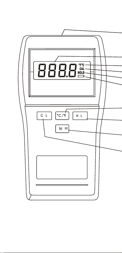
Display:4-digitLCD with 0.5 in high numerals.
Display update rate: 0.6 sec per update.
Input: Onethermocouple withANSIconnector.
Input Protection: 50V rms
Battery: Two AA, 1.5V alkaline ANSI-L40,
IEC-LR6.
Battery Life: 750hours continuous,typical.
Low battery indication
Battery Symbol on when 8 to 10 hours of
batteryliferemains.
Batterysymbolblinking:replace battery
Operating Conditions
Stated accuracy: 18°C to 28°C (64°F to 82°F)
Useful range: 0°C to 40°C (32°F to 104°F)
Storage: –40°C to 65°C (–40°F to 149°F)
Humidity(non-condensing):10%to90%

4
Dimensions
3 cm D x 8.4 cm W x 15.8 cm H
(1.2 in x 3.3 in x 6.2 in)
Weight with batteries: 227 grams (8 ounces)
Ingress protection: MeetsIEC-529 IP-54 fordust
andwater-resistantenclosures.
Intrinsic safety
Thisproductisenergy limitedforintrinsicallysafe
operationin hydrogenatmospheres per Class I,
Division 1, Groups A, B, C and D hazardous
(classified)locations forUL per UL913andCSA
per C22.2 No. 0-M1982 and No. 157-M1987.
Maximumsurfacetemperature:135°C(T4);UL
fileNo.E182612 (1997).
Compliance: (For CE Mark)
EN61326-1/A1:1998(EU EMC Directive)

5
BATTERY INSTALLATION AND
REPLACEMENT
WEAKBATTERIES SHOULD
NOT BE LEFT IN THE
INSTRUMENT. DEAD BATTERIES CAN LEAK
AND CAUSE DAMAGETO UNIT.
VOLTAGES PRESENT AT
THETHERMOCOUPLEMAY
ALSO BE PRESENT AT THE BATTERY TERMI-
NALS. ALWAYS DISCONNECT THE THERMO-
COUPLEWHEN CHANGING BATTERIES.
TO PREVENT IGNITION OF
A HAZARDOUS ATMOS-
PHERE,BATTERIESMUSTONLYBECHANGED
INAN AREA KNOWNTOBENON-HAZARDOUS.
AFIN DE PREVENIR
L'INFLAMMATION
D'ATMOSPHERES DANGEREUSES, NE
CHANGER LES BATTERIES QUE DANS DES
EMPLACEMENTS DESIGNES NON DAN-
GEREUX.
CAUTION
DANGER
WARNING
AVERTISSEMENT

6
If battery indicator turns on, battery life is approxi-
mately8 to 10 hours.Thebatteryindicator will start
blinkingwith less than 1 hour of liferemaining.
ATTHISPOINT,BATTERYMUST BE CHANGED.
IF BATTERY VOLTAGE GOES TOO LOW, DIS-
PLAY WILL GO BLANK.
SeeSPECIFICATIONS forbattery type.
1. Beforechanging battery, turninstrument offand
disconnectthermocouple.
2. Loosen screw and lift battery cover off back of
case.
3. Removethe two AA batteries.
4. Insert twonewbatteries observing polarity.
5. Install cover and tighten screw.

7
CONNECTING A THERMOCOUPLE
Usethecorrect thermocoupletypeforyourinstru-
ment. Using an incorrect thermocouple type will
result in erroneous readings. Thermocouples are
colorcodedbytypeusing theNorthAmerican ANSI
ColorCode as follows:
TYPE COLOR
J Black
K Yellow
T Blue
Thermocoupleconnectorshaveonewidebladeand
onenarrowblade.
Donot forceconnector in back-
wards.
Connectthermocouple to receptacle at top
ofinstrument as showninthefollowingillustration.
Thermocouple wiring polarity must be correct. If
readings decrease as the temperature increases,
thethermocouple wires maybereversed. The red
wire is negative for thermocouple wires manufac-
turedin NorthAmerica.

8

9

10
2. Ifathermocoupleis not connected or if the ther-
mocouple is defective, the display will indicate
OPEn.
3. Select °C or °F by pressing the°C/°F key.Tem-
peraturescale can be switchedat anytime. The
thermometer remembers the lastselectedscale
the next time you turn the power on.
4. For optimum instrument accuracy, allow one
minuteforambient temperaturestabilization. If
theunithas been stored at an extremeambient
condition,moretime will be needed.
Thermocouples are sensitiveat the tip or measur-
ing junction. When taking temperature measure-
ments,allow time forthe readingto stabilize. Mul-
tiplyingthetime constant of the probe by5willgive
youthe approximatetime required.
Notethatthe readings will automatically change to
1°resolutionbelow–99.9° orabove299.9°.
If desired, press the HOLD key to retain the read-
ing on the display.Press HOLD key again for nor-
maloperation.
If the display shows "- - - -" the temperature read-
ing is out of range of the instrument.
OPERATION
Note: Be sure the thermocouple you are using
matchestheinstrument setting indicated on the
unit.
1. Press the ON/OFF key.The thermometer per-
forms a self-test and all display digits and indi-
cators, as shown below, should remain on for
approximatelytwoseconds.

11
FIELD CALIBRATION
Thethermometerisfactorycalibratedanddoesnot
require calibration before use.The CAL function
allowssinglepointcalibrationofthethermometer,
at0°C(32°F)to compensate forthermocouple off-
seterror.It is notnecessarytoperform a field cali-
brationto obtain specified meter accuracy.Use the
field calibration feature to improve thermometer/
probeaccuracy ortocompensateforthermocouple
drift.
1. Follow steps 1 through 4 in OPERATION sec-
tion.
2. Packsensing end of probe in a container tightly
packed with crushed ice and filled with distilled
water.Allow temperature to stabilize.
3. Press and hold the CAL key for 5 seconds to
enterthe calibrationmode,the CALannunciator
on thedisplaystarts blinking. Release the CAL
key.
4. If the measured temperature is from −10°C to
10°C (14 to 50°F), when the temperature read-
ing is stable, press theCAL key.
TheCAL indicatorwillstopblinkingandthe read-
ing will be set to 0°C (32°F).The CAL indicator
will remain turned on, indicating a field calibra-
tion is active.
If“Err”isdisplayed,either the displayedreading is
outsidethe abovelimits or the batteries are weak.
CANCELING A FIELD CALIBRATION
1. Turn thethermometer off.
2. Hold the CAL key down while pressing the
ON/OFF key.
Thefieldcalibrationis canceled and the thermom-
eter reverts to the default factory calibration. The
CALannunciatorisnowturned off.

12
FIELD CALIBRATION LOCKOUT
AND RE-ENABLE
The calibration lockout feature, prevents any field
calibrationchanges. Thelockoutremains in effect
untilalockoutre-enablehasbeenperformed. Use
thefollowingproceduresto lockoutorre-enablethe
fieldcalibrationoperation.
Lockout Procedure
1. Turn thethermometer off.
2. Simultaneously press andhold the CALand the
°C/°Fkeysdownandmomentarilypressthe ON/
OFF key. Continue to hold the CAL and °C/°F
keys for at least 5 seconds.
Re-Enable Procedure
1. Turn thethermometer off.
2. Simultaneously press and hold the HOLD and
the CAL keysdownandmomentarily press the
ON/OFF key. Continue to hold the HOLD and
CAL keys until the display blanks.

13
MAINTENANCE
Properly used, the thermometer should maintain
calibrationindefinitelyandnotrequire serviceother
thanoccasionalcleaningof thehousingand chang-
ingofthe batteries.
CLEANING
TOPREVENTIGNITIONOF
A HAZARDOUS ATMO-
SPHERE BY ELECTROSTATIC DISCHARGE,
CLEANWITH DAMP CLOTH.
Do not clean with abrasives or solvents.Use mild
detergents,neverimmersenor useexcessivefluid.
BATTERIES
If there is no display when the thermometer is
turned on, check condition of the twoAA batteries.
Alsocheck thatthebatteryterminals arecleanand
batteries are properly installed. If replacement is
necessary, referto the BATTERYINSTALLATION
AND REPLACEMENT section for replacement
procedure.
WARNING

14
SERVICE
SUBSTITUTION OF COM-
PONENTS MAY IMPAIR
INTRINSICSAFETY.
LA SUBSTITUTION DE
COMPOSANTSPEUT COM-
PROMETTRELA SECURITE INTRINSEQUE.
There are no internal adjustments or user
replaceableparts.
If “Err” followed by the numbers 1 through 9 is
displayed (see example below) return unit for
service. Note that “Err”alone may be displayed
during improper field calibration.
A-1925-32
Rev. E
Printed in U.S.A.
050798
Note:Serial number label is located inside
batterycompartment.
WARNING
AVERTISSEMENT

15

WARRANTY
TheManufacturer warrantsthisproduct to be free
fromsignificant deviationsfrom publishedspecifi-
cations. Ifrepair or adjustment is necessarywithin
thewarrantyperiod, the problemwill be corrected
at no charge if it is not due to misuse or abuse on
yourpart as determined by the Manufacturer. Re-
pair costs outside the warranty period, or those
resulting from product misuse or abuse, may be
invoicedtoyou.
The warranty period for this product is noted
on theWarranty Card.
PRODUCT RETURN
To limit charges and delays, contact the seller or
Manufacturerforauthorizationandshipping instruc-
tions before returning the product, either within or
outsideof the warrantyperiod. Whenreturning the
product,please state the reason forthe return. For
your protection, pack the product carefully and in-
sureitagainstpossibledamage or loss. Anydam-
ages resulting from improper packaging are your
responsibility.
TECHNICAL ASSISTANCE
Ifyouhaveanyquestionsabouttheuse ofthis prod-
uct,contactthe Manufactureror authorizedseller.
Trademarks bearing the ® symbol in this publication are
registered in the U.S. and in other countries.
A-3477-57
Rev. E
Printed in U.S.A.
051000
This manual suits for next models
2
Table of contents