W&T Electronics 57713 User manual

W&T
Manual
Web-Thermometer
Web-Thermo-Hygrometer
Web-Thermo-Hygrobarometer
Web-Thermometer Relay
Web-Thermometer Air Quality
Typ 10/100BaseT, 12-24V
Modell 57713, 57714, 57715
57716, 57718, 57720
Release 1.03, Mar 2016

W&T
© 03/2016 by Wiesemann und Theis GmbH
Microsoft, MS-DOS, Windows, Winsock and Visual Basic
are registered trademarks of the Microsoft Corporation
Subject to errors and changes:
Since we can make mistakes, none of our statements should
be used without checking. Please let us know of any mistakes
or misunderstandings you are aware of, so that we can reco-
gnize and eliminate them quickly.
Perform work on and with W&T products only as described
here and only if you have read and understood the manual
fully. Unauthorized use can result in hazards. We are not liab-
le for the consequences of unauthorized use. When in doubt,
check with us or consult your dealer!

W&T
Introduction
The W&T Web-Thermometer contains all functions in a box
to measure, store and display your climate data. Moreover,
the numerous alarm functions are available which can be in-
tegrated into your own applications or into available systems.
In this manual you find all information which you need for the
installation, configuration and the use of the Web-Thermome-
ter.

W&T
Content
Introduction................................................................... 3
1 Quick-Start/Commissioning........................................ 7
1.1 Connecting the sensor (#57713, #57714, #57715,
#57718, #57720) ............................................................7
1.2 Connecting the PT100/PT1000 sensor and output confi-
guration (#57616) ...........................................................8
2 Online measurement storage inside the W&T Cloud . 14
2.1 Auto connect ................................................................14
2.2 Create a user account ...................................................14
2.3 Assign data by 4-digit access code in the cloud ............15
2.4 Assign measured data via user account in the device ....15
3.1 Configuring network parameters with WuTility ..... 16
3.1.1 Applications and prerequisites...................................16
3.2 Assigning the IP using DHCP protocol ................... 19
3.2.1 Manual activation of DHCP.........................................19
3.2.2 System name .............................................................20
3.2.3 Lease time .................................................................20
3.3 Assigning the IP using the ARP command.............. 21
3.4 Assigning the IP using the serial port.................... 23
4 Supply voltage .......................................................... 25
4.1 Power over Ethernet......................................................25
4.2 External supply.............................................................25
5 Ethernet interface ..................................................... 26
5.1 Link status....................................................................26
5.2 10/100BaseT on RJ45 ...................................................26

5
W&T
6 Connecting the sensor .............................................. 27
6.1 NTC sensor measuring input (#57714)..........................27
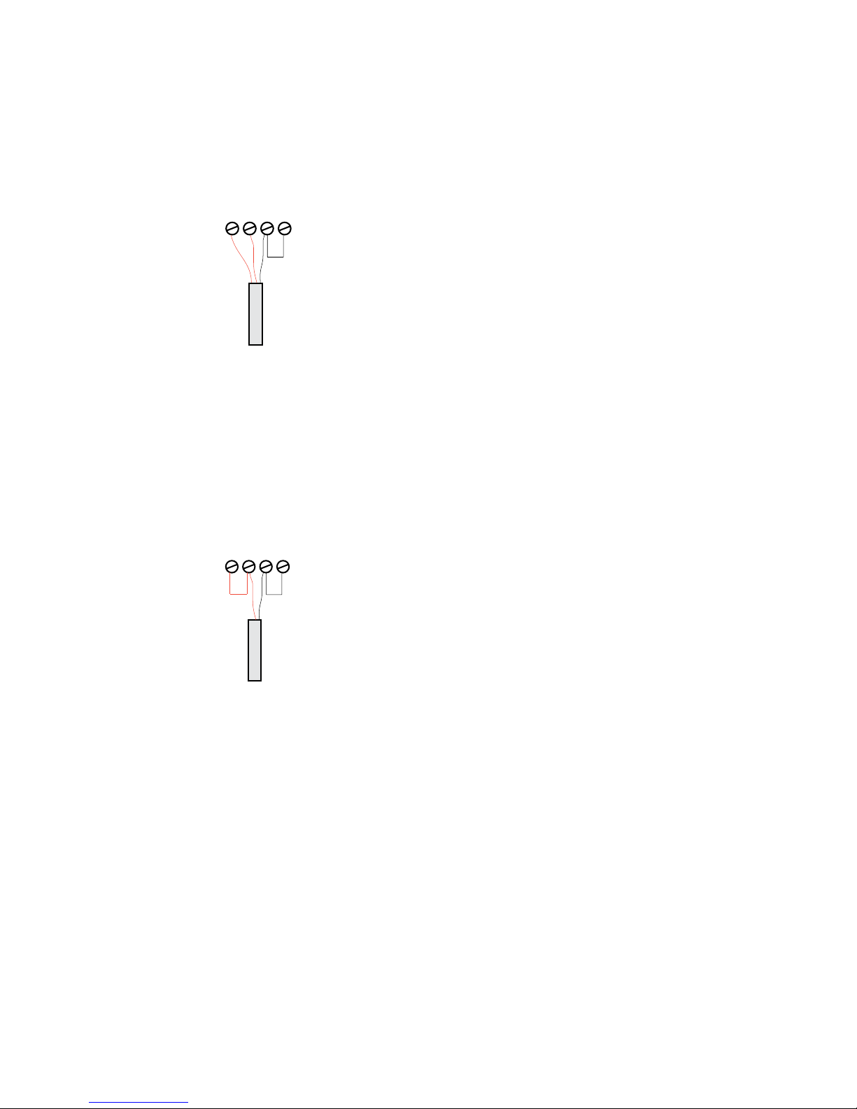
6.2 Pt100/1000 sensor measuring input (#57715)..............27
6.3 Combined sensor measuring input (#57713, #57720) ..27
7 Configuration Using Web-Based Management ........... 29
7.1 Home............................................................................29
7.2 Visualization.................................................................30
7.3 Own webpage ...............................................................31
7.4 Login ............................................................................31
8 Basic Settings............................................................ 33
8.1 Network........................................................................33
8.2 Sensors.........................................................................34
8.3 Date/Time ....................................................................34
8.4 Language/Infos.............................................................34
8.5 Data storage .................................................................35
8.6 Password ......................................................................35
9 Communication paths ............................................... 36
9.1 Web pages ....................................................................36
9.2 Mail ..............................................................................39
9.3 Cloud............................................................................39
9.4 RSS ...............................................................................39
9.5 SNMP/Syslog.................................................................39
9.6 FTP ...............................................................................40
9.7 Socket access ...............................................................40
10 Alarms/Messages ................................................... 41
11 Diagnosis................................................................ 43
12 Device information ................................................. 44
13 Maintenance............................................................ 45
13.1 LED Test .....................................................................45
13.2 Reboot........................................................................45
13.3 Factory defaults ..........................................................45
13.4 Save configuration ......................................................46
13.5 Restore configuration .................................................46

6
W&T
14 Individual request of measurement values............. 47
14.1 Request via TCP/IP......................................................47
14.2 Requesting via UDP.....................................................48
14.3 Requesting via SNMP...................................................49
15 Firmware Update..................................................... 52
15.1 Where is the latest firmware available? ........................52
15.2 Firmware update over the network under Windows .....52
16 Hardware-Reset to factory defaults ........................ 54
17 Technical data......................................................... 55
17.1 Technical data for the articles 57714 and 57715 ........55
17.2 Technical data for the articles 57713 and 57720 ........56
17.3 Technical data for the article 57716............................57
17.4 Technical data for the article 57718............................58
18 Disposal ........................................................................59

7
W&T
1 Quick-Start/Commissioning
Just a few steps are required to start up your W&T Web-Ther-
mometer and to make it visible in your network.
Power-over-Ethernet
The Web-Thermometers are designed for use in PoE (Power-
over-Ethernet) environments in accordance with IEEE802.3af.
Power is provided by the network infrastructure using the
RJ45 terminal. The devices support both phantom power
using data pairs as well as power feed using the unused wire
pairs s. Power Supply).
!Use of the Web-Thermometer is also possible in networks
without PoE power supply. In this case simply use an
external power supply attached to the screw terminal as
described in the chapter Power Supply. No additional configu-
rations or settings are necessary.
1.1 Connecting the sensor (#57713, #57714, #57715,
#57718, #57720)

8
W&T
Plug the sensor included in the scope of delivery into the
9-pin IO terminal on the unit.
Information for Web-Thermometer Air Quality, #57718:
!
The measuring of the VOC value begins after an initiali-
zation time of 15 minutes after powering on the device.
In this time a VOC value of 450ppm will be displayed.
1.2 Connecting the PT100/PT1000 sensor and output
configuration (#57616)
The output of the Web-Thermograph Relay is switched inter-
nally using a relay contact (normally open). The consumer
is connected to the screw terminals 1 and 2. The maximum
switchable DC or AC voltage is 39V, with a maximum current
flow of 300mA.
The PT100 or PT1000 temperature sensor is connected to
screw terminals 3, 4, 5 and 6, whereby the wires of the same
color must lie adjacent to each other.

9
W&T
The incoming line to the PT100 4-wire sensor may be of vir-
tually any practical length.
Connecting a PT100 3-wire sensor:
When connecting a PT100 3-wire sensor the same-color wires
are connected to the terminals marked with the correspon-
ding colors. A jumper to the remaining free terminal is re-
quired for the single wire.
Connecting a PT100 2-wire sensor:
When connecting a PT100 2-wire sensor, one wire is brought
to the red terminal and the other to the black terminal. Jum-
pers must be placed here to the free terminals.

10
W&T
1.3 Ethernet connection (#57713, #57714, #57715,
#57716, #57718, #57720)
The Web-Thermometer incorporates an IEEE802.3-compatible
network interface on a shielded RJ45 connector. The pin as-
signments correspond to an MDI port, so that the connection
to the hub or switch is accomplished using a 1:1 shielded
patch cable.
1.4 LED-displays
Power Status
Error
Power-LED
OFF: There is no power present. Check the correct connec-
tion of the supply (PoE or the external power supply)
ON: Power is present (PoE or the external power supply).

11
W&T
Power Status
Error
Status-LED
Rapid continuous flashing = bootup, no IP
Rapid continuous flashing (approx. 3x/s) indicates that
the device is in the bootup phase and/or has not yet been
assigned an IP address. Please use WuTility for example to
assign the device an IP address.
Slow continuous flashing = connection
Periodic flashing indicates that the port has a valid con-
nection to another network station. After the IP configura-
tion you can open the homepage of the device with a web
browser.
Power Status
Error
Error-LED
The Error-LED shows errors of the device.
All LEDs on = Self-test error
The self-test performed after each start or reset of the
device could not be correctly finished. This error can occur
when you have prematurely broken off a software update
and the full operating software could not be transferred.
The device is no longer capable of being operated in this
condition. Repeat the software update over the network
(see Firmware update), and address the device using its
assigned IP address. If this does not eliminate the error or
should the error occur irrespective of any prior software
update, please return the unit to W&T for service.

12
W&T
Speed Link/Activity
Speed (yellow)
OFF: Simultaneous illumination/flashing of the Link/Acti-
vity LED means there is a link to a device at a rate of 10
MBit/s (10BaseT).
ON: Simultaneous illumination/flashing of the Link/Acti-
vity LED means there is a link to a device at a rate of 100
MBit/s (100BaseT).
Speed Link/Activity
Link/Activity (green)
OFF: The device is not detecting a Link pulse from a hub
or switch. Check the cable or the hub port.
ON: The device has a valid link to a hub or switch. The
Speed LED indicates the data rate in this case.
Flashing: The device is receiving or sending network pak-
kets.
Additional LEDs (internal: #57713, #57714, #57715,
#57718, 57720, external: #57716)
■ on error http://xxx.xxx.xxx.xxx/diag -LED: Indicates inter-
nal configuration errors. For troubleshooting, please open
the page http://xxx.xxx.xxx.xxx/diag in the device.
■system error: Serious hardware error. Attempt to start the
device up again by interrupting supply voltage. If the con-
dition persists, please return the unit for inspection.
!If the Web-Thermometer has no IP address or
Address 0.0.0.0, the on error and system error LEDs
remain on! The system error LED flashes 3x after a brief
time. The LEDs do not turn off until an IP address has been

13
W&T
assigned.

14
W&T
2 Online measurement storage inside the W&T Cloud
With the cloud service W&T offers a comprehensive solution
that enables the backup of data in online storage in addition
to the long-term documentation of temperature and humidity
measurement data in the internal data logger. The measure-
ment data will be sent directly from the measuring point to
the cloud, and is available online.
2.1 Auto connect
The cloud functionality is enabled by default on delivery. If
the device receives its network parameters via DHCP, or you
allow the device Internet access by entering the network para-
meters, it immediately begins the transmission of the collec-
ted values in the cloud.
The measuring data is first not assigned to a user account
and will be stored in an enclosed part of the cloud until
further use.
2.2 Create a user account
To personalize the measurement data, first a user account for
the cloud access must be created. To do this, go to the cloud
homepage
http://cloud.wut.de
and click on „create user account“.
After entering your e-mail address and a password you will
get access to the cloud.

15
W&T
2.3 Assign data by 4-digit access code in the cloud
Log in with your user account to http://cloud.wut.de and
enter the access code included with the device. The collected
data are now associated with your account and are available
for you immediately.
Alternative:
2.4 Assign measured data via user account in the device
After you have created a cloud user account, open the confi-
guration menu of your device and login as admin user. Navi-
gate to the page
Communication Paths -> Cloud
and enter your user data for the cloud access. After clicking
on the button „Bind“ all measurement data of this device,
from this moment, is stored into your user account.
By clicking on the button „Unbind“ the allocation of the data
from this moment is separated and no further values will be
stored in your account.
Click again on „Bind“ and a new series of measurements is
created in the cloud for your user account that contains all
the unassigned values of the sensor.
!
For further information about the service of the Cloud
functions you find instructions on http://cloud. wut. de

16
W&T
3.1 Configuring network parameters with WuTility
WuTility is the central inventorying and management tool for
all W&T network devices. In addition to convenient assigning
of the IP parameters, WuTility also provides quick access to
device configurations, the ability to perform firmware up-
dates, managing configuration profiles, etc.
WuTility can be directly installed from the included product
CD. Current versions are always available on our website at
http://www.wut.de. From there you can navigate using the
menu tree on the left side.
Downloads rWeb-GraphrSoftware-Tools
After extracting the ZIP file you install WuTility by double-
clicking on the file wutility_***.msi. Start WuTility using
Start rAll Programs rW&T Software Toolkit rWuTility
3.1.1 Applications and prerequisites
IP assignment using WuTility works regardless of the current
network parameters of the device and the computer used.
This means that even if the device does not have IP parame-
ters consistent with the respective network, WuTility can be
used to overwrite them. Likewise, WuTility can be used to
assign any values not consistent with the network the PC is
located in.
• The PC and device must be located in the same physical
network. This means you cannot assign values through a
router.
• Any firewalls and network security packages installed on
the PC must allow communication between WuTility and
the device based on UDP broadcasts. If necessary these
must be correspondingly configured or temporarily turned
off.

17
W&T
• If the device does not have its factory default settings and
there is a system password assigned, this must be known
in order to make changes using WuTility.
Step 1: Start the assignment dialog
WuTility automatically searches the local network for connec-
ted W&T network devices and creates an inventory list. This
search process can be repeated manually as often as desired
by clicking on the Scan button:
Within the inventory list you can identify the desired de-
vice based on its MAC address. For initial installations its IP
address is 0.0.0.0.
Select the device and click on the IP address button:

18
W&T
Step 2: Assign the IP parameters
The Static option allows you to assign fixed basic parameters
while simultaneously disabling the DHCP protocol in the de-
vice. Enter the desired values for IP address, subnet mask and
gateway address in the corresponding entry fields. The DHCP
option enables DHCP protocol in the device, and operation
with a static IP address is no longer possible (see IP Assign-
ment using DHCP Protocol for detailed information).
Clicking on the Next button assigns the network parameters
to the device. After acknowledging the resulting message, all
the columns in the WuTility device list are filled in with infor-
mation.
If necessary, the remaining configuration of the device is done
using Web-Based-Management. Click on the Browser button.
Browser:
Additional information can be found in the section Configura-
tion Accesses for the Web-Thermometer.

19
W&T
3.2 Assigning the IP using DHCP protocol
DHCP protocol is activated by the factory default settings, so
that in network environments dynamic IP assignment is suf-
ficient for connecting the device to the network. The following
parameters can be assigned using DHCP:
• IP address
• Subnet mask
• Gateway address
• DNS-Server
3.2.1 Manual activation of DHCP
To prevent unintended address assignments or address chan-
ges, DHCP protocol is automatically deactivated when using
all other methods for assigning the IP parameters. The follo-
wing methods are then available for later activation of DHCP.
• Management-Tool WuTility
Select the desired device from the device list and click on
the IP Address button. In the following dialog check the
option DHCP and then click on Next.
• WBM configuration
In the menu branch Basic settings r Network r TCP/IP
Settings you can activate DHCP protocol.
1A set static IP address is deleted after DHCP is
activated and the associated automatic reset. The device
automatically sets this to 0.0.0.0 and starts sending DHCP
requests.

20
W&T
3.2.2 System name
To support any automatic updating of the DNS system by
the DHCP server, the device identifies itself within the DHCP
protocol with its system name. The factory default setting
for this is WEBIO- followed by the last three places of the
Ethernet address. For example the factory set system name of
a device with the Ethernet address 00:c0:3d:01:02:03 is WE-
BIO-010203. The system name of the device can be changed
in the configuration. For additional information refer to the
section Menu: Basic Settings r Language/Infos.
3.2.3 Lease time
The lease time determined and transmitted by the DHCP
server specifies the Time-To-Live of the assigned IP address.
After half the lease time has expired, the device attempts to
extend the time for the assigned DHCP server and up update
the address. If this is not possible by the time the lease time
expires, for example because the DHCP server can no longer
be reached, the device deletes the IP address and starts a new
cyclical search for alternate DHCP servers for the purpose of
assigning a new IP address.
Because of the absent clock, the lease time associated with
the current IP address is no longer available after a reset.
After the restart therefore a corresponding update request is
issued with the original DHCP server. If the latter is not resol-
vable at this point in time, the device deletes the IP address
and starts a new cyclical search for alternate DHCP servers.
If DHCP is activated, the remaining lease time together with
the current IP address is displayed in the menu item device
Information using the format hh:mm:ss.
This manual suits for next models
5
Table of contents