Q-FREE MD 5850 MultiReader User manual

MD 5850 Installation Manual
Dokument tittel: Installation Manual for MD 5850 MultiReader
Dokument nummer: 645-054-1999
Filnavn/Path: Arkiv/…/645-054-1999.doc
Revisjon nummer: 1 2 3 4
Forfattet/revidert dato: 06.09.99 29.10.99 15.06.00 01.08.01
Forfattet/revidert av: ES ES STo FV
Sjekket av: STo STo ES STo
Godkjent dato: 21.09.99 29.10.99 15.06.00 01.08.01
Godkjent av: STo STo STo STo
Revisjonshistorie
Rev.2: Han-Modular connector pos. C pin 9 and 11 signals exchanged to correspond with I/O Filter Schematic.
Rev.3: Changed pflash instruction for serial flashing.
Rev.4: MVME168P preparations and flashing added.
Q-Free®ASA 645-054-1999 rev.4 0 of 20

MD 5850 Installation Manual
Installation Manual
for
MD 5850 MultiReader
This equipment complies with part 15 of the FCC rules. Any changes or
modifications not expressly approved by the manufacturer could void the
user's authority to operate the equipment.
Q-Free®ASA 645-054-1999 rev.4 1 of 20

MD 5850 Installation Manual
Table of Content
1INTRODUCTION ..............................................................................................................4
1.1 Abbreviations..........................................................................................................................4
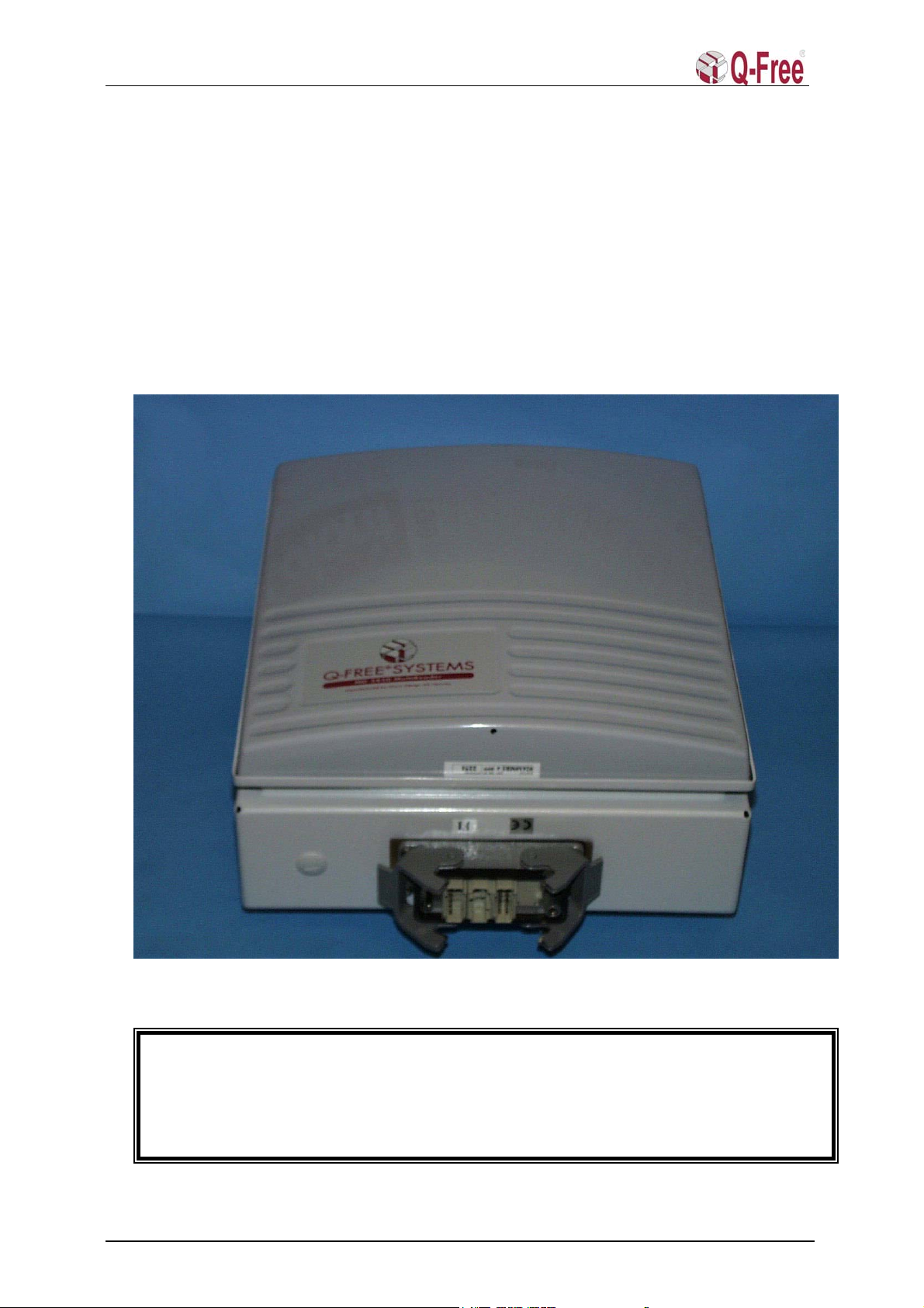
2MULTIREADER HARDWARE INSTALLATION..........................................................4
2.1 MultiReader Cabinet Installation .........................................................................................4
2.2 Installation site .....................................................................................................................5
2.2.1 Toll plaza superstructure................................................................................................................. 5
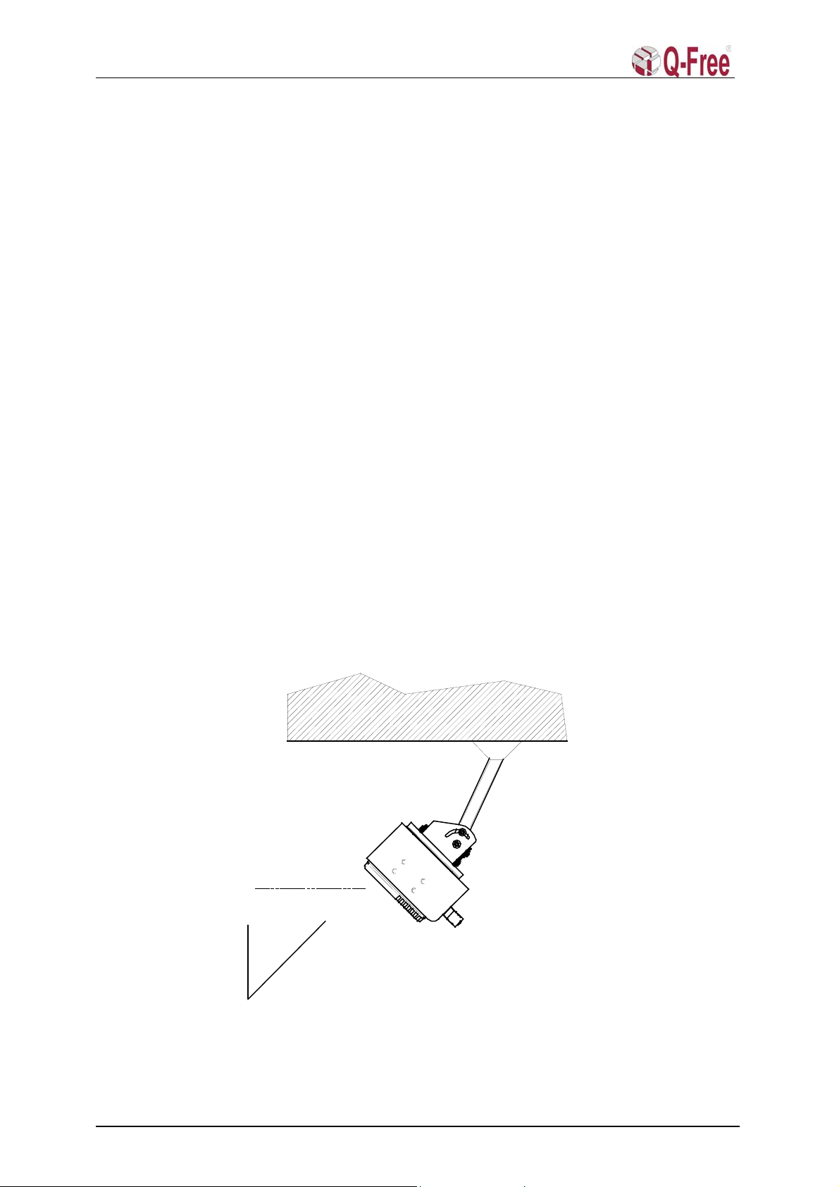
2.3 Basic installation ..................................................................................................................5
2.3.1 Mounting height and angle ............................................................................................................. 5
2.4 Square tube from customers construction........................................................ 6
2.4.1 Requirements for using the Uni-bracket ......................................................................................... 6
2.4.2 Fixing the square tube..................................................................................................................... 6
2.4.3 Square tube angles .......................................................................................................................... 6
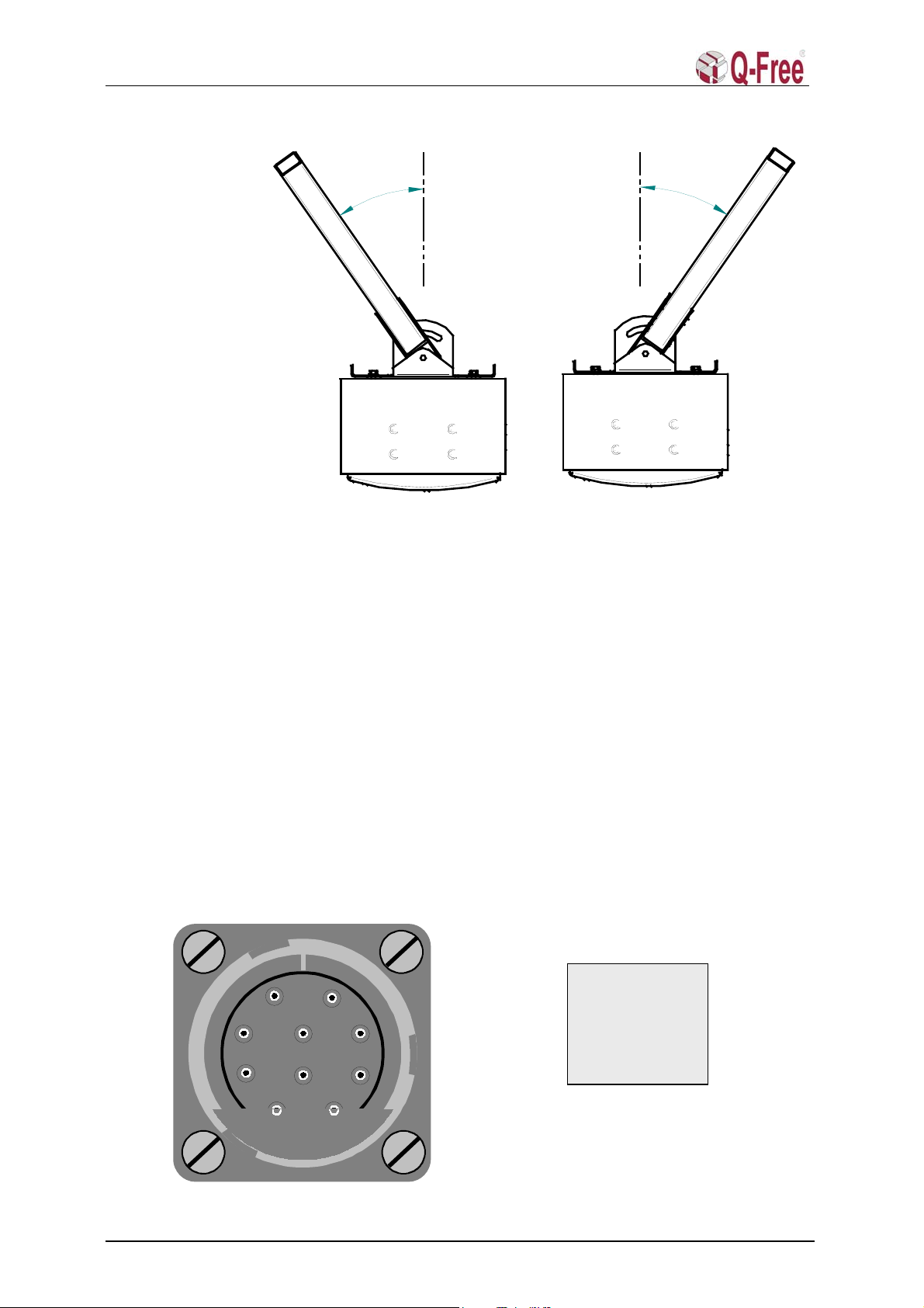
2.5 Square tube sideways angles.................................................................................................. 6
3MULTIREADER CABLE INTERFACE..........................................................................7
3.1 MultiReader Power Supply and Data Interface ..................................................................7
3.2 Circular Chassis Connector................................................................................................... 7
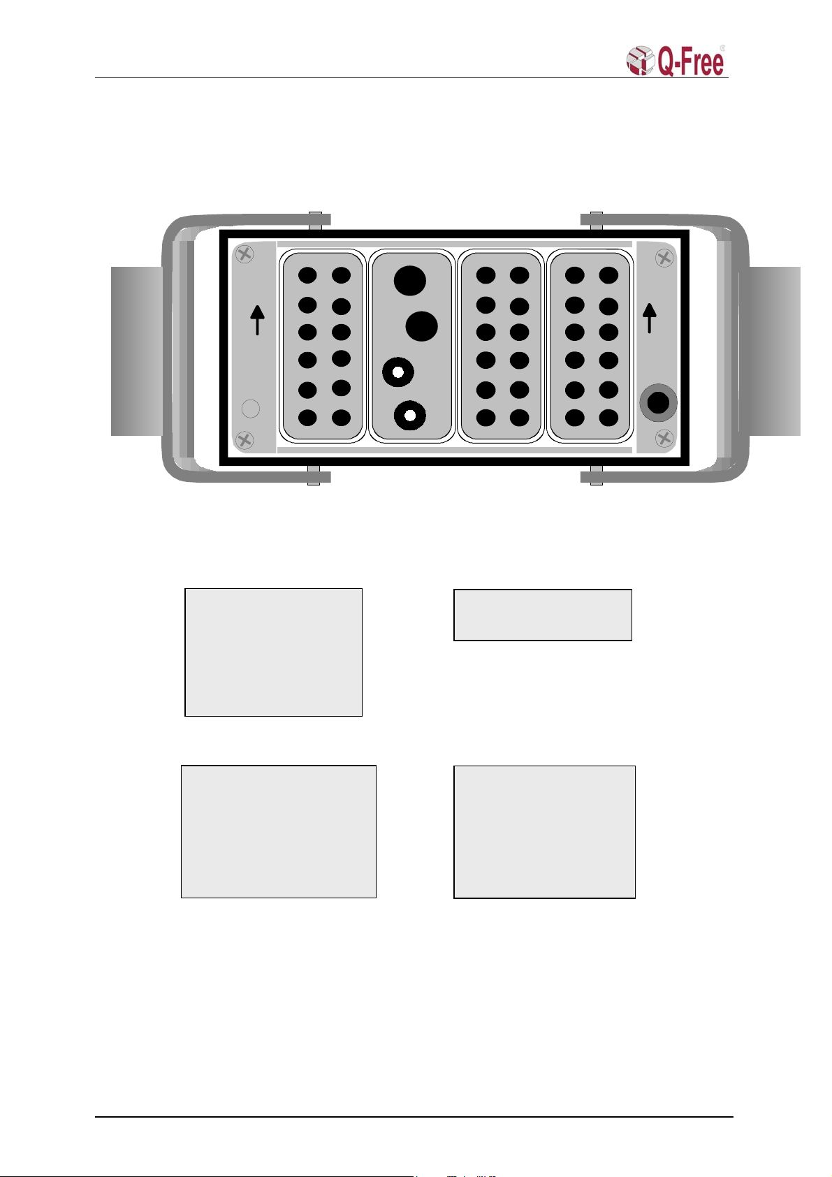
3.3 Han-Modular Connector .......................................................................................................8
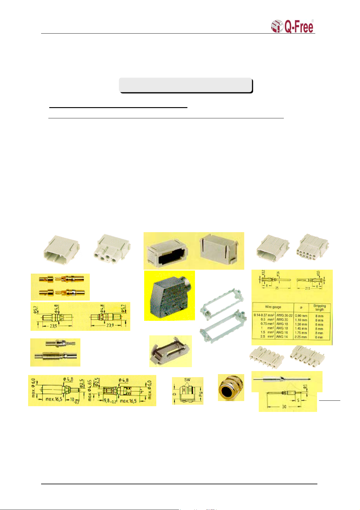
3.4 Han-Modular connector assembly parts ..............................................................................9
3.5 Installation tools (preferred) ...............................................................................................10
4EXTERNAL CABLE INTERFACE................................................................................11
4.1 Cable dimensions.................................................................................................................. 11
4.2 Circular connector ...............................................................................................................11
4.3 Han-Modular connector ...................................................................................................... 12
5MULTIREADER SOFTWARE INSTALLATION.........................................................12
5.1 How to flash the MV162-12 and MVME162P CPU-card through the serial port
(console)............................................................................................................................................12
5.1.1 Loading the software and flashing................................................................................................ 13
5.1.2 Closing up..................................................................................................................................... 14
5.1.3 Make new startup file ................................................................................................................... 15
5.1.4 bootChange................................................................................................................................... 15
5.2 How to flash the MultiReader via Ethernet. ......................................................................15
6TEST WITH APPLICATION SW ...................................................................................16
6.1 PC/ Terminal Connection to MultiReader......................................................................... 16
6.2 PC/ Terminal connection to MultiReader through a TPC ............................................... 16
6.3 Testmode ...............................................................................................................................17
6.4 Format ...................................................................................................................................17
7TEST WITH TEST TAGS AND INSTRUMENTS.........................................................18
7.1 Downlink signal test .............................................................................................................18
7.1.1 Test Tag measurements. ............................................................................................................... 18
7.1.2 Measuring the MultiReader footprint with a test tag. ................................................................... 18
7.1.3 Spectrum Analyser measurement. ................................................................................................ 19
Q-Free®ASA 645-054-1999 rev.4 2 of 20

MD 5850 Installation Manual
7.1.4 The spectrum analyser settings should be:.................................................................................... 19
7.1.5 Measurement of the MultiReader footprint with a Spectrum Analyser. ....................................... 19
7.2 Uplink signal test ..................................................................................................................20
7.2.1 MultiReader without level detection.............................................................................................20
7.2.2 MultiReader with level detection.................................................................................................. 20
8APPENDIX A ...................................................................................................................20
Q-Free®ASA 645-054-1999 rev.4 3 of 20

MD 5850 Installation Manual
1 INTRODUCTION
1.1 Abbreviations
CPU Central Processing Unit
LED Light Emitting Diode
LHC Left Hand Circular.
MR MultiReader
OBU On Board Unit
RF Radio frequency. In this document RF means microwave frequencies in the 5.8 GHz
band.
RX Receiver/Receive signal
TPC Toll Plaza Computer
TX Transmitter/Transmit signal
2 MULTIREADER HARDWARE INSTALLATION
2.1 MultiReader Cabinet Installation
The Q-FREEMultiReader (MD 5850) has two connector options, 10-pin circular and Han-
Modular connector.
Four M8x40 screws at the rear of the cabinet make it easy to design a mechanical interface to
gantries, walls, bridges, etc.
An optional Universal mounting bracket may be delivered as shown in fig.2.1.1.
This chapter is a guide to the mechanical and wiring installation of the MD 5850 MultiReader.
The instructions in this manual are based upon the use of the stainless steel 2-piece universal
bracket made by MD, MD part no. 11000013. This bracket is not included in the MD 5850, and
must be ordered separately.
Heat Protection Shield
Mounting Bracket
Fig.2.1.1 Optional Universal-Mounting bracket for MD 5850.
Q-Free can on request provide a special designed mounting bracket. The bracket is made of stainless
steal and allows the MultiReader to be adjusted both sideways and vertically for maximum Flexibility.
Q-Free®ASA 645-054-1999 rev.4 4 of 20

MD 5850 Installation Manual
2.2 Installation site
2.2.1Toll plaza superstructure
The normal configuration at toll plaza with separate lanes, is to have the MR installed hanging
from the toll plaza superstructure. Mounting the MR under the superstructure also provides
protection from rain, snow, sun heat radiation etc.
In some cases, a gantry or pole will be more suitable for mounting the MR, but then there is no
protection from, rain, snow, sun heat radiation etc.
2.3 Basic installation
2.3.1Mounting height and angle
The normal mounting height is 5.5 to 6m above the road, and the normal mounting angle is 45°
down from vertical (fig.2.3.1). Optimum performance is obtained when the MultiReader (MR)
is mounted above the middle of the lane.
If the centre of the antenna lobe must correspond with the centre of a magnetic loop, it is
preferred that magnetic loop is installed in a position, which gives a normal MultiReader angle.
In vehicle access control systems with physical barrier where the magnetic loop vehicle
detection and OBU transactions has to be matched, the optimum-mounting angle could be
between 25°and 45°relative to the vertical plane through the MR. It is not recommended to
have a mounting angle (pointing angle) below 25°because then it is possible that overhanging
roof of special vehicles could shadow the tag.
An angle below 45°will reduce the communication zone length. This must be considered when
the vehicles are passing at a high speed.
5.5- 6.0mabove l ane sur f ace
45°
Figure 2.3.1 Side view of MR mounted hanging from concrete superstructure
Q-Free®ASA 645-054-1999 rev.4 5 of 20

MD 5850 Installation Manual
2.4 Square tube from customers construction
2.4.1Requirements for using the Uni-bracket
The bracket accepts 2x2" or 50x50mm square tube. The customer must obtain the square tube
and fix it to the suitable superstructure, gantry or pole. At the end of the square tube, there must
be drilled holes with 11mm diameter for the bolts that fix the Uni-bracket to the tube.
Ø11mm
50mmspaci ng
cl ose t o edge t o avoi d conf l i ct
Figure 2.4.1 Square tube construction
2.4.2Fixing the square tube
The customer should assure that the square tube is rigidly fixed and will not sway or yaw in
wind and will not deflect from original position over time.
2.4.3Square tube angles
The square tube can be mounted in different angles, from vertical to horizontal in the
longitudinal axis of the lane. The Uni-bracket is fixed to the MR with 4 M8 bolts that are in a
200mm square pattern. The bracket can therefore be inverted on the MR in order to accept
different angles of the square tube.
2.5 Square tube sideways angles
The Uni-bracket also provides for sideways adjustment.
Q-Free®ASA 645-054-1999 rev.4 6 of 20

MD 5850 Installation Manual
3
5
°
3
5
°
Figure 2.5.1 Top view of MR, showing sideways adjusting range
3 MULTIREADER CABLE INTERFACE
3.1 MultiReader Power Supply and Data Interface
The cable interface to the MultiReader is dependent on which option and version that is
delivered. 24VDC, with 48VDC and 12VDC as options can power the MultiReader.
The normal data interface is as follows:
Circular connector:
RS422 (RS232)
Han-Modular connector:
RS422 combined with twisted pair, optical or coaxial Ethernet.
Information on how and where the different signals are located in the interface connectors is
given below (Fig. 3.2.1 and 3.3.1).
3.2 Circular Chassis Connector
Signal configuration for the standard 10 pin circular Chassis Connector with bayonet lock
A
B
C
D
E
F
G
H
I
J
POWER SUPPLY &
PIN B +VDC
PIN A +VDC
PIN C -VDC
PIN D -VDC
PIN E -RX
PIN F +RX
PIN G -TX
PIN H +TX
PIN I +VDC
PIN J -VDC
Fig.3.2.1 Circular Chassis Connector pin configuration.
Q-Free®ASA 645-054-1999 rev.4 7 of 20

MD 5850 Installation Manual
3.3 Han-Modular Connector
POS.b POS.c
POS. d
POS.a
THIS SIDE
TOWARDS MULTIREADER ANTENNA
1
2
3
4
1
2
3
4
5
6
7
8
9
11
12
10
1
2
3
4
5
6
7
8
9
11
12
10
ad
HAN DD MODULE MALE
HAN DD MODULE MALE
HAN MULTICONTACT
MODU LE MALE
FRAME FOR
HOUSING
HOUSING
DUMMY MODUL E
FRONT VIEW
CONTACT MALE
FOR HAN DD ADAPTER
CONTACT MALE
FOR HAN DD ADAPTER
POS.d
1
2
3
4
5
6
7
8
9
11
12
10
HAN DD MODULE MALE
CONTACT MALE
FOR HAN DD ADAPTER
POS. a POWER
PIN 2 +48 VDC Option
PIN 1 +48 VDC Option
PIN 3 +48 VDC Option
PIN 4 +12 VDC Option
PIN 5 +12 VDC Option
PIN 6 +12 VDC Option
PIN 7 +24 VDC Standard
PIN 8 +24 VDC Standard
PIN 9 +24 VDC Standard
PIN 10 - IVDC Standard
PIN 11 - IVDC Standard
PIN 12 - IVDC Standard
POS. b FIBRE OPTIC & COAXIAL Eth.net
PIN 2 RX FIBRE
PIN 1 TX FIBRE
PIN 3 TX/RX COAXIAL 1
PIN 4 TX/RX COAXIAL 2
POS. c RS232/RS422/Eth.net twisted pair
PIN 2 +IETX (Eth.net tw. pair)
PIN 1 +IERX (Eth.net tw. pair)
PIN 3 ITXD (RS232)
PIN 4 +ITX (RS422)
PIN 5 NC
PIN 6 +IRX (RS422)
PIN 7 - IERX (Eth.net tw. pair)
PIN 8 - IETX (Eth.net tw ). pair
PIN 9 IRSGND (RS232)
PIN 10 - ITX (RS422)
PIN 11 IRXD (RS232)
PIN 12 - IRX (RS422)
POS. d PIO Signals
PIN 1 IOA1 VDC signals
PIN 2 IOB1 from/to
PIN 3 IOA2 a PIO board
PIN 4 IOB2 relé switch.
PIN 5 IOA3
PIN 6 IOB3
PIN 7 IOA4
PIN 8 IOB4
PIN 9 IOA5
PIN 10 IOB5
PIN 11 IOA6
PIN 12 IOB6
Fig.3.3.1 Han-Modular Connector pin configuration.
Q-Free®ASA 645-054-1999 rev.4 8 of 20

MD 5850 Installation Manual
3.4 Han-Modular connector assembly parts
(see Harting Catalogue ”Heavy Duty HanConnectors” and http://www.harting.com/ )
09 14 012 3001 09 14 012 3101
09 15 000 6102 09 15 000 6202
Four module frame
09 14 016 0311
09 14 016 0301
09 30 016 0520
09 14 000 9950
Female 09 14 004 4512Male 09 14 004 4501
Male 09 14 000 6111
Female 09 14 000 6211
Coaxial contacts 50 ohm
Male 20 10 125 4211
Female 20 10 125 4221
Fibre contacts for DIN 41 626 part 3 09 30 016 0301 09 16 000 9905
09 62 000 5008
09 15 000 6191
Identification MD Part No. Harting Part No. Mounting part
Cable Clamp EMC (IP68): 2A1MCC01 09 62 000 5008 Cable
Hood (standard): 2A1MHD01 09 30 016 0520 Cable
Han DD Module Male: 2A1MDD01 09 14 012 3001 Chassis
Han DD Module Female: 2A1MDD02 09 14 012 3101 Cable
Han Multicontact-Module Male 2A1MMM01 09 14 004 4501 Chassis
Han Multicontact-Module Female 2A1MMM02 09 14 004 4512 Cable
Contact Female 0.5mm Silver P. 2A1MS 001 09 15 000 6203 Cable
Contact Female 1.0mm Silver P. 2A1MS 002 09 15 000 6202 Cable
Contact Female 2.5mm Silver P. 2A1MS 003 09 15 000 6206 Cable
Frame for hood: 2A1MFH01 09 14 016 0301 Cable
Frame for Housing: 2A1MFS 01 09 14 016 0311 Chassis
Housing (standard): 2A1MHS 01 09 30 016 0301 Chassis
Contact Male for Han DD PCB adapter 2A1MS 004 09 15 000 6191 Chassis
Dummy module: 2A1MDM01 09 14 000 9950 Cable & Chassis
Han PCB Adapter 2A1MAD01 09 16 000 9905 PCB I/O Filter
FOC male contacts for fibre 2A1MFC01 20 10 125 4211 Cable Exterrnal
FOC female contact for fibre 2A1MFC02 20 10 125 4221 Cable Internal
Harting Connector assembly parts
Connector S
p
ecifications
Q-Free®ASA 645-054-1999 rev.4 9 of 20

MD 5850 Installation Manual
Q-Free®ASA 645-054-1999 rev.4 10 of 20
3.5 Installation tools (preferred)

MD 5850 Installation Manual
4 EXTERNAL CABLE INTERFACE
4.1 Cable dimensions
Data (RS422 or 10Mbit Ethernet): 2 twisted pairs with outer screen (Max 150m)
Data (RS232): 2 pair 0,5 mm2(Max 10 meters)
Data through optical 10Mbit Ethernet: 2 optical fibres. (Max 2 km)
Data through coaxial 10Mbit Ethernet: 1 coax cable (Max 150 m)
Power Supply 24VDC (48VDC): 3 wires 0.8 mm2(Max 150m) for +VDC and -
V DC
Power Supply 12VDC: 3 wires 0.8 mm2(Max 10m) for +VDC and -
V DC
4.2 Circular connector
Connecting Power
To be able to use a cable which is 150m long with 0.8 mm2wire size, it is necessary to use at
least 3 wires for both minus (-) and plus (+) 24V supply to be sure that the voltage does not drop
below 20V at the input of the DC-DC converters.
The connection of the cable to the circular connector is shown in fig.5.1.1. The cable should
have at least 10 wires including two twisted pairs for data transfer. The minimum Supply
Voltage depends on how large voltage drop there is through the cable. As mentioned before the
input voltage to the MultiReader must not be below +18V (Preferable not below +20V) with
+24V power supply. As an example the cable wires for the VDC must have a square of 0.8mm²,
if the cable has a length of 150m.
Because of “in rush current” when turning on the power, the roadside supply should be able
to deliver 100W at 24VDC (48VDC or 12VDC).
+
+
-
TX
-
+
RS422 RX
RS422
A
B
C
D
E
F
G
H
I
J-VDC
+VDC
DATA
ROADSIDE
CABLE
10 pin circular connector
24V
To RS422 interface
Connector
side
-
Fig.5.1.1 Power and data cable interface to circular connector.
Connecting Data
The data communication is performed through twisted pairs. Transmit (TX) signals on pin G
&H and receive signals (RX) on pin F&E referred to the RS422 circular connector interface at
the MultiReader.
The maximum length of data transmission on twisted pairs depends of the cable category.
Category 5 is recommended. NB! The TX at the connector side is coupled to the RX at the
Q-Free®ASA 645-054-1999 rev.4 11 of 20

MD 5850 Installation Manual
Roadside Transceiver, and RX at the connector side is coupled to TX at the Roadside
Transceiver.
4.3 Han-Modular connector
By using the Han-Modular connector there are a lot of interface possibilities. In fig.A.1 all the
standardised interfaces are shown assembled in a test interface cable.
The specification for the cable wires is of course the same as for the cable wires used with the
circular connector. It is recommended to use 0.8mm² for the VDC wires and category 5 cable
for the twisted pair RS422 and Ethernet data wires. If the cable length is less than 150m, the
VDC wires cross section may be reduced proportional to the length reduction.
The RS232 interface is only meant for short range (<10m) test interface to the CPU console
port. Because there is no galvanic isolation this interface should not be used in a permanent
installation.
The twisted pair Ethernet signal wires are usually connected to a Hub or a twisted pair Ethernet
Transceiver through a RJ45 connector.
The external Ethernet Optical Fibre Cables TX and RX (part no. 133FIBRE) is plugged into
module B (pos. 1and 2) at the Han-Modular cable connector. An Ethernet Fibre Optic
Transceiver must be used at the roadside for converting to and from electric signals.
To avoid opening the MultiReader cabinet it is possible to use special test cables (appendix A),
with or without data transceivers, designed to fit to the circular connector or to the Han-Modular
connector. The PC/Terminal is then connected to the D-sub connector at the interface box.
5 MULTIREADER SOFTWARE INSTALLATION
5.1 How to flash the MV162-12 and MVME162P CPU-card through the serial port (console).
Unless specified the description below apply to the MV162-12 CPU-card.
Preparations MV162-12:
• Turn off power.
• Open the READER by unscrewing the four bolts on the back of the READER.
• Loosen the CPU-card by unscrewing two screws on the front of the CPU-card.
• Take out the CPU-card.
J22
J20
Fig.5.1.1 CPU-card.
Q-Free®ASA 645-054-1999 rev.4 12 of 20

MD 5850 Installation Manual
• Remove the jumper indicated on the figure above. ( That is jumper number 4 from the
front of the card in the jumper row called J22 )
• If this is a new CPU-board from factory, 2 jumpers that are settled under the memory
module (jumper row J20) must be moved so they are standing equal to the third jumper.
They shall all close the two pins nearest the centre of the board.
• Insert the card into the backplane again; do not tighten or use the screws yet.
• Proceed to 5.1.1
Preparations MVME162P:
• Turn off power.
• Open the READER by unscrewing the four bolts on the back of the READER.
• Loosen the CPU-card by unscrewing two screws on the front of the CPU-card.
• Take out the CPU-card.
• Move (if necessary) jumper from pin 2-3 to pin 1-2 on J1 (CPU card as system controller)
• Move (if necessary) jumper from pin 1-3 to pin 3-5, and jumper from pin 2-3 to pin 4-6 on
J22 (onboard battery as primary and secondary power source for SRAM)
• Set switch S4 on dipswitch 5 in position “OFF”.
• Insert the card into the backplane again; do not tighten or use the screws yet.
5.1.1 Loading the software and flashing.
• Connect a PC/Terminal with e.g. HyperTerm or TeraTerm (configured to 9600,8,N, 1) to
the serial port 1 (console) with a serial cable.
• Turn on the power on the READER. After s few seconds you will see something like this
(output text is in “Italic” while input text is in “Italic Bold face”):
Copyright Motorola Inc. 1988 - 1995, All Rights Reserved
MVME162 Debugger/Diagnostics Release Version 2.3 - 09/06/95
COLD Start
Local Memory Found =00400000 (&4194304)
MPU Clock Speed =25Mhz
162-Bug>
• To make the transfer faster you can set the baud rate to 38400 with the command ‘pf 0’. (to
get out of this menu type ‘.’ as shown below.)
162-Bug>pf 0
Baud Rate [110,300,600,1200,2400,4800,9600,19200,38400] = 9600? 38400
Even, Odd, or No Parity [E,O,N] = N?
Character Width [5,6,7,8] = 8?
Stop Bits [1,2] = 1?
Auto Xmit enable on CTS* [Y,N] = N?
Auto negate RTS* when Recv FIFO full [Y,N] = N?
XON/XOFF Protocol [Y,N] = Y?
XON = $11=^Q?
XOFF = $13=^S?
Baud Rate [110,300,600,1200,2400,4800,9600,19200,38400] = 38400? .
OK to proceed (y/n)? y
Update Non-Volatile RAM (Y/N)? N
Q-Free®ASA 645-054-1999 rev.4 13 of 20

MD 5850 Installation Manual
• Turn the HyperTerm off and on (due to a bug in the HyperTerm SW) and thereafter the terminal
must be set to the same baud rate as in frame above. (Choose properties and configure to change
baud rate).
• Type the command ‘lo 0 10000’and press enter (lo = letters) The CPU-card gives no
response and no prompt to this command, it is waiting for the software.
• Select the menu ‘Transfer’ and ‘Send Text File’ on the HyperTerm.
• As filename select the application software (hex format) from the SW archive, PC hard disc or
from the supplied diskette.
• The HyperTerm program gives no indication that it is sending the file and the READER shall not
print out anything either. If you try to select a menu then the response is very slow indicating that
the program is working.
• The loading of the file will take between 10-15 minutes.
• After the loading is finished then you can press ‘enter’to get the ‘162-BUG->’prompt.
• Now type ‘pflash 10000 10ffff ffa00000’. 1
• The response from the CPU-card should be something like this:
162-Bug>pflash 10000 10ffff ffa00000
Source Starting/Ending Addresses =00010000/0010FFFF
Destination Starting/Ending Addresses =FFA00000/FFAFFFF7
Number of Effective Bytes =000FFFFF (&1048575)
Program FLASH Memory (Y/N)?
• Type ‘Y’ and enter to start the flashing.
Zeroing Block Number =00 ($FFA00000)
Zeroing Block Number =01 ($FFA40000)
Zeroing Block Number =02 ($FFA80000)
Zeroing Block Number =03 ($FFAC0000)
Erasing Block Number =00 ($FFA00000)
Erasing Block Number =01 ($FFA40000)
Erasing Block Number =02 ($FFA80000)
Erasing Block Number =03 ($FFAC0000)
Programming Block Number =00 ($FFA00000)
Programming Block Number =01 ($FFA40000)
Programming Block Number =02 ($FFA80000)
Programming Block Number =03 ($FFAC0000)
FLASH Memory Programming Complete
162-Bug>
• The number of blocks depends on the type of application software.
5.1.2 Closing up.
• Now you have to turn off power and replace the jumper removed earlier. On MVME162P set
switch S4 on dipswitch 5 in position “ON”. Leave the other jumpers in positions described in 5.1.
• Turn the HyperTerm off and on (due to a bug in the HyperTerm SW) and thereafter the terminal
must be set to baud rate 9600.
• Now turn on the power and check that the software boots before you close the box. There might
be some Errors at this point, but you should have the prompt.
• Fasten the CPU-screws, close the box and fasten the bolts.
Q-Free®ASA 645-054-1999 rev.4 14 of 20
1pflash 10008 10ffff ffa00000 for sw older than 1999.

MD 5850 Installation Manual
5.1.3 Make new startup file
• From prompt type in the startup script. The script is unique for each software.
• Contact Q-Freeif you don’t know which script to use.
• The startup file could have any name but must be the same as set in “bootChange”
Example of startup script:
> copy 0,”startup”
sp InitAriadneLdr
taskDelay 500
sp con2
^D
>
5.1.4 bootChange
• Write -> bootChange ↵
• Then the following example list has to be completed:
boot device ei(Ethernet or) ppp=/tyCo/1,38400 (Serial)
processor number 0
host name boothost
file name Path and filename to load able OS system (if necessary)
inet on ethernet xxx.xx.xxx.xx:yyyyyyyy (IP address and netmask for this unit,
example: 192.168.0.50:fffffe00)
inet on backplane (Not used)
host inet xxx.xx.xxx.xx (IP address for host unit, example: 192.168.0.30)
gateway inet xxx.xx.xxx.xx (gateway address if necessary)
user User name for host
ftp password Password for host
flags 0x88
target name MultiReader name (example: MR1_410_4)
startup script Path and filename to startup script
other (Not used)
• Now you have to reset the CPU either by typing HwReset, pushing the reset push button on the
CPU board, or by turning the power off and on.
• Observe that the CPU is booting and that it ends with “Done executing start-up script ….”.
5.2 How to flash the MultiReader via Ethernet.
• Move jumper number 4 out of 8 in a row at the corner of the CPU-board counted from the front
plate, so that it is open (fig.5.1.1). On MVME162P set switch S4 on dipswitch 5 in position “OFF”.
• If this is a new CPU-board from factory, 2 jumpers that are settled under the memory module must
be moved so they are standing equal to the third jumper (fig.5.1.1). They shall all close the two pins
nearest the centre of the board. For MVME162P see 5.1 Preparations MVME162P:.
• Put the CPU-board in and turn on the power. The terminal that is connected to the console port (port
1) on the MultiReader will reply:
162-bug>
Q-Free®ASA 645-054-1999 rev.4 15 of 20

MD 5850 Installation Manual
• Set time on the card with the command “set mmddyyhhmm”(month, day, year, hour, minute).
• Set IP addresses for the card and the host with the command “niot”. You will now get some
questions. They are all going to be answered by enter key, except from 2 questions (example
addresses):
Client IP address? Set: “192.168.0.50”
Host IP address? Set: “192.168.0.31”
• Now you have to push enter key until you get the “162-bug>”prompt.
• After that is done the software have to be loaded down over the net with the command “niop”.
Here you have to answer one question; File name? Your answer should be path and filename for
your (example):“/home/ecopoint/mr/tornado.st_bin”, then push enter until there are
no questions left. It takes about 15 seconds to load the program.
• The program is flashed with the command “pflash e000 10dfff ffa00000”.Then you
have to answer “y”, to a question about if you really want to do this. You will get information about
the progress. First it says “Erasing block 0...1”, after that “Zeroing block
0...1”and at last “Programming block 0...1”. Disconnect power and remove the card,
put jumper 4 so that it is closed.
• If the new software require changes in the boot parameters, restart the MultiReader and type the
command “bootChange”. Afterwards you have to answer these questions:
boot device ei(Ethernet or) ppp=/tyCo/1,38400 (Serial)
processor number 0
host name Boothost
file name Path and filename to load able OS system (if necessary)
inet on ethernet xxx.xx.xxx.xx:yyyyyyyy (IP addressand netmask for this unit,
example: 192.168.0.50:fffffe00)
inet on backplane (Not used)
host inet xxx.xx.xxx.xx (IP address for host unit, example: 192.168.0.30)
gateway inet xxx.xx.xxx.xx (gateway address if necessary)
user User name for host
ftp password Password for host
flags 0x88
target name MultiReader name (example: MR1_410_4)
startup script Path and filename to startup script
other (Not used)
6 TEST WITH APPLICATION SW
6.1 PC/ Terminal Connection to MultiReader
Connect a 0 modem cable to the console port on the MultiReader CPU board. Here it is possible to use
special test cables, with or without data transceivers, designed to fit to the circular connector or to the
Han Modular connector.
Switch on the Power Supply. After the booting process is finished, the prompt “ >” appears if connected
to serial port 1/console or “COMMAND >” when connected to serial port 2. Then the MultiReader is
ready for communication with transponders intended for the loaded application SW.
6.2 PC/ Terminal connection to MultiReader through a TPC
Connecting a PC to the TPC can be done by using the Ethernet or the serial port 1/console port on the
TPC’s CPU board. If the serial port 1/console port is used, the communication cable should be a 0-
modem cable. Connect the cable between the PC’s serial port (9pin) and the 25pin console port on CPU
board.
Q-Free®ASA 645-054-1999 rev.4 16 of 20

MD 5850 Installation Manual
The PC must have a terminal program e.q. HyperTerminal. Set the communication settings to:
9600,N,8,1.
When connecting the 0-modem cable, the TPC login prompt appears on the screen. Type the login name
and password. The MultiReader can now be reached by using i.e.FTP commands.
6.3 Testmode
This document describes the format of the printout on the console after a Tag transaction. Typing the
following command on the console enables the functionality:
Testmode 1
To disable this testmode:
Testmode 0
The printout from the MR is provided after the transaction, so it doesn’t use resources that delay the
DSRC transaction.
6.4 Format
Below the sequence of the parameters:
<START> <UNIX time> <Trans status> <Trans time> <Country> <Issuer> <CS1-serialNo> <ManufId>
<CS2-serialNo> <Status> <Freetext> <STOP>
Table 1 Parameter explanation
START: *S
STOP: endline, corresponds to \n\r
UNIX time: Time since 01.01.1970 (nS)
Trans status DSRC; OK/ NOT OK
Trans time How long to finish transaction (uS)
Country: ITA2 representation
Issuer: Also called contract provider
CS1-serialNo: Serial number belonging to CS1
ManufId: Defined in ISO 14816
CS2-serialNo: Serial number belonging to CS2
Status: Status fields read from Tag
Freetext Contains message whose length and
content is chosen by the programmer of
the MR application.
Each parameter is separated by white space. An example of a printout after communication with a
MD5888 Tag, is shown below (no leading zeroes):
*S 935503232920068000 ok 32000000 245 8 230018 - - 102103 ‘Purse =
34000. LicensePlate = XV22334, Hello world’
Notice that the Tag has country Malaysia = 245 and issuerId = 8.
CS2 is usually not read from the Tag unless the housekeeping application (EID0) is read. Below we see
the CS1 field is unknown and therefore the ContractSerialNumber is missing. The Country and Issuer
parameters are however read from the VST.
Q-Free®ASA 645-054-1999 rev.4 17 of 20

MD 5850 Installation Manual
*S 935503232920068000 ok 32000000 245 8 - 6 2742 102103 ‘Purse =
34000. LicensePlate = XV22334. Hello world’
If the value of a parameter for some reason is unknown the location is replaced with “-“. This must also
be the case for the free-text area. For a LDR Tag the example above might be:
*S 935503232920068000 ok 32000000 245 8 230018 - - 102103 ‘Purse =
34000. LicensePlate = -. LDR Tag. Hello world’
7 TEST WITH TEST TAGS AND INSTRUMENTS
7.1 Downlink signal test
Before the test: Check that the MultiReader software is loaded and that the communication between the
MultiReader and the RSU is running properly. (Ref. chapter 6.1 and 6.2)
The downlink signal may either be tested by using a special test tag with two indication LED's, one
indicating signal level above a certain threshold and one for correct downlink data reception. Or by using
a spectrum analyser showing the signal level and modulation power spectrum.
7.1.1 Test Tag measurements.
The test tag has a red LED that lights up when the received signal level is above the “awake” threshold of
the tag. When the tag recognise correct data from the MultiReader transceiver, a green LED lights up.
No LED’s light:
The tag is not “awake”. There is no communication with the MR.
The red LED lights and the green LED is off:
The tag is “awake”. This indicates that the tag is receiving data frames, but the data is incomprehensible
so the tag does not respond. This indicate that the signal to noise ratio is too low.
Both the red and green LED’s light:
The tag is “awake”, and it is responding the data frames. The system downlink is OK.
7.1.2 Measuring the MultiReader footprint with a test tag.
Use the test Tag to find the MR’s footprint:
• Directly towards MR direction (starting farthest off from MR):
Point the test tag towards the MR and hold it 1 m above the ground. Start walking right towards
the MR. When the red LED lights, mark this point (1) (example shown in fig.7.1) on the ground.
Continue towards MR, and when the green LED starts blinking, put a mark (2) on the ground.
Carry on towards MR and notice that both LED’s light. When the green LED starts blinking, put a
mark (3) on the ground. Proceed until the red LED shuts down. Put a mark (4) here.
• Sideways direction , (starting in the centre of the footprint):
Point the test tag towards the MR and hold it 1 m above the ground. Both LED’s are light. Start
moving the tag sideways until the green start blinking. Put a mark (5) on the ground. Continue
sideways until both LED’s shut down. Put a mark (6) here.
Start from centre and move sideways to the other direction. Use the same procedure as above. Put
two marks (7 and 8) here.
Q-Free®ASA 645-054-1999 rev.4 18 of 20

MD 5850 Installation Manual
Q-Free®ASA 645-054-1999 rev.4 19 of 20
Fig.7.1 MultiReader footprint measurements.
4
3
1
2
6
5
Communication
re
g
ion
Awakening
re
g
ion
7
MR
8
• Guiding measurements:
Maximum length of communication zone: > 3 m (Distance 2 to 3)
Maximum width of communication zone: > 3 m (Distance 5 to 7)
7.1.3 Spectrum Analyser measurement.
The spectrum analyser must be connected to a left-hand circular polarised antenna with a low loss
coaxial cable. The antenna gain (G) and the cable loss (L) must be known. By pointing the pickup
antenna at the MultiReader at the centre of the TX antenna lobe the maximum signal level is measured.
Example: It is assumed that the MultiReader is mounted 6 m above the road and the antenna angle is 45
degree, with the pickup antenna 1m above the road. The centre of the antenna lobe should then be about
5 m from the projection point of the MultiReader in the horizontal plane through the pickup antenna.
7.1.4 The spectrum analyser settings should be:
Centre frequency: 5.7975, 5,8025, 5.8075 or 5.8125 GHz
Span: 5.0 MHz
Reference level: -10 dBm
Specification: Maximum signal level: > -35 dBm +G –L at 8 m distance.
7.1.5 Measurement of the MultiReader footprint with a Spectrum Analyser.
• Directly towards MR pointing direction:
With the pick-up antenna (1m above ground) pointing at the MR move it to and from the MR and
make a mark on the road where the signal level has fallen 3-dB from the maximum level.
• Sideways direction:
Start moving the pick-up antenna (pointing at the MR) sideways from the lobe centre, and make a
mark on the road where the signal level has fallen 3 dB form the maximum level.
• Guiding measurements:
Maximum length of - 3 dB zone: > 2 m
Maximum width of -3 dB zone: > 2 m
Table of contents
Other Q-FREE Accessories manuals
Popular Accessories manuals by other brands

System Sensor
System Sensor RA400Z Installation and maintenance instructions

Firebelly
Firebelly Swim Performance Monitor product manual

VOSS
VOSS OBW 501 Assembly instructions

Teracom
Teracom TSH230 user manual

turck
turck RU40-M18 Series Instructions for use

Hudora
Hudora 65410 INSTRUCTIONS ON ASSEMBLY AND USE