Q'STRAINT QLK Instruction Manual

INSTALLATION & USER MANUAL

© 2023 Q’STRAINT®. All Rights Reserved.
Q’STRAINT®, Q’STRAINT® logo and QLK® are registered trademarks of Q’STRAINT®, Inc. Products menoned herein are for idencaon purposes only
and may be registered trademarks or trademarks of their respecve companies. All other brand names, trademarks or registered trademarks are the property
of their respecve owners.

3
TABLE OF CONTENTS
IMPORTANT SAFEGUARDS AND WARNINGS........... 4 - 5
QLK SYSTEM OVERVIEW....................................................... 6
QLK SECUREMENT SYSTEM LAYOUT................................ 7
ELECTRICAL REQUIREMENTS ............................................. 8
QLK INSTALLATION ........................................................9 - 10
QLK MOUNTING .......................................................... 11 - 14
SYSTEM OPERATION.............................................................15
QLK PRODUCT MAINTENANCE ........................................16

4
IMPORTANT SAFEGUARDS AND WARNINGS
SAFETY FIRST!
Proper safety precauons such as safety shoes, eyeglasses, gloves, earplugs, etc. must be used when installing, servicing, or using the QLK® Wheelchair
Docking System.
READ AND UNDERSTAND THE MANUALS!
Do not install, operate, or use this product unl you read and fully understand all the instrucons in the installaon manual, user and care manual, and
in-vehicle placard. Place or ax the provided installaon manual, use and care manual, and in-vehicle placard in an accessible and visible locaon for the
end user.
TRAINED PERSONNEL ONLY!
The QLK® Wheelchair Docking System and its components must be installed and serviced by an experienced and trained technician and operated by a
trained person who fully understand the operaon and use of the system and when the system is, or is not, operang as required. Improper use of the
QLK® Wheelchair Docking System may result in personal injury.
VERIFY SUITABILITY OF VEHICLE STRUCTURE!
Inspect and verify the underside locaon of the vehicle oor, ulies, frames, cross-members, fuel tanks and other possible obstrucons that may
aect the proper installaon of the QLK® Wheelchair Docking System. Do NOT relocate any vehicle equipment without consulng with the vehicle
manufacturer and do NOT install anchorages or any other system components into faulty or non-durable materials such as corroded metal, wood, plasc,
or berglass panels.
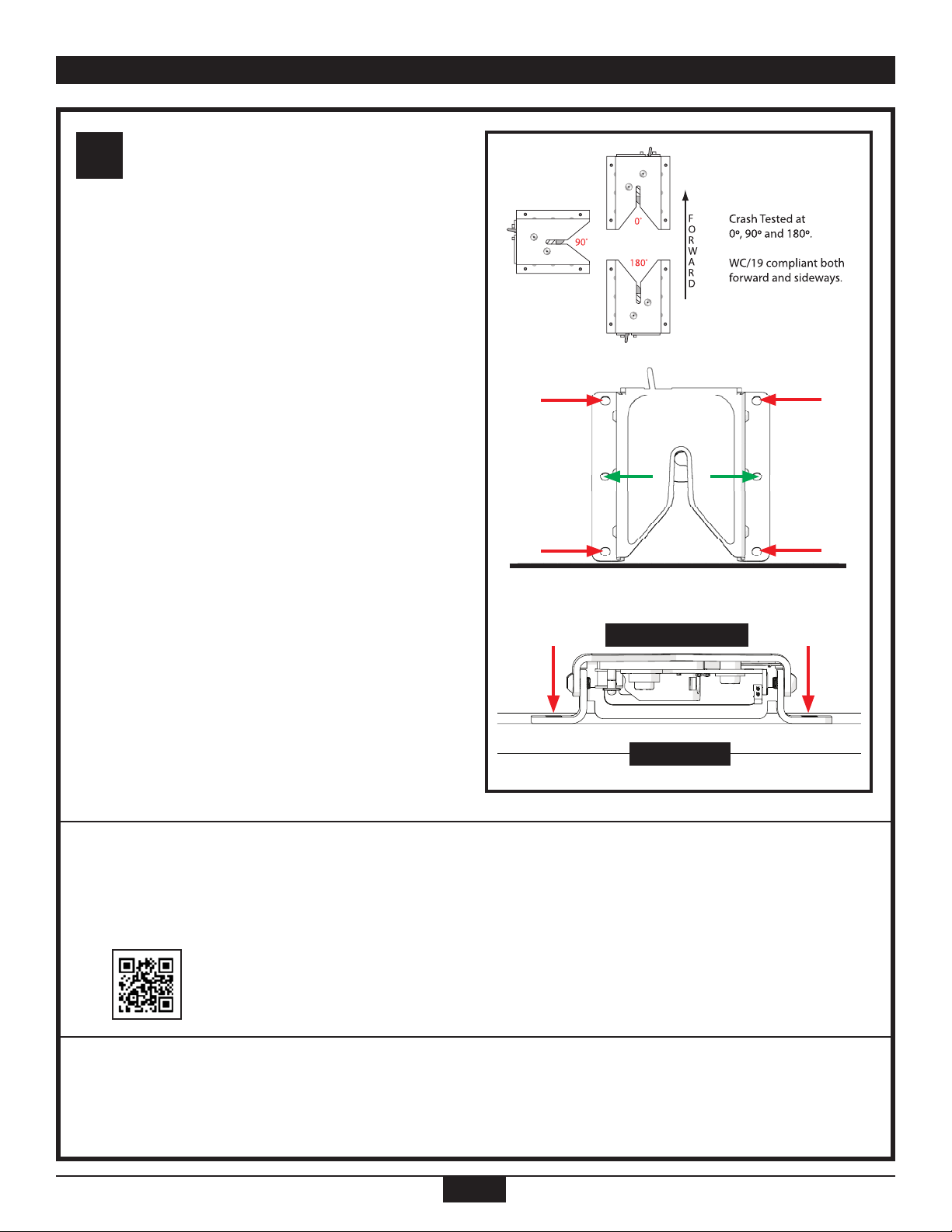
VERIFY WHEELCHAIR ANCHORAGE POINT STRENGTH!
The QLK® Wheelchair Docking System plaorm anchorages and hardware must be installed with a minimum torque requirement of 30 FT-LBS directly
into the vehicle oor structure with reinforcement, as required. The installer must ensure that the wheelchair anchor installaon points do not, as
individual anchors or as a complete system, damage or weaken the vehicle structure.
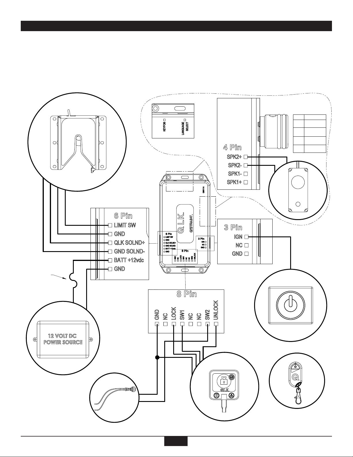
VERIFY ELECTRICAL WIRE ROUTING!
Determine the most eecve and protecve roung methods for the electrical wires so to prevent pinch points, wire chang, sharp edges, or corroded or
exposed metals since any of these condions could damage the wires and cause a malfuncon of the QLK® Wheelchair Docking System.
SUPPORT WHEELCHAIR SPACE!
The QLK® Wheelchair Docking System wheelchair space, dened as the surface where the wheelchair rests, must include ooring frames, or cross-
members, capable of supporng the expected weight of the wheelchair, occupant, and any addional equipment that may be transported. The installer
is responsible for ensuring that the wheelchair space structure, or any cross bracing, complies with applicable regulaons, standards, and performance
requirements for the vehicle.
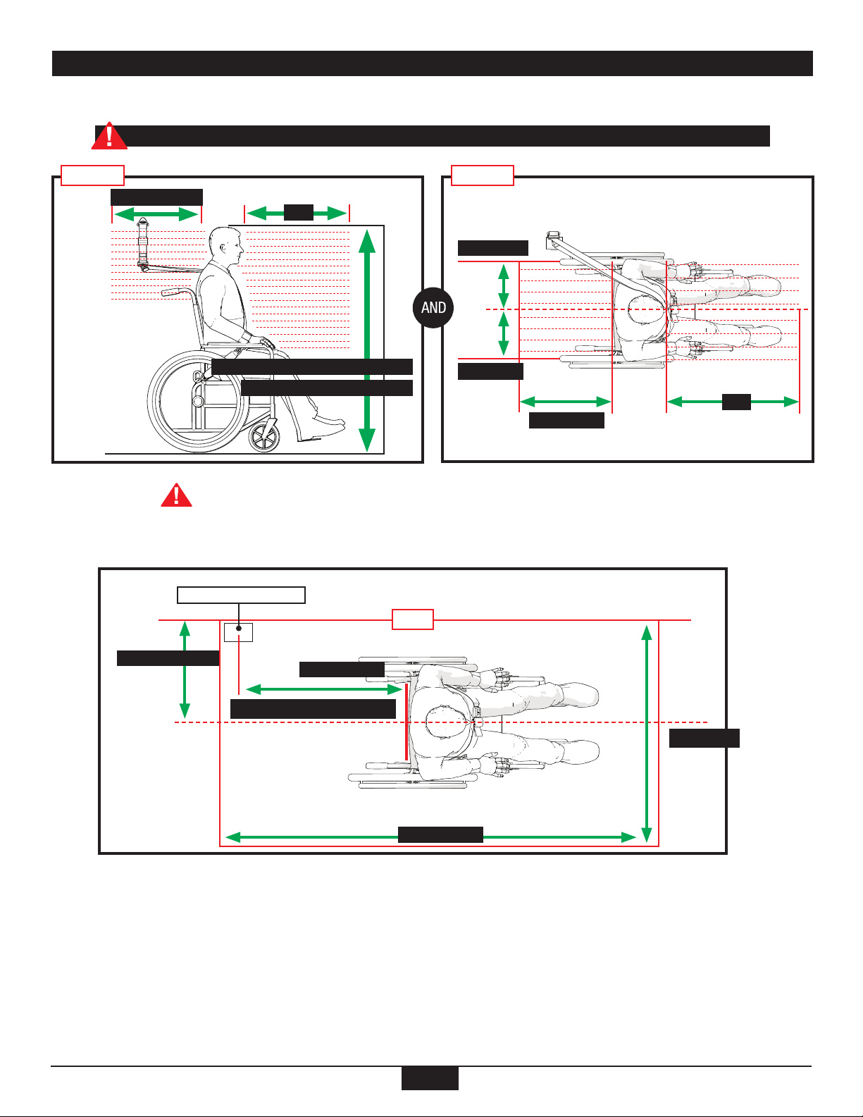
OPTIMIZE WHEELCHAIR LOCATION!
The QLK® Wheelchair Docking System must be posioned to allow for proper wheelchair access and space. Remove any obstrucons from the rear,
front, le and right of the wheelchair area that prevents proper securement of the wheelchair and occupant. Do not allow elevaon or an incline of the
wheelchair as it will interfere with proper securement and may create risk for wheelchair p-over.
FORWARD FACING ONLY!
This QLK® Wheelchair Docking System must only be installed for use with forward-facing wheelchairs and occupants.
VERIFY SAFE AIRBAG LOCATION!
Airbags should only be used as an added safety device in conjuncon with the QLK® Wheelchair Docking System. Airbags can cause serious injury if the
wheelchair occupant sits too close to the airbag module. Do not disable the airbag without rst contacng the vehicle manufacture.
VERIFY OCCUPANT RESTRAINT INTEGRITY!
The occupant restraint (lap and shoulder belt) must be installed into a vehicle frame structure using the provided hardware. The belts must be protected
from contacng any sharp edges of any vehicle components. Improper installaon or posioning of the occupant restraint (lap and shoulder belt) may
place the passenger at a greater risk of serious injury or death during normal vehicle travel, emergency maneuvers, or a crash.
DO NOT MODIFY!
The QLK® Wheelchair Docking System is a completely integrated system. Do NOT alter or modify any poron of the system and do not interchange or
substute any components or subassemblies from dierent manufacturers as they are not compable and such changes may compromise the funconality
of the unit, occupant safety, or load distribuon. Any deviaon from these requirements is the sole responsibility of the installer or user.
USE Q’STRAINT PRODUCTS ONLY!
Only use Q’STRAINT approved replacement components and subassemblies for the QLK® Wheelchair Docking System.

5
CONDUCT PRE-TRIP INSPECTION!
The QLK® Wheelchair Docking System and its components must be inspected for proper operaon prior to each use. Do NOT use this product if it does
not operate, or funcon, as instructed in this manual.
DOCKING STATION SECUREMENT!
Do NOT place the vehicle in moon unless the wheelchair docking bolt is secured inside the QLK docking staon, the GREEN Light is illuminated, and
the occupant restraint system (lap and shoulder belt) is properly posioned on the occupant. Do NOT use the Docking Staon if the warning buzzer is
beeping (Voice states “WARNING - CHAIR NOT SECURED”), or if the dash control is non-operaonal or if the RED light is illuminated.
INSPECT AND MAINTAIN!
The QLK® Wheelchair Docking System and its components must be inspected regularly, cleaned, and maintained. Care must be taken to prevent
contaminaon of the webbing and components from any foreign substance such as polishes, oils, chemicals, abrasive cleaners, or baery acid as such
substances may damage the surface and operaon of the QLK® Wheelchair Docking System. Protect the QLK® Wheelchair Docking System during
vehicle cleaning.
DO NOT USE DAMAGED COMPONENTS!
Replace any damaged, frayed, broken, defecve, worn, or contaminated system components, subassemblies, or webbing.
DISCONTINUE USE AFTER A VEHICLE COLLISION!
The QLK® Wheelchair Docking System and components, including the oor and wall anchorages, must be replaced aer a vehicle collision.
EMERGENCY RELEASE!
ONLY press the RED emergency release lever during an emergency or a vehicle power outage. Do NOT press the manual RED emergency release lever
while the vehicle is in moon as this acon will release the wheelchair.
BUCKLE UP!
The Occupant Restraint (Lap and Shoulder Belt) MUST be properly worn while the vehicle is in moon. Improperly secured passengers are at greater risk
of serious injury or death and may p over or be ejected from the wheelchair during normal vehicle travel, emergency maneuvers, or crashes.
The QLK® Wheelchair Docking System has been successfully dynamically tested with a crash-test dummy restrained by both lap and shoulder belts. The
use of only a lap belt may compromise the performance of the Wheelchair Tiedown and Occupant Restraint (WTORS) system and increase the risk of
serious or fatal injuries to the wheelchair occupant.
The occupant restraint (lap and shoulder belt) must be placed across the occupant’s shoulder and pelvis (lap). The webbing must not be twisted, held away
from the occupant’s body, interfere with any secon of the wheelchair, or exposed to any sharp corners or edges.
MANUFACTURER APPROVED WHEELCHAIRS ONLY!
A wheelchair is not intended to be used as a seat in motor vehicles unless it’s compliant with RESNA WC-4, Secon 19, ISO7176-19, and designed to
allow the transfer of loads through the wheelchair. Refer to the wheelchair manufacturer for further informaon.
REMOVE ADDED EQUIPMENT FROM WHEELCHAIR!
Due to variaons of wheelchair designs, occupant size and weight, and loading ramp angles, any addional equipment or luggage being carried on the
wheelchair or with the occupant may create a hazardous condion for the wheelchair and its occupant to p backwards, or sideways. We therefore
recommend that all addional equipment and luggage are removed from the wheelchair or occupant prior to boarding, maneuvering, or removal from the
vehicle.
PRODUCT COMPLIANCE
The QLK® Wheelchair Docking System complies to the applicable secons of RESNA WC-4 Secon 18, ISO 10542-1, 49 CFR Part 38 ADA, Part 571
FMVSS 209 & 302, 36 CFR Part 1192 ADA
QUESTIONS? CONTACT Q’STRAINT!
For any quesons regarding the installaon, safe operaon, securement procedures, troubleshoong,
maintenance, or general servicing of the QLK® Wheelchair Docking System:
IMPORTANT SAFEGUARDS AND WARNINGS CONT.

6
HARDWARE MANUAL RELEASE (OPTIONAL) DOCUMENTS
SPEAKER (AUDIBLE) IGNITION 12 VDC SYSTEM POWER 12 VDC
DASH CONTROLLER WIRELESS KEY FOB (AUDIBLE) AUXILIARY RELEASE SWITCH
SYSTEM OVERVIEW - QLK
QLK DOCKING STATION CONTROL MODULE CONTROL MODULE (AUDIBLE)
REV
PRN
DESCRIPTION
BY
APV
DATE
1
INITIAL DESIGN

7
Please CONTACT Q'STRAINT in the event that the vehicle’s dimensions are outside the recommended installaon instrucons.
QLK SECUREMENT SYSTEM LAYOUT
Frontal Clear Zones (FCZ) = 26” (660mm) with Shoulder Belt
We recommend using Shoulder and Lap Belts to reduce the possibility of head and chest impacts with vehicle
components. FCZ may not be achievable with wheelchair-seated drivers.
Top View
Layout for All Anchorages
From 40” (1016mm) for 6-Year Old Child)
To 61” (1549.4mm) for a Tall Adult
FCZ
17.72” (450mm)
Side View
8” (200mm)
8” (200mm)
816” (450mm)
FCZ
Wall
19” (483mm) Max 2" (51mm) Min
4” (101mm) - 20” (508mm) Max
48” (1220mm)
30” (762mm)
Shoulder Belt Anchorage

8
ELECTRICAL REQUIREMENTS
1. Power source of 12VDC (11VDC-16VDC) at 12 Amps.
2. Ignion signal of 12 VDC at 12 Amps.
3. Speaker input and language selecon is for QLK AUDIBLE only
4. Follow schemacs shown below for all connecons.
CONTROL MODULE
D
AUXILIARY
RELEASE
M
IGNITION
(12 VDC)
12 AMPS/32 VOLTS
FUSE
N
P
R
KEYFOB
DASH CONTROLLER
AUDIBLE
ENG
FR
SP
BEEP
LANGUAGE
SELECT MODES
1 2 3
SPEAKER
QLK DOCKING STATION

9
QLK INSTALLATION
Install Wheelchair Bracket Interface
Follow the installaon instrucons that come with the
bracket. This will vary depending on the wheelchair
model.
Align height of bolt with height of QLK
Docking Staon
Use a at head screwdriver to ensure the proper gap
between the head of the bolt and the locking pawl.
Opmize Wheelchair Locaon!
The Wheelchair should be located to allow for
proper access to the wheelchair space. Remove any
obstrucons from the rear, front, le and right of the
wheelchair that may prevent the QLK Docking Staon
from properly securing the wheelchair.
Max Distance .125”
Locking Pawl
Head of Bolt
3.
2.
1.

10
QLK INSTALLATION
Posion the Docking Staon
Select the posion of the docking staon 0°, 90°, or
180° to allow for proper wheelchair access. Do not
allow elevaon or any form of incline that exceeds 14°
degrees.
Make sure the docking staon is leveled and parallel with
the vehicle oor.
Mark the locaon of the QLK Docking Staon on the
oor for permanent mounng.
Remove QLK Docking Staon before drilling holes
Verify Vehicle Structure!
Inspect and verify the underside locaon of the vehicle oor, ulies, frames, cross-members, fuel tanks and other
possible obstrucons that may aect the proper installaon of the QLK Docking Staon. Do NOT install anchorages
or any other system components into faulty or non-durable materials such as corroded metal, wood, plasc, or
berglass panels.
For Hybrid models, be sure to disable the high-power wire
to prevent injuries and damage to the product.
(See QR Code instrucons on how to disable)
Verify Vehicle Flooring!
The QLK Docking Staon plaorm must be installed directly into the vehicle ooring structure with addional
reinforcement, if required. The installer is responsible for ensuring that the installaon anchor points are installed
into a structure that conforms to applicable regulaons, standards, and performance requirements for the vehicle.
4.
Vehicle Floor
Leveled and Parallel

11
QLK MOUNTING
Drill 3/8” holes at the marked locaons
a. Drill 6 holes for wheelchairs over 85 Kg (187 lbs)
or WC19 wheelchairs with integrated lap belts
b. Drill 4 holes for Wheelchairs under or equal to 85
Kg (187 lbs).
c. Ensure that the QLK Docking Staon installaon
points do not, as individual anchors or as a
complete system, damage or weaken the vehicle
structure.
Install supplied Hardware
a. Line up the mounng holes and insert the bolts
through the vehicle oor.
b. Place the supplied washers as illustrated and
ghten the nut to minimum torque value of 30
FT-LBS.
Install Control Module
a. Determine the locaon for the Control Module
and most protecve roung methods for the
electrical wires so to prevent pinch points, wire
chang, and sharp edges. The Control Module
must be installed in the interior secon of the
vehicle, preferably under the dashboard.
b. Permanently secure the Control Module at the
selected locaon
7.
6.
5.

12
QLK MOUNTING
Install Dash Controller
a. Determine the locaon for the Dash Controller and
most protecve roung methods for the electrical
wires so to prevent pinch points, wire chang, and
sharp edges.
b. Clean the surface are where the Dash Controlled
will be placed
c. Peel o adhesive lm and rmly install Dash
Controller.
d. Route and connect the Dash Control wires to the
Control Module.
Note: The adhesive lm can take up to 48 hours to
permanently adhere onto the surface area.
Install Auxiliary Release Switch
(Oponal)
a. Determine the locaon for the Auxiliary Switch
and most protecve roung methods for the
electrical wires so to prevent pinch points, wire
chang, and sharp edges.
b. Drill a 9/16” holes at the selected locaon
c. Connect wires to the Auxiliary Switch.
d. Route wires from Auxiliary Switch to the control
Module.
e. Connect wires to the control Module (GND and
SW2).
Connect Docking Staon to Control
Module
a. Route Cable from the QLK Docking Staon to the
Control Module.
b. Plug 6 PIN connector to the Control Module.
10.
9.
8.

13
QLK MOUNTING
Ignion connecon
Connect the white wire to an ignion acvated 12V
source through a 10-amp fuse (or SAE approved
equivalent).
Main power connecon
a. Disconnect the main power source.
b. Determine the locaon for the Main Power Wires
and most protecve roung methods for the
electrical wires so to prevent pinch points, wire
chang, and sharp edges.
c. Connect the red wire from a constant 12V source
( preferably vehicle baery) to PIN 5 (BATT + 12
VDC) of the Control Module.
d. Connect black wire from chassis ground to PIN 6
(GND) of the Control Module.
Key Fob Pairing (Audible Version)
a. Hold “KEY FOB” buon on the Control Module for
5 seconds unl the light on the Control Module
ashes red.
b. Press the buon on the key fob. The light on the
Control Module will now be green for 5 seconds,
showing that the key fob is paired.
13.
12.
11.

14
QLK MOUNTING
Speaker Connecon (Audible)
a. Determine the locaon for the Speaker and most
protecve roung methods for the electrical wires
so to prevent pinch points, wire chang, and sharp
edges. The Speaker must be installed in the interior
secon of the vehicle, preferably next to the
Control Module.
b. Permanently Secure the Speaker at the selected
locaon
c. Route and connect the Speaker cable to the
Control Module.
d. Adjust knob clockwise to increase volume.
14.
Contact the vehicle OEM of the van conversion company if you have diculty locang a proper
power, ignion, or grounding source.

15
QLK SYSTEM OPERATION
MANUAL RELEASE
EMERGENCY Release Lever
DASH CONTROL BUZZER
MODE
Vehicle is OFF
Vehicle is ON
OFF
ON
AUDIBLE (OPTIONAL)
“Warning, Chair is Not Secured”
(connuous beep)
Light OFF
Light ON (RED)
5.
OFF
DOCKING STATION
NOT SECURED (UNLOCKED)
DASH CONTROL BUZZER
MODE
Vehicle is OFF
Vehicle is ON
Unlocked
Unlocked
OFF
ON
AUDIBLE (OPTIONAL)
OFF
Light OFF
Light ON (RED)
1.
“Warning, Chair is Not Secured”
(connuous beep)
DOCKING STATION
RELEASE
DASH CONTROL BUZZER
MODE
Vehicle MUST be
OFF to release.
Note: Wheelchair must
be away from entry
point of the docking
staon to release
locking mechanism.
OFF
AUDIBLE (OPTIONAL)
“Chair is Released”
Press unlock icon
Solid Red light turns on for
10 seconds
4.
Unlocks
DOCKING STATION
SECURED (LOCKED)
DASH CONTROL BUZZER
MODE
Vehicle is OFF
Vehicle is ON
Locked
Locked
OFF
OFF
AUDIBLE (OPTIONAL)
“Chair is Secured”
Light ON (GREEN)
Light ON (GREEN)
2.
“Chair is Secured”
OCCUPANT RESTRAINT (Buckle Up!)
The Occupant Restraint (Lap and Shoulder Belt)
must be worn while the vehicle is in moon.
3.

16
QLK PRODUCT MAINTENANCE
• Inspect and verify the funconality of QLK® Wheelchair Docking System.
• Inspect for damaged subassemblies, wire chang, and components. Replace any damaged, frayed, wires, fuses, broken, defecve,
corroded, worn, or contaminated components, subassemblies, or webbing with Q’Straint approved products only.
• Prevent contaminaon of the any webbing and components from polishes, oils, chemicals, abrasive cleaners, and baery acid
• Clean the QLK® Wheelchair Docking System with a nonabrasive cloth, mild soap, and warm water. Do NOT power wash or use
connuous spray as this will cause internal mechanical or electrical damage.
• Do NOT alter or modify any poron of the system, components, or subassemblies. Do not interchange or substute any
subassemblies from dierent manufacturers.
• The QLK® Wheelchair Docking System does not require any lubricaon.
• Record all performed maintenance below.
PART NUMBER LOT OR SERIAL NUMBER INSTALLATION DATE MAINTENANCE FREQUENCY
MONTHLY
MAINTENANCE LOG
DATE BY COMMENTS DATE BY COMMENTS

17


www.qstraint.com
This manual contains the most current informaon at the me of prinng. Q’STRAINT® reserves the right to modify systems, components and content without noce.
This manual was printed on 30% post-consumer stock using vegetable oil based inks and is 100% recyclable.
© 2023 Q’STRAINT®. All Rights Reserved. QLK® is a registered trademark of Q’STRAINT®, Inc.
FOR TECHNICAL SUPPORT OR TO FIND YOUR NEAREST AUTHORIZED DEALER:
Q’STRAINT Europe
72-76 John Wilson Business Park
Whitstable, Kent, CT5 3QT
United Kingdom
Tel: +44 (0)1227 773035
Fax: +44 (0)1227 770035
Q’STRAINT America
4031 NE 12th Terrace
Oakland Park, FL 33334
Tel: 800-987-9987
Fax: 954-986-0021
Email: [email protected]
Q’STRAINT Australia
Tramanco Pty Ltd.
21 Shoebury Street,
Rocklea, Australia, QLD. 4106
Tel: +61 7 3892 2311
Fax: +61 7 3892 1819
Email: info@tramanco.com.au
QC17479 Rev. C
Table of contents