QRPGuys Pacificon KD1JV User manual

Page 1 of 19 pacificon_assy_041621.pdf
The KD1JV Pacificon
A DSB/CW transceiver for 40 meters.
Featuring: Wide tuning range digital VFO with 5 digit LED readout.
Direct Conversion receiver
~5 watt CW/PEP transmitter
The CalQRP club wanted a simple transceiver with voice capability for a Pacificon build-a-thon. The
goal was to have a QSO party using the project at the end of the build-a-thon.
The other two design goals were low cost, reasonably simple design and hopefully most can build
it in under two hours. DSB was chosen since it's a lot simpler to implement then a SSB transceiver
and is somewhat more effective than AM.
Conventional wisdom says two DSB stations can't talk to each other if both use a Direct
Conversion receiver. This is not true.
What is true is that the two stations need to match each other's frequency exactly. Or at least
really close. As the center frequency of one or the other (or both) stations start to drift apart, the
beat note of each side band starts to separate, with annoying results.
The problem with minimalist DSB designs is that they often used an Analog VFO of questionable
stability. So, keeping two home brew DSB stations on the same frequency was frustrating, hence
the bad rap.
By using the inexpensive Si5351 clock chip for the VFO and the various additional functions a
microprocessor adds, The Pacificon becomes a practical DSB rig.
The firmware is written with the Arduino IDE. The MEGA328P processor comes with the bootloader
installed, making it compatible with the UNO board for reprogramming. The Arduino sketch is
available to tinker with.
A Baofeng UV3R, (not UV3R+), single plug microphone is required for voice operation. These are
available on ebay for $5 to $10 depending on who you buy from and how long you want to wait
for it.

Page 2 of 19 pacificon_assy_041621.pdf
Specifications:
DSB/CW Transceiver for 40 meters.
Tuning range 500 kHz to 30 MHz (actual range limited by band filter
characteristics)
Direct Conversion (DC) receiver.
Receiver MDS: ~0.5 uV
Audio Bandwidth: Wide: 4,000 Hz Narrow : 1,000 Hz
Double Side Band (DSB) transmitter. Up to 5 watts PEP, ~5 W typical. (power is
split between two side bands, so effective PEP is 2.5 watts)
CW Transmit Mode. Up to 5 watts.
Rx current : ~40 ma
Tx Current : (CW) ~650 ma @ 13.8 V, 4.5 watts out.
TX spurs, well below -50 dBc.
12 to 14V supply
Assembly:
The first step is to sort the parts into groups of similar types. Doing this now will save
time later.
Print the placement diagram below for easy reference. Experienced builders will need
little more than this diagram.
Part locations are color coded using the resistor color code to indicate the zero multiplier
of the part value to be placed there. Since several values use the same zero multiplier,
pay attention to the most significant digits.

Page 3 of 19 pacificon_assy_041621.pdf
Parts list:
QTY
Value Code
QTY
Value Code
2 5.6 ohms Grn/Blu/Gld/Gld
16 100 nF (.1uF) 104
1 10 ohms Brn/Blk/Blk/Gld
5 10 nF (.01 uF) 103
1 51 ohms Grn/Brn/Blk/Gld
3 1 nF (.001uF) 102
1 150 ohms Brn/GRN/BRN/Gld
2 680 pF 681
13 2.2K Red/Red/Red/Gld
3 330 pF 331
2 4.7K Yel/Vio/Red/Gld
1 68 pF 68
8 10K Brn/Blk/Org/Gld
2 47 pF 47
1 22K Red/Red/Org/Gld
2 47K Yel/Vio/Org/Gld
3 1 uF/25V electrolytic
3 100K Brn/Blk/Yel/Gld
5 100 uF/16V electrolytic
1 470K Yel/Vio/Yel/Gld
2 1M Brn/Blk/Grn/Gld
1 25K 9mm pot
1 Si5351A
1 2K 6mm trimmer
1 1N5817
5 1N4148
3 10 uH molded inductor
1 2N3906 PNP TO-92
2 2N3904 NPN TO-92
1 16.000 MHz HC-49S
8 BS170 MOSFET TO-92
1 25.000 MHz HC-49S
1 LM78L05 5V reg TO-92
1 LM78L09 9V reg TO-92
1 5 digit 7 seg LED display 0.38”
1 ATMEGA328P AVR processor
1 SA602 or 612A Mixer DIP
2 T37-2 Red Toroid
1 LM356 Dual opamp DIP
2 FT37-43 Black Toroid
1 LM386 Audio amp DIP
3 8 pin DIP socket
1 6 feet #26 red magnet
1 28 pin DIP sokt
1 1 foot #26 grn magnet
1 12mm encoder
1 PCB BNC jack
1 pcb Pacificon pcb
1 3 ring 3.5mm
jack
Mic/spkr jack
1 5.5-2.1 mm DC power jack
2 SPDT slide
switch
2 3 wire plug &
socket pigtail
External spkr &
keyer connections

Page 4 of 19 pacificon_assy_041621.pdf
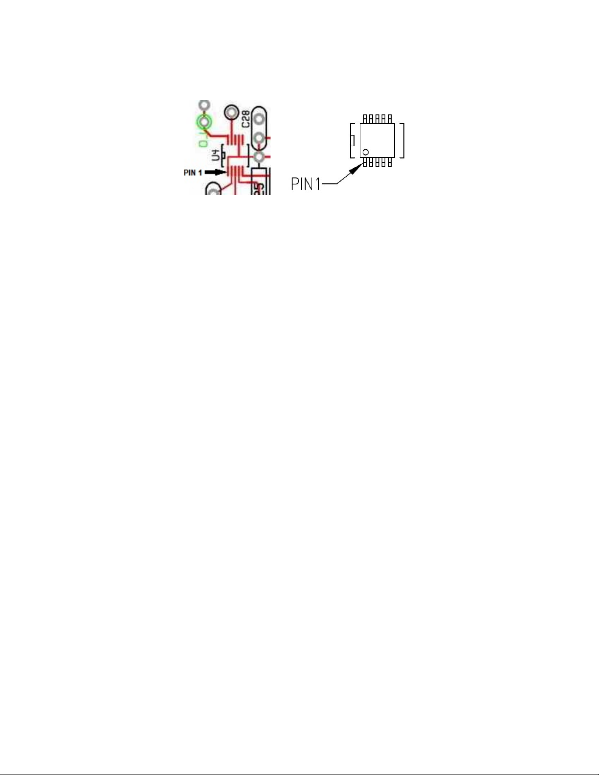
[] Solder U4, the Si5351A smd component first. Position as shown below. Note
orientation of Pin1. Be sure there are no solder bridges between pins. Use Solder Wick® if
necessary to remove any excess.
Resistors:
Some values who's color codes are very similar are easy to mix up. It's important to
pay attention to the multiplier band to make sure you have the correct decade. Pay
attention to the 2.2K and 22K, 4.7K, 47K and 470K values, along with 51 ohms and
1M. These are easy to mix up. When in doubt, use a ohmmeter to measure.
Locations are numbered on the board left to right, starting at the upper left corner
and then zigzag down the board.
[] 5.6 ohms - R1, R5 (Green-Blue-Gold-Gold)
[] 10 ohms - R35 (Brown-Black-Black-Gold)
[] 51 ohms – R12 (Green-Brown-Black-Gold)
[] 150 ohms - R13 (Brown-Green-Brown-Gold)
[] 2.2K – R4, R6, R9, R10, R23, R27, R28, R29, R30, R31, R32, R33, R34, (Red-Red-
Red-Gold)
[] 4.7K – R7, R15 (Yellow-Violet-Red-Gold)
[] 10K – R2, R14, R17, R19, R20, R24, R25, R26 (Brown-Black-Orange-Gold)
[] 22K – R21 (Red-Red-Orange-Gold)
[] 47K – R3, R11 (Yellow-Violet-Orange-Gold)
[] 100K – R8, R16, R18 (Brown-Black-Yellow-Gold)
[] 470K – R22 (Yellow-Violet-Yellow-Gold)
[] 1M – R36, R37 (Brown-Black-Green-Gold)
Inductors (RFC):
[] 10 uH – L1, L2, L3 (Brown-Black-Black-Gold or Silver)
Diodes:
[] 1N5817 – D1 – Black plastic body, silver stripe on one end, match silkscreen
[] 1N4148 – D2, D3, D4, D5, D6 – Glass body, black stripe on one end, match
silkscreen
Capacitors:
Since most of the caps are 100 nF (104), we'll put all of those in first. Look at both
sides of the capacitors carefully, as most have a confusing date code on the reverse.
[] 104 – C1, C5, C8, C9, C10, C11, C14, C19, C21, C23, C28, C31, C35, C36, C39,
C40

Page 5 of 19 pacificon_assy_041621.pdf
[] 331 - C2, C3, C37
[] 681 - C4, C27
[] 68 - C6
[] 103 – C13, C22, C26, C30, C32
[] 102 – C7, C12, C15
[] 47 – C18, C20
Crystals:
[] 25.000 - X1
[] 16.000 - X2
Sockets:
[] 8 pin DIP – U1, U2, U5
[] 28 pin DIP - U4
Make sure to line up the notch on the socket with the one on the board
outline.
Check to make sure all the pins are sticking out of the holes before you
solder more than one pin. Finding a pin rolled under the socket after all the
other pins have been soldered is not an easy fix.
LED Display:
Now is a good time to install the display, before the higher profile parts start to
get in the way of the soldering iron.
[] LED Display – flip the board over and install the display flush with the surface.
It will go in only one way due to a missing pin and corresponding pad on
the board.
Clip the leads while you can still get the cutters in there.
Transistors:
[] BS170 - Q2, Q3, Q4
These are mounted with the flat side of the package flat to the circuit board
for heat sinking.
Bend the leads towards the flat side at a 90 degree angle, about 1/8” from
the body.
Make “U” shaped wires from resistor lead clippings to hold the package
down onto the board, using the solder pads on either side of the package.
Solder the BS170 leads.

Page 6 of 19 pacificon_assy_041621.pdf
[] BS170 – Q7, Q8, Q9, Q10, Q11
[] 2N3904 – Q1, Q6
[] 2N3906 – Q5
[] 78L05 - U7
[] 78L09 – U2
[] V1 2K trimmer
Electrolytic caps:
[] 1 uF/25V – C24, C29, C33 – long lead is plus
[] 100 uF/16V – C16, C17, C25, C34, C38 – long lead is plus
Jacks:
[] 3.5 mm Jack – J3
[] Power jack – J2 -needs a lot of heat.
[] BNC jack – J1
Toroids:
Trim all the toroid leads to 3/8” and tin with solder before installing.
[] T1 – FT37-43 BLACK core – 5 turns wire pair.
Use 6” of both #26awg red and green magnet wire.
Use an ohmmeter to identify the common ends of the wires
and arrange them so that they are opposite each other as
shown.
The wires will now be in the proper positions for inserting into
the board.
[] L4 – T37-2 RED core – 18 turns of #26awg magnet wire
[] L5 – T37-2 RED core – 20 turns of #26awg magnet wire
[] L6 – FT37-43 BLACK core – 5 turns of #26awg magnet wire
[] J4,5 - sockets for the 1x3 pigtailed connectors.
Both J4-speaker and J5-keyer are keyed connectors. Be sure to match the
keying slots for the plugs facing the right side of the board. This is
necessary for the correct color coding of the leads in the further
connections of the J4-external speaker and or J5-SKC Keyer.
This completes the bottom side assembly.

Page 7 of 19 pacificon_assy_041621.pdf
Top side:
Only three parts to install now.
[] EC1 – encoder
[] V2 – volume pot
[] S1, S2 – SPDT slide switch.
Add a couple of temporary jumpers:
There are provisions for adding an optional ON/OFF switch and external
speaker/headphone jack. Until these options are installed, jumpers must be
installed so the board gets power and the speaker/mic speaker is connected.
Use a piece of resistor lead clipping to make the jumpers. These can be installed
on the display side of the board for easier access and future removal.
Speaker
Jumper
ON-O FF
Jumper

Page 8 of 19 pacificon_assy_041621.pdf
Initial Power up:
Before you apply power to the circuits, spend a few moments to inspect your
work. Soldering issues are the most common cause of a kit not working first and
every time.
Grounds take a little more heat than connections to tracks, so look at these
carefully to make sure the solder didn't just stick to the lead.
Use an ohmmeter to check for continuity through the toroids. Not fully
stripping the magnet wire and making a good connection is a common
problem.
If T1 is installed correctly there will be continuity between all four pads.
Before any of the IC's are installed into their sockets, it's a good idea to
check to see if the voltage regulators are working correctly.
Apply power to the board.
Check for 9V – Pins 8 (+) and 4 (-) of the U3 socket is a good place to
check.
Check for 5V – Pins 7 (+) and 8 (-) of U5 is a good place to check.
Good to Go?
Insert the MEGA328P processor into the 28 pin socket. Make sure it goes in the
correct way, although it will not be damaged if powered up in wrong way. (this is
not true of the other ICs)
Plug in your supply (12 to 14V) and turn it on.
If all is well, The display will read [ bn40P].
If it didn’t, did you jumper the “On-Off” pads?
The data for the selected band is now loaded, the default operating
frequency displayed and the board is now ready for additional testing.
Remove power.
You can now install the rest of the ICs.
▪ [] U1 – SA602
▪ [] U3 – LM358
▪ [] U6 - LM386
Connect up your antenna
Plug in the speaker/mic
Turn power back on
Turn the volume up and you should hear band noise. Tune around and find
some stations.
So far so good? If not jump to the trouble shooting guide, p16.

Page 9 of 19 pacificon_assy_041621.pdf
Transmitter testing:
The bias current for the linear PA needs to be set.
You might as well connect up a power meter and dummy load now.
Connect an ampmeter in series with your power supply. The 200 ma.
setting should be fine.
Turn V1 fully counter clockwise.
In DSB mode, key the transmitter and note the current.
Adjust V1 until the current increases by 40-50 ma.
If you don't have an ampmeter, set V1 to about the 2 O'clock position.
If the current does not increase, you have a problem with the solder
connections on T2.
Set the mode switch to the CW position.
Key the transmitter and note the power output.
▪ 40M – ~5 watts.
Switch back to DSB mode and check to see that you modulate when
speaking into the microphone by seeing power output on your meter.
Your DSB PEP power will be about ½ the CW power due to the power being
split between the two side bands. Average power will be much less.
Calibration:
Now that everything is working, do the frequency calibration. Until this is done,
the actual frequency maybe (and most likely) off from the dial by up to 500 Hz.
There are two ways the LO can be calibrated.
1. Use a frequency counter. The LO signal is available at the test point labeled
“LO” on the top side of the board.
2. Zero beat a SWBC station. These are easy enough to find in the evening
and are on exact 5 kHz clicks.
Entering Calibration Mode:
A 5 second push of the Encoder actives Calibration mode
Release the Encoder when [CAL ] is displayed.
The VFO reference oscillator can now be tuned with the encoder to calibrate
the frequency.
This can be done in one of two ways.
1. Use a frequency counter at the LO test point.
◦ Tune to match the frequency which was on the display when CAL was
entered. To help you remember what frequency that is, the frequency
◦ will re-appear on the display, but leading with “C” to indicate you are
in CAL mode.

Page 10 of 19 pacificon_assy_041621.pdf
2. Zero beat an AM SWBC station. To use a broadcast station, you need to first
tune it in, knowing they are on exact 5 kHz frequencies. Since you are
slightly off frequency, the audio will be wobbly. Active the Calibration mode
and tune the VFO until the wobble in the audio goes away. A scope will help
with this and get you closer then you can just by ear. You may not get the
frequencies to exactly match, but you can get pretty close.
Packaging the board:
A custom PCB enclosure is available from QRPGuys. Simple, light and with labeled
controls, it is a good option. If you don't mind doing some metal work, the board
will fit into a 110mm X 88 mm X 38 mm extruded aluminum box, which is
commonly available on ebay. A drill template is located at the end of the manual.
Operation:
The power up sequence is:
The display will do a segment test by lighting all segments. [8.8.8.8.8.]
The band for which the board operates on is displayed [ bnXX]
The default operating frequency is displayed and the rig is ready to operate.
The default tuning rate is 1 kHz.
Display:
The display reads out the operating frequency to 10 Hz. The MHz digits are not
shown and are implied by the band. Below 01.000.00, the leading zero is
suppressed.
When tuned outside the Ham Band, the display will automatically shift to
indicate the MHz digits and the transmitter disabled.
◦ This reduces the display resolution to 1 kHz.
◦ The current tuning rate does not change.
◦ 10 and 100 Hz tuning rates are available, but the display will not
increment until the 1 kHz digit rolls over.
◦ The transmitter is disabled when tuned outside the Ham band. The side
tone will beep if you try to transmit.
◦ General coverage tuning is from 500 kHz to 30 MHz. Tuning outside the
Ham band will reduce sensitivity. Sensitivity will decrease the most when
tuning above the band due to the transmitter's Low Pass Filter. The
Receiver front end is only loosely tuned to the band so shows greater
sensitivity when tuned below the band.

Page 11 of 19 pacificon_assy_041621.pdf
Tuning Encoder Push Button:
The tuning encoder has a built in push button which is used to select several
options.
1 – Change tuning rate.
2 – Enable/disable RIT.
3 – Enable CW mode.
4 – Store a custom default power on frequency.
5 – Calibrate the VFO.
6 – EEPROM erase
1 – TUNING RATE:
A short push and release advances the tuning rate.
A beep will sound.
The selected decade digit will blink off for a 100 ms.
Tuning rates of 10 HZ, 100 Hz, 1000 Hz and 5000 Hz are available.
Since 1K and 5K rates share the same decade digit, the 10 kHz decade
blinks when 5K is selected.
2 – RIT:
A 500 millisecond push of the Encoder activates RIT. Release the switch
when the display reads [rit ]
When RIT activates, the display changes to show the delta frequency from
the transmit frequency. [ r-0.00 ]
RIT tuning rate is changed to 10 Hz. The original tuning rate which was
selected before RIT was enabled will be restored on exiting RIT.
Range is +/- 9.990 kHz.
To exit, push the Encoder again for 500 milliseconds. A beep will sound
when RIT is exited. Release the switch at the beep to restore the main
display.
3 – CW mode: DSB mode is default. CW mode must be set at every start-up
A 1 second push of the Encoder will toggle the CW mode on and off.
Release the Encoder button when the display reads [CodE]
Display for 1 second will read:
◦ [Cd-on] (side tone now on)
◦ or [Cd-oF] (side tone now off)
When CW mode is active, RIT acts differently than normal. See “CW
operation” for details.
4 – Storing a custom default power on frequency:
A 3 second push of the Encoder will store the currently displayed frequency
and will become the frequency at which the rig powers up on.
When the display reads [Str-F], release the Encoder.
The display will flash [Stord] for a second and a beep will sound to indicate
the function occurred.

Page 12 of 19 pacificon_assy_041621.pdf
5 – Calibration:
A 5 second push of the Encoder actives Calibration mode
Release the Encoder when [CAL ] is displayed.
The VFO reference oscillator can now be tuned with the encoder to calibrate
the frequency.
This can be done in one of two ways.
1. Use a frequency counter at the LO test point.
1. Tune to match the frequency which was on the display when CAL was
entered. A frequency ending in 100.00 is a good one to choose.
2. Zero beat an AM SWBC station. To use a broadcast station, you need to first
tune it in, knowing they are on exact 5 kHz frequencies. Since you are
slightly off frequency, the audio will be wobbly. Active the Calibration mode
and tune the VFO until the wobble in the audio goes away. A scope will help
with this and get you closer then you can just by ear. You may not get the
frequencies to exactly match, but you can get pretty close.
6 – EEPROM erase:
A 8 second push of the Encoder will erase the data in the EEPROM which
clears VFO calibration. This is included in case the EEPROM data gets
corrupted or you wish to change filters to a different band.
Unless you really want to do this, best not to push the Encoder too long!
Release the Encoder when the display reads [e-rAS]
Once the Encoder is release the display will read [donE] and a beep will
sound.
Power needs to be cycled to restart with factory values.
Low – Wide switch:
In the [Low] position an audio low pass filter with a roll off starting at 1 kHz is
switched in. This will reduce the high frequency background noise and is primarily
used in CW, but can be helpful in voice reception despite the reduction in fidelity.
When the LPF is enabled, very strong signals will cause motor-boating type
oscillations if the volume is turned up high. Simply turn down the volume to fix
this. This does not seem to be a problem in wide band mode.
It's good practice to leave the volume control set about midway when tuning
around and only turn it up to full when needed. Since there is no AGC, keeping
the volume low when using headphones will save your hearing.
CW – DSB mode switch:
This switch sets the transmit mode to either CW or DSB.
The switch must be in the DSB position for voice operation. When in the CW
position, a carrier (CW) signal will be transmitted. However, there will be no side
tone. Use this as a Tune mode if you need to adjust an antenna tuner.

Page 13 of 19 pacificon_assy_041621.pdf
Voice DSB operation:
Plug in the speaker/mic.
Make sure the mode switch is in the DSB position.
Push the button on the mic and talk.
There is no modulation control, it is based on how loud you talk. Speak in a
normal conversational level. No need to shout or talk loud, you will just
over modulate.
CW operation:
Enabling CW mode:
1. The default mode for the transceiver is the DSB voice mode, therefore as
noted earlier, push the Encoder for 1 second to enable CW mode. Cd-n will
appear, and upon release will display Cd-on. It is a toggle to return to DSB
voice mode. This enables the side tone and affects how RIT works. Tuning
rate is fixed at 100 Hz.
2. Slide the DSB-CW switch to the CW position.
The PTT keys the transmitter.
Unfortunately, the PTT on the Baofeng mic is wired to the 2nd ring on the
speaker/mic and is therefore grounded if a common Stereo or mono plug is
inserted, keying the transmitter on all the time. Not good.
Therefore, a separate 3.5mm 3 ring (4 pole) key jack should be added for CW.
You might also want to add a jack for a speaker or headphones. There are
provisions (J4,J5) on the board for plugging in an optional keyer board and
headphone/speaker jack. Both these options are built into the available Pacificon
chassis kit.
Making CW contacts:
Isn't the easiest thing to do with any Direct Conversion receiver due to hearing
both side bands and having to initially zero beat the desired station to match their
frequency and then using RIT to re-tuning the receiver frequency to hear a beat
note.
The thing to remember is when the audio beat note is decreasing in frequency,
you are headed towards zero beat. If the beat note frequency is increasing, you
are moving away from it. This is true whether your tuning up or down the band.
To make things a little easier, RIT works a bit differently in CW mode. Activating
RIT will automatically offset the receive frequency by 600 Hz. Pushing the
Encoder switch will toggle between + 600 Hz and – 600 Hz so you can select the
side band with the least QRM. You can fine tune from there, the tuning rate is
fixed to 10 Hz.

Page 14 of 19 pacificon_assy_041621.pdf
Calling CQ is the easier option, as all you need to do is find a clear frequency and
activate RIT.
If there's a contest going on, and the band is crowded, I'd find another rig to use!
Adding a linear:
Let’s face it, 2.5 watts PEP isn't a whole lot of power for voice. Although not really
recommended, no doubt there will be those who want to add a linear. In which
case it will need to be switched in and out.
If you wish to directly control the linear (like if you build it into the same box) you
can use the MUTE output from the processor for this. The MUTE output becomes
active high before the transmitter is keyed and releases 100 ms after it is
unkeyed. Buffer this signal with a MOSFET like the BS170 or 2N7000 to activate
a relay for switching in the amp and turning its power on.
Adding a BCI filter:
If you happen to live in an AM broadcast band rich environment, a high pass filter
can be easily built. Construct it in an Altoids box with a couple of BNC’s and place
it between your antenna input to the Pacificon and your antenna. It uses fixed
molded inductors and has a very low insertion loss and sharp cutoff just above
the broadcast band. Thanks to VK3YE from the uBitX group for this idea. His full
description and evolution can be found at:
https://www.youtube.com/watch?v=fgQenFJOjr4
General Coverage Reception:
The receiver front end is only loosely tuned to the selected Ham band the board is
built for. Using an antenna tuner with High Pass characteristics (like a “T”
configuration) will help reduce interference from strong near-by (or not so near-
by) SWBC stations.
When tuning outside the ham band, an antenna tuner can also help enhance
reception or attenuate strong station which are overloading the front end
depending on how you peak it.
Stations in the 49 meter band can be very strong and when the antenna is
peaked for that frequency, the strongest station splatter for many kHz.

Page 15 of 19 pacificon_assy_041621.pdf
With my ladder line feed “88” and MFJ balance line tuner, I can get reception of
stations all the way down into the AM broadcast band. One does have to strain a
bit to hear the AMBC stations.
One characteristic of a Direct Conversion receiver is it will also detect stations at
harmonics of the LO frequency. This will become apparent if a SWBC station
happens to be at the 3nd harmonic of the LO.
Front panel drill drawings:
These will print to actual scale (but make sure your print options are set for
100%, not fit to page.)
The bottom view template is for use when drilling from the back side of the panel,
which is the best way to do it if using the extruded aluminum case. The template
will fit between the rails along the top, inner edge of the shell.
The dimensional drawing is for if you have a CNC machine.
Top view with dimensions.

Page 16 of 19 pacificon_assy_041621.pdf
Side panel drilling dimensions:
Below the dimensions shown in the Y axis are referenced to the bottom of the
board. To this one would have to add the thickness of the board (0.061”) plus the
board mounting spacers and the thickness of the front panel to get the proper Y
distance.
Not knowing the size of the chassis you might use, the dimensions below are
shown from the edge of the board in one axis, and the surface of the board in the
other.
Additional construction note:
There are provisions, as mentioned earlier, concerning J4,5. These are provided
for adding an external speaker, and or, SKC keyer. The mounting holes are
provided for these options in the optional Pacificon Chassis. Mounting instructions
for these additions can be found in the chassis assembly manual. If you exercise
this option, remember to remove the speaker jumper installed earlier. Shown
below are the details for J4,J5 and the optional SKC keyer.
If you are adding the KD1JV SKC Keyer and associated pcb chassis, assemble the
keyer to Option2 in the keyer instructions. Trim the header plug and wire
assemblies to 5” from the far end of the connector to the ends of the three wires
on each of the two assemblies supplied. Strip and tin about 1/8” of each wire.
Wire the interconnecting pigtails as shown below, and use a piece of the trimmed
pigtail wire to connect the “Function Tone” pad to the speaker jack as shown in
“green”. Mount the main SKC board to the bottom of the chassis where indicated
by the outline, with a piece of two sided foam tape. Secure the speaker jack with
the pins down. Secure the speaker jack and keyer jack to the side pcb using the
threaded rings. Plug the pigtails into the correct header.

Page 17 of 19 pacificon_assy_041621.pdf
Wiring note: The speaker jack is shown facing up for connection clarity. Install
the jack with the pins down.
Use the two 4” cable ties to bundle the wires close to the pcb. This reduces the
strain on any individual wire.
[ ] Plug J4 and J5 pigtails into the correct board receptacles, and slide the top
Pcb assembly into the chassis, securing it with the four 3mm x 10mm long
bottom screws.
This completes the assembly
Trouble shooting:
The #1 reason a kit does not work, is soldering issues.

Page 18 of 19 pacificon_assy_041621.pdf
Sometime it will look like you made a good connection, but the solder really only
stuck to the component lead and didn't flow into the pad on the board. These can
be a little tough to spot.
Another common area for a problem is not properly tinning the magnet
wire on the toroid windings. Or, pulling the wire through the pad past the
area which was tinned.
If a visual inspection doesn't spot the problem, the problem area needs to be
identified. The first step is to eliminate the parts which are working.
It helps to have a 'Scope to track signals, but lacking one of those you'll have to
settle for your DMM.
X-Ray view of the board. Use this to see how the parts are connected together.

Page 19 of 19 pacificon_assy_041621.pdf
Other QRPGuys Transceiver manuals
Popular Transceiver manuals by other brands

Alinco
Alinco DR-510T Service manual

Yaesu
Yaesu FT-75B instruction manual

Technisonic Industries Limited
Technisonic Industries Limited TSC-4400 Installation and operating instructions

Kenwood
Kenwood TS-430S instruction manual

Vertex Standard
Vertex Standard VX-5500V Service manual

Bellman & Symfon
Bellman & Symfon BE1433 Medical device information