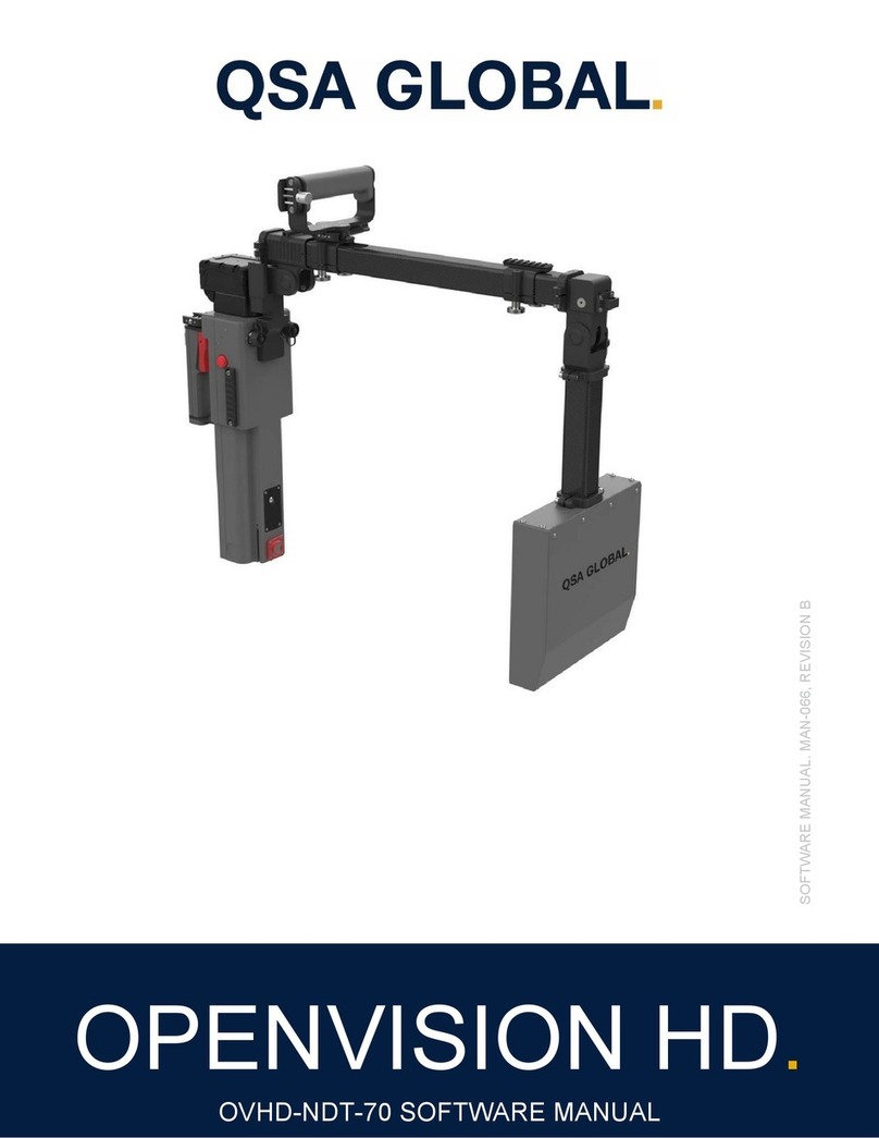
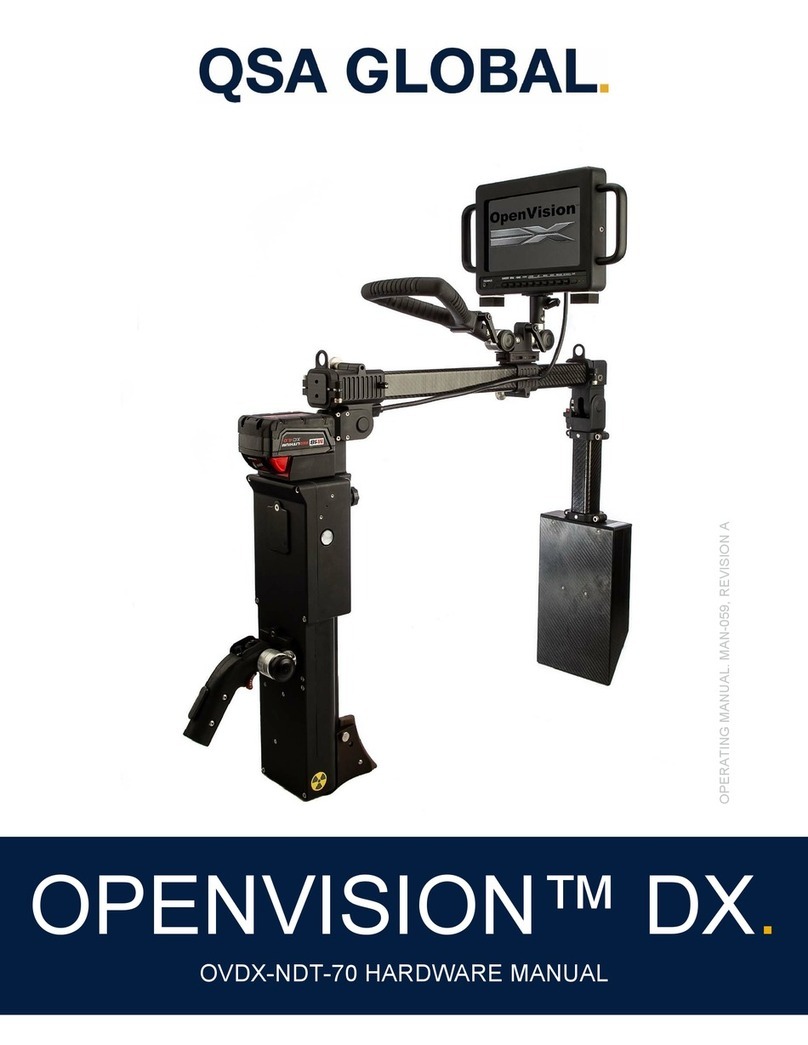
QSA Global OPENVISION DX OVDX-NDT-70 Mounting instructions

SOFTWARE MANUAL. MAN-063, REVISION A
OPENVISION DX.
OVDX-70 SOFTWARE MANUAL

Page 2 of 25
QSA Global, Inc. 40 North Avenue Burlington, MA 01803 888.272.2242 781.272.2000 F: 781.359.9179 qsa-global.com
TABLE OF CONTENTS.
Table of Contents. ................................................................................................................................................................... 2
Introduction. ............................................................................................................................................................................. 3
Equipment Specifications. ....................................................................................................................................................... 3
Safety Precautions .................................................................................................................................................................. 5
Operating Conditions ........................................................................................................................................................... 6
X-Ray Training ..................................................................................................................................................................... 6
Precautions .......................................................................................................................................................................... 6
OpenVision™ Digital X-Ray System (OVDX) Software. ......................................................................................................... 7
Power Cycling ...................................................................................................................................................................... 7
Startup .............................................................................................................................................................................. 7
Shutdown ......................................................................................................................................................................... 7
Home Screen ....................................................................................................................................................................... 8
Settings Menu ...................................................................................................................................................................... 8
Firing X-Rays ..................................................................................................................................................................... 10
X-Ray Live Image Screen .................................................................................................................................................. 11
Image Capture ................................................................................................................................................................... 12
Video Capture .................................................................................................................................................................... 13
System Information ............................................................................................................................................................ 13
Image Playback ................................................................................................................................................................. 14
USB Drive Configuration for Media Transfer ..................................................................................................................... 15
Image Transfer .................................................................................................................................................................. 16
Software Update ................................................................................................................................................................ 19
Admin Password Screen ................................................................................................................................................... 20
System Administration ....................................................................................................................................................... 21
Super Mode ................................................................................................................................................................... 21
Maintenance. ......................................................................................................................................................................... 22
Troubleshooting. ................................................................................................................................................................... 23
QSA Global, Inc. Contact Information ............................................................................................................................... 25
Page 3 of 25
QSA Global, Inc. 40 North Avenue Burlington, MA 01803 888.272.2242 781.272.2000 F: 781.359.9179 qsa-global.com
INTRODUCTION.
The OVDX-NDT-70 and OVDX-SEC-70 are the world’s only hand-held live video X-ray systems designed for corrosion
under insulation and security-related inspections, respectively. With patent pending ergonomic features and improved
weight distribution, operators can quickly set up and begin scanning. Transfer files simply from OVDX via USB drive for
review and inclusion in inspection reports.
EQUIPMENT SPECIFICATIONS.
Table 1 OVDX Specifications
Imaging Area (Field of View) 4 in. x 6 in. (10 cm x 15 cm)
Dimensions
X-ray Tube to Imager
Throat depth
Imager Thickness
X-Ra
y
Tube Thickness
9.5 in. (24 cm) to 20.9 in. (53 cm)
21 in. (58 cm)
2.5 in. (6.4 cm)
3.4 in.
(
8.7 cm
)
Startup Time (est.) 30 seconds
Shutdown Time (est.) 5 seconds
X-Ray Energies
Low
Medium
High
Voltage (kV)
40
55
70
Current (mA)
0.300
0.218
0.171
Dose @ 12 in (30.5 cm) from beam port
50 R/hr (0.5 Sv/hr)
80 R/hr (0.8 Sv/hr)
95 R/hr (0.95 Sv/hr)
Beam Collimation (Approximate) 25° Horizontal
17° Vertical
Image Resolution 0.004 in. (0.1 mm)
Battery Life
Continuous duty with 5 AH battery
Standb
y
3 hours
8 hours
System Weight
C-arm
Monitor w/ handle (optional)
Packa
g
ed s
y
stem
(
shippin
g
wei
g
ht
)
11 lbs. (5 kg)
6.4 lbs. (2.9 kg)
53 lbs.
(
24 k
g)
Operating Temperature -20° F to 120° F
(
-29° C to 49° C
)
Storage Temperature -30° F to 140° F
(
-34.5° C to 60° C
)
Display Options
10 in. LED Monitor: 1024 x 600 pixels
PirateEye: 854 x 480 pixels
Most devices that accept HDMI signals
Recording
Internal storage
Resolution
Ima
g
e / video transfer
128 GB
1280 X 720
USB
Shipping Dimensions 32 in. x 20.5 in. x 12.5 in
(
82 cm x 52 cm x 32 cm
)
FDA Accession # 1680071-000

Page 4 of 25
QSA Global, Inc. 40 North Avenue Burlington, MA 01803 888.272.2242 781.272.2000 F: 781.359.9179 qsa-global.com
The OVDX-NDT-70 and OVDX-SEC-70 are built in compliance with ISO 9001:2015 and meets the following
standards when used as directed:
ANSI/HPS N43.5 (2005)
Ionizing Radiation Regulations (2017)
ISTA 3A Over the Road vibration standard
MIL-STD-810, Method 514, Annex C, Cat 4
REACH/ROHS
HMD
ANSI Z87.1+, US Federal OSHA
US Mil Spec MIL-PRF-31013
CE END 166 FTKN
Battery/Charger
California Energy Commission
Underwriters Laboratory for Canada and U.S.
Revision Record
Revision Date Description
A 06/2019 Production Release

Page 5 of 25
QSA Global, Inc. 40 North Avenue Burlington, MA 01803 888.272.2242 781.272.2000 F: 781.359.9179 qsa-global.com
SAFETY PRECAUTIONS.
WARNING
Do not perform any unauthorized modifications to the OpenVision™ system or components of the system.
It is important that trained and qualified personnel perform or supervise a daily safety inspection of the
OpenVision™ system for obvious defects before using the system. Do not compromise on safety. Always
perform the daily inspection of the system prior to use.
Any foreign material (dirt, mud, ice, etc.) must be removed before using the system. Inspect, clean, and test the
equipment as described in this manual to ensure long-term safety and reliability.
Do not use any component that is not approved for use with the OpenVision™ system or any after-market
component as they may compromise the safety features designed into the system.
Defective equipment that is discovered during the daily inspection must be removed from service until repaired or
replaced.
The user of this equipment must follow the operating instructions, in the order shown, to ensure safe operations
and compliance with
g
overnment re
g
ulations.
Personnel operating this equipment must be completely familiar with this manual and they must read and understand
these important safety alerts before proceeding.
IMPORTANT SAFETY ALERTS
NOTICE: Can cause minor problems and reminders.
CAUTION: Can cause equipment damage or potential problems.
WARNING: Can cause serious or fatal injury.
WARNING: JOB SITE SAFETY PRECAUTIONS
Surveillance
Only trained and qualified individuals, or assistants working under their direct supervision, may operate the
OpenVision™ DX system. The qualified individuals must be physically present at the site and able to control and
limit access to the vicinity of the work.
Locking
Keep the OpenVision™ controller locked while assembling the system and when not being used to perform
scanning. Locked is defined as the controller key switch in the Off position with the key removed. Store the key in
a secure location.

Page 6 of 25
QSA Global, Inc. 40 North Avenue Burlington, MA 01803 888.272.2242 781.272.2000 F: 781.359.9179 qsa-global.com
Operating Conditions
OpenVision™
DX is designed for applications where the equipment will not be exposed to harsh handling or
environmental extremes. See Equipment Specifications for more information
X-Ray Training
It is required that OpenVision™
DX operators are properly trained and qualified to perform radiographic inspections. This
manual does not address radiographic inspection techniques or procedures.
Precautions
The OpenVision™ DX system is designed for portability and is ruggedized for industrial environments. However, it does
contain fragile components. Use care to avoid strong vibrations and shock conditions (e.g. equipment drops or
transportation outside the approved case) to the main housing, imager housing, and display(s).
CAUTION
Do not attempt to open or modify the imager housing, main housing, or X-ray tube. Opening any of these
components will void the system warranty and may expose the operator to a high voltage shock hazard.
CAUTION
Do not allow liquids to come into contact with any part of the OpenVision™ DX system. The main and
imager housings have been made water resistant, but they are not “Waterproof”. Appropriate care should
be taken to protect all cabling and connectors to ensure reliable and safe operation of the OpenVision™ DX
system.
WARNING: Class 2 Target Laser
Because the blink reflex (glare aversion response to bright lights) will limit the exposure to no more than
0.25 seconds, Class 2 laser pointers are considered to be safe. Furthermore, Class 2 lasers do not harm
eyes unless a person deliberately stares into the beam, making laser protective eyewear not necessary. A
Class 2 laser is not a skin or materials burn hazard. NEVER aim any laser towards an aircraft or vehicle in
motion.

Page 7 of 25
QSA Global, Inc. 40 North Avenue Burlington, MA 01803 888.272.2242 781.272.2000 F: 781.359.9179 qsa-global.com
OPENVISION™ DIGITAL X-RAY SYSTEM
(OVDX) SOFTWARE.
Power Cycling
Each OVDX unit utilizes an embedded microprocessor to handle and coordinate all aspects of safety and normal
operating functions. With such a system, it requires several seconds to initialize before starting normal operations.
Following the Startup and Shutdown sequences below is critical for normal operation; see Figure 1 for key and indicator
locations.
Figure 1 Indicators and Power Switch Details
Startup
When the Controller Key is turned to its ON position, the CPU indicator will immediately turn on (green). A boot up screen
will be displayed during initialization, and the System Status Indicators will also illuminate. When these indicators turn
green and the Home Screen (Figure 2) is displayed, system startup is complete and ready for normal operation.
Shutdown
Turning the Controller Key to its OFF position will begin the shutdown sequence. The Status Indicator Lights will turn off
after 1-3 seconds, but the system will not be fully powered down until the CPU Power Indicator LED is turned off. Once
off, remove the key, and place the unit in storage. No additional cool down is required.
CAUTION
Failure to allow the system to properly shutdown may corrupt internal memory, and unit may not be able to
restart.
CPU Power
Indicator
Controller
Key (ON)
System Status
Indicator

Page 8 of 25
QSA Global, Inc. 40 North Avenue Burlington, MA 01803 888.272.2242 781.272.2000 F: 781.359.9179 qsa-global.com
Home Screen
The Home Screen (Figure 2) displays the output of the targeting camera (outlined in red) and the Settings menu across
the bottom (outlined in yellow).
Figure 2 Home Screen
Settings Menu
The Settings menu will always be displayed when the Home Screen is active. On the Home Screen, the Settings menu is
inactive (i.e. unable to change values) by default. The Settings menu can be activated from either the Home Screen or
the X-ray Imaging Screen by holding the hat switch on the controller down towards the round button for three seconds
(see Figure 3).
When the X-Ray Voltage becomes highlighted in yellow (see Figure 4), the Settings menu is active, and can be navigated
using the hat switch’s left/right positions. Up/down positions change the value of the highlighted setting.
The Settings menu becomes disabled when the hat switch in its neutral (center) position for 15 seconds.
Note: While the Settings menu is active, the hat switch cannot be used to navigate to another screen.
Figure 3 Hat Switch to Down position

Page 9 of 25
QSA Global, Inc. 40 North Avenue Burlington, MA 01803 888.272.2242 781.272.2000 F: 781.359.9179 qsa-global.com
Figure 4 Active Settings Menu
Table 2 shows the settings and user adjustable values available in the Settings menu:
Settin
g
(
Units
)
Possible Values
X-Ra
y
V
olta
g
e
(
kV
)
Low, Medium, Hi
g
h
(
default Low
)
X-Ra
y
Current
(
mA
)
Low, Medium, Hi
g
h
(
default Low
)
Table 2 - Settings Menu Parameters
The Settings menu also displays the following system information on the right-hand side:
System date and time
Software version
Current battery level

Page 10 of 25
QSA Global, Inc. 40 North Avenue Burlington, MA 01803 888.272.2242 781.272.2000 F: 781.359.9179 qsa-global.com
Firing X-Rays
Figure 5 X-Ray Warning Screen
To fire X-Rays, press and hold the oblong palm switch and then the red trigger switch (Figure 6). System will transition to
the X-Ray Warning Screen (Figure 5) for five seconds, during which the buzzer will pulse at one-second intervals. The
System Status Indicators (on either side of main housing) will also turn amber.
Palm Switch
Red Trigger
Switch
Figure 6 Trigger Switches

Page 11 of 25
QSA Global, Inc. 40 North Avenue Burlington, MA 01803 888.272.2242 781.272.2000 F: 781.359.9179 qsa-global.com
X-Ray Live Image Screen
Figure 7 X-Ray Live Image Screen
After 5 seconds, the system will emit X-rays, and transition to the X-Ray Live Image Screen (Figure 7; Settings menu is
hidden by default). System Status Indicators remain amber-colored, and the buzzer pulse rate changes to 2-second
intervals.
To change settings while emitting X-Rays (i.e. on-the-fly), hold down the hat switch for 3 seconds (Figure 3) to show and
activate the Settings menu (see Figure 8).
Figure 8 Settings menu re-activated
The X-Ray Live Image Screen remains active until the red trigger is released, or 90 seconds has elapsed. When either
occurs, the following will happen:
System stops emitting X-Rays
Buzzer turns off

Page 12 of 25
QSA Global, Inc. 40 North Avenue Burlington, MA 01803 888.272.2242 781.272.2000 F: 781.359.9179 qsa-global.com
System Status Indicators turn green
Home Screen is displayed
Image Capture
An image (or snapshot) can be captured from either the Home Screen (targeting camera image) or the X-Ray Live Image
Screen (X-Ray image). Snapshots are taken by pressing and releasing the round Image Capture button (Figure 9).
The system will display the snapshot in the upper left-hand corner of the current screen for five seconds (
Figure
10
) and is automatically saved to internal storage in PNG image format.
Figure 10 Image Capture retained (shown in upper left-hand corner)
Figure 9 Image Capture Button (Red Arrow)

Page 13 of 25
QSA Global, Inc. 40 North Avenue Burlington, MA 01803 888.272.2242 781.272.2000 F: 781.359.9179 qsa-global.com
Video Capture
Like snapshots, videos can be recorded from either the Home Screen (targeting camera image) or the X-Ray Live Image
Screen (X-Ray image). Videos are taken by pressing and holding the capture button for at least two seconds. Within one
second, the system will commence recording video, indicated by a notification 'Recording in progress...' appearing in the
upper right-hand corner of the display (Figure 11). After at least two seconds, the operator can release the capture
button. When the button is pressed again, the recording stops and is automatically saved to internal storage in MPEG4
video format.
System Information
Figure 12 System Info Screen
Figure 11 X-Ray Video Recording in Progress

Page 14 of 25
QSA Global, Inc. 40 North Avenue Burlington, MA 01803 888.272.2242 781.272.2000 F: 781.359.9179 qsa-global.com
The System Info Screen is accessible from the Home Screen (and with the Settings menu inactive) by holding the hat
switch in the left position for 3 seconds. The System Info Screen includes:
X-Ray tube temperature
X-Ray tube cycle count
Approximate number of images system’s internal storage can hold (Storage Available)
Current system date and time (can be modified)
Access to Admin Screen
Image, Video Playback
This menu is navigated by the hat switch’s left/right positions. Up/down positions change the value of the highlighted
setting. On-screen buttons (e.g. [Apply]) are actuated with the Image Capture button (Figure 9). The [Exit] on-screen
button transitions back to the Home Screen.
Image Playback
Figure 13 Playback Selection Screen
The [Image Playback] on-screen button (on System Info Screen, Figure 12) brings up the Playback Selection Screen
(Figure 13). Image directories (if any) are shown on this screen, labeled by date. Newest directories are displayed first.
Selecting the [Oldest...] on-screen button shows additional folders (if any). Select desired folder to view playback videos
and still images. As always, the Image Capture button (Figure 9) actuates on-screen buttons/folders.
Left/right hat switch positions navigate between images/videos within an image folder. The hat switch’s down position
exits image playback mode.
The organization of images on the OVDX is by directories that are named with a date stamp of the format 'YYYYMMDD'.
If the directory does not exist at the point the first snapshot for the day is taken, the directory will be automatically created.
Images within the directory are named in the format 'YYYYMMDD-HHMMSS.png' to ensure that unique names are
created for each image taken.

Page 15 of 25
QSA Global, Inc. 40 North Avenue Burlington, MA 01803 888.272.2242 781.272.2000 F: 781.359.9179 qsa-global.com
USB Drive Configuration for Media Transfer
USB drives must be configured before images/videos can be transferred from the DX system. A properly configured USB
drive includes an 'ovdx' directory at the drive’s top-level, and an 'images' directory within the 'ovdx' directory (see Figure
14). Unless these directories are on the USB drive as indicated, the software will not transfer images/videos.
Figure 14 USB Drive Folder Format
CAUTION
To ensure that the USB drive does not become corrupted, always wait until the system transitions back to
the Home Screen (Figure 2) before removing the USB drive from the OVDX.

Page 16 of 25
QSA Global, Inc. 40 North Avenue Burlington, MA 01803 888.272.2242 781.272.2000 F: 781.359.9179 qsa-global.com
Image Transfer
Inserting a properly configured (see Figure 14) USB drive in the external USB port of the OVDX transitions to the Media
Transfer Screen (Figure 15). Navigate to desired folder to copy, then press and release the Capture button (Figure 3) to
initiate file transfer.
Figure 15 Media Transfer Screen
When no image directories are found on the OVDX, the message “No Images to transfer” message (Figure 16) will be
displayed. Selecting the [Cancel] on-screen button will transition to the Home Screen and the USB drive can then be
safely removed.
Figure 16 No Images Present

Page 17 of 25
QSA Global, Inc. 40 North Avenue Burlington, MA 01803 888.272.2242 781.272.2000 F: 781.359.9179 qsa-global.com
Figure 17 Selecting Files for image transfer screen
When one or more image directories are found on the OVDX, Figure 17 will appear displaying up to four buttons with
names of the directories that exist on the OVDX. To select a directory for transfer, navigate to the desired date stamp
button and select the button. This will transition the user to the Transfer Images confirmation screen (Figure 18).
NOTICE: only one directory of images will be transferred to the USB drive per insertion. Following the last step of a
transfer the screen will transition to the home screen. To initiate another transfer, remove the USB drive from the OVDX
and reinsert.
Figure 18 Image Transfer Confirmation
This screen presents the user with [Yes] and [No] buttons used to confirm the image transfer. Selecting the [No] button
will transition to the Home Screen and the USB drive may be safely removed. Selecting the [Yes] button will transition to
the Transferring Images screen.

Page 18 of 25
QSA Global, Inc. 40 North Avenue Burlington, MA 01803 888.272.2242 781.272.2000 F: 781.359.9179 qsa-global.com
Figure 19 Transfer in progress
This screen is used to indicate that an image transfer is in progress. There is no user action required. The amount of
time this screen is displayed is determined by the number of images in the image directory. At the completion of the
transfer the system will transition to the delete images screen.
Figure 20 Image deletion confirmation
This screen presents the user with Yes and No buttons used to confirm the image deletion for the selected date. Selecting
the No button will transition to the home screen and the USB drive may be safely removed (no images will be deleted from
the OVDX). Selecting the Yes button will cause the images for the specified date stamp to be deleted from the OVDX and
the system will transition to the home screen.

Page 19 of 25
QSA Global, Inc. 40 North Avenue Burlington, MA 01803 888.272.2242 781.272.2000 F: 781.359.9179 qsa-global.com
Figure 21 Insufficient space warning
When the user has confirmed the image transfer a check is performed by the software to determine if there is enough
space on the USB drive to hold all the images contained in the select date stamp. If there is insufficient space to hold all
images this screen will be displayed. Selecting the Close button will cause the system to transition to the home screen
and the USB drive can be safely removed.
Software Update
Figure 22 Software Update Screen
Transition to the software update screen is achieved by inserting a properly configured USB drive in the external USB port
of the OVDX. A properly configured USB for software update includes an 'ovdx' directory at the top-level directory of the
USB drive and the content of the 'ovdx' directory must contain files associated with a software update including one

Page 20 of 25
QSA Global, Inc. 40 North Avenue Burlington, MA 01803 888.272.2242 781.272.2000 F: 781.359.9179 qsa-global.com
versions.xml file and one or more files containing a '.pkg' extension that have been generated by a release engineer. The
procedures associated with release generation are beyond the scope of this document.
As with other screens, navigation between buttons is performed using the left/right hat switch positions of the hand-held
controller. Use the select (capture) switch to select a button.
This screen is displayed when a properly formatted software update USB drive has been inserted into the external USB
port of the OVDX. The user is presented with a Yes button and a No button. Selecting the No button causes the system to
transition to the home screen. It is safe to remove the USB drive and no software update will be performed. Selecting the
Yes button will initiate a software update to the OVDX that will then cause the system to restart. When the display is
disabled it is safe to remove the USB drive...the system will restart momentarily.
Admin Password Screen
Figure 23 Admin Password Screen
Selecting the Admin button in the System Info Screen (Figure 12) transitions to the Admin Password Screen (Figure 23).
The hat switch’s left/right positions navigate between Enter/Exit buttons and the password digits. The Exit button will
transition back to the Home Screen. If the correct password has been entered, selecting the Enter button transitions to the
Admin Screen.
Other manuals for OPENVISION DX OVDX-NDT-70
2
This manual suits for next models
1
Table of contents
Other QSA Global Industrial Equipment manuals

QSA Global
QSA Global OPENVISION DX User manual

QSA Global
QSA Global SENTINEL SENTRY 330 User manual

QSA Global
QSA Global OPENVISION DX OVDX-NDT-70 User manual

QSA Global
QSA Global OPENVISION DX OVDX-NDT-70 User manual

QSA Global
QSA Global OPENVISION HD OVHD-NDT-70 Mounting instructions

QSA Global
QSA Global OPENVISION HD OVHD-NDT-70 User manual