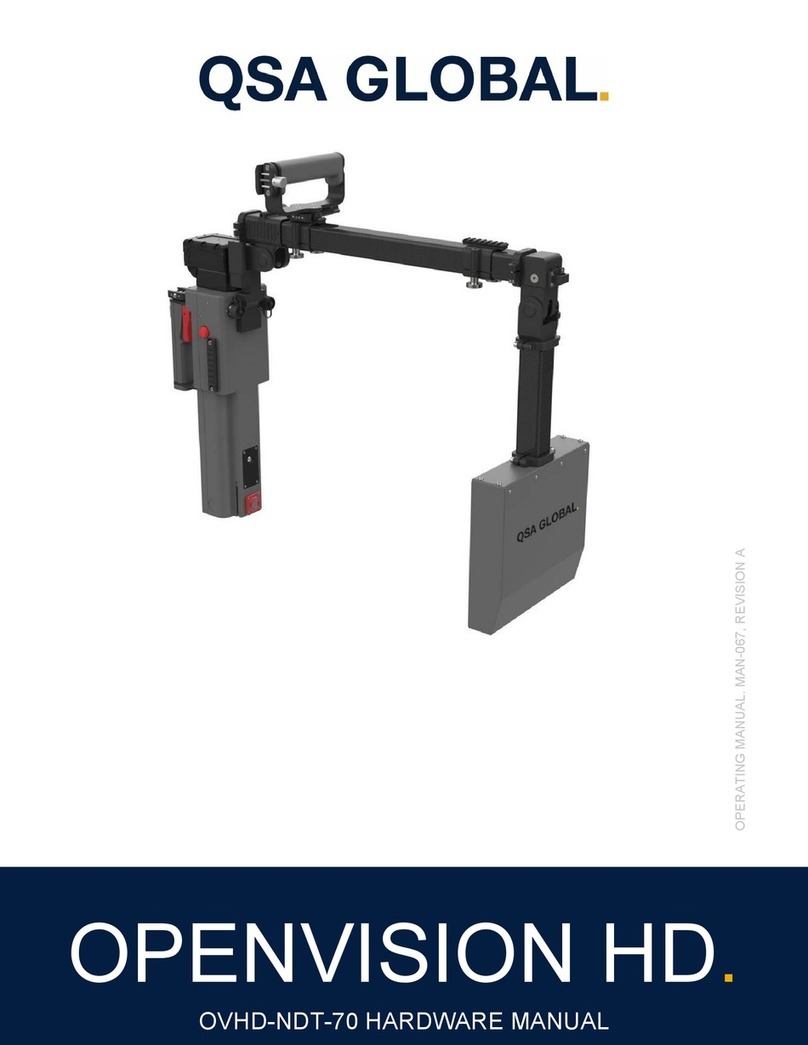
QSA Global OPENVISION HD OVHD-NDT-70 Mounting instructions

SOFTWARE MANUAL. MAN-066, REVISION B
OPENVISION HD.
OVHD-NDT-70 SOFTWARE MANUAL

QSA Global, Inc. 40 North Avenue Burlington, MA 01803 888.272.2242 781.272.2000 qsa-global.com
Software Manual MAN-066 March 2023 Page 2 of 43
Revision Record
Date Description
A 03/2023 Production Release
B 03/2023 Content Revision

QSA Global, Inc. 40 North Avenue Burlington, MA 01803 888.272.2242 781.272.2000 qsa-global.com
Software Manual MAN-066 March 2023 Page 3 of 43
Openvision HD Software.
Power Cycling
Each OpenVision™ HD unit utilizes an embedded microprocessor to handle and coordinate all aspects of safety and normal
operating functions. With such a system, it requires several seconds to initialize before starting normal operations. Following
the Startup and Shutdown sequences below is critical for normal operation; (Figure 1) for key and indicator locations.
Startup
When the Controller Key is turned to its ON position, the CPU indicator will immediately turn on (green). A boot up screen
will be displayed during initialization, and the System Status Indicators will also illuminate. When these indicators turn green
and the Home Screen (Figure 2) is displayed, system startup is complete and ready for normal operation.
Shutdown
Turning the Controller Key to its OFF position will begin the shutdown sequence. The Status Indicator Lights will turn off
after one to three seconds, but the system will not be fully powered down until the CPU Power Indicator LED is turned off.
Once off, remove the key, and place the unit in storage. No additional cool down is required.
CAUTION: FAILURE TO ALLOW THE SYSTEM TO PROPERLY SHUTDOWN MAY CORRUPT INTERNAL MEMORY,
AND UNIT MAY NOT BE ABLE TO RESTART.
Home Screen
The Home Screen (Figure 2) displays the output of the targeting camera (outlined in red) and the Settings menu across the
bottom (outlined in yellow).
System Status
Indicator
Controller
Key (ON)
CPU Power
Indicator
Figure 1 Indicators and Power Switch Details

QSA Global, Inc. 40 North Avenue Burlington, MA 01803 888.272.2242 781.272.2000 qsa-global.com
Software Manual MAN-066 March 2023 Page 4 of 43
Figure 2 Home Screen
Settings Menu
The Settings menu will always be displayed when the Home Screen is active. On the Home Screen, the Settings menu is
inactive (i.e. unable to change values) by default. The Settings menu can be activated from either the Home Screen or the
X-Ray Imaging Screen by holding the hat switch down for three seconds (Figure 3).
Figure 3 Hat Switch
When the X-Ray voltage becomes highlighted in yellow (Figure 4), the Settings menu is active, and can be navigated using
the hat switch’s left/right positions. Up/down positions change the value of the highlighted setting.
The Settings menu becomes disabled when the hat switch is in its neutral (center) position for 15 seconds.
Note: While the Settings menu is active, the hat switch cannot be used to navigate to another screen.

QSA Global, Inc. 40 North Avenue Burlington, MA 01803 888.272.2242 781.272.2000 qsa-global.com
Software Manual MAN-066 March 2023 Page 5 of 43
Figure 4 Active Settings Menu
Table 1 shows the settings and user adjustable values available in the Settings menu:
Table 1 Settings Menu Parameters
Setting (Units) Possible Values
X-Ray Voltage (kV) Low, Medium, High (default Low)
X-Ray Current (mA) Low, Medium, High (default Low)
The Settings menu also displays the following system information on the right-hand side:
System date and time
Software version
Current battery level (OpenVision HD)
X-Ray tube temperature
OpenVision
TM
HD online status indicator

QSA Global, Inc. 40 North Avenue Burlington, MA 01803 888.272.2242 781.272.2000 qsa-global.com
Software Manual MAN-066 March 2023 Page 6 of 43
Firing X-Rays
Figure 5 X-Ray Warning Screen
The Trigger Handle shown in Figure 6 is a positionally adjustable fixture that allows the user to grip the machine, fire X-rays, and
take snapshots and video recordings.
Trigger Handle: Hold the red trigger to begin firing X-rays. Release the trigger to stop firing X-rays. The Snapshot
Button can then be pressed as need while X-rays continue to fire. You can take an image by pressing and releasing
the button or take a video by pressing for two seconds and then releasing. The video will continue to record until
the button is pressed again. If the operator’s hand is removed from the Trigger Handle, X-rays will stop firing.
System will transition to the X-Ray Warning Screen (Figure 5) for five seconds, during which the buzzer will pulse at one-
second intervals. The System Status Indicators (on either side of main housing) will also turn amber.
Figure 6 Trigger Switch Options

QSA Global, Inc. 40 North Avenue Burlington, MA 01803 888.272.2242 781.272.2000 qsa-global.com
Software Manual MAN-066 March 2023 Page 7 of 43
X-Ray Live Image Screen
After five seconds of holding the X-ray trigger, the system will begin emitting X-Rays, and transition to the X-Ray Live Image
Screen (Figure 7; Settings menu is hidden by default). System Status Indicators remain amber-colored, and the buzzer
pulse rate changes to two-second intervals.
Figure 7 X-Ray Live Image Screen
To change settings while emitting X-Rays, hold down the hat switch for three seconds (Figure 3) to show and activate the
Settings menu (Figure 8).
Figure 8 Settings Menu Re-activated
The X-Ray Live Image Screen remains active until the red trigger button is released or 90 seconds has elapsed. When
either occurs, the following will happen:
System stops emitting X-rays
Buzzer turns off

QSA Global, Inc. 40 North Avenue Burlington, MA 01803 888.272.2242 781.272.2000 qsa-global.com
Software Manual MAN-066 March 2023 Page 8 of 43
System Status Indicators turn green
Home Screen is displayed
Image Capture
An image (or snapshot) can be captured from either the Home Screen (targeting camera image) or the X-Ray Live Image
Screen (X-Ray image). Snapshots are taken by pressing and releasing the Snapshot Button on either the system or Trigger
Handle (Figure 9).
Figure 9 Snapshot Button Options
The system will display the snapshot in the upper left-hand corner (Picture-in-Picture) of the current screen for five seconds
(Figure 10) and is automatically saved to internal storage in PNG image format.
Figure 10 Image Capture Retained (upper left corner)

QSA Global, Inc. 40 North Avenue Burlington, MA 01803 888.272.2242 781.272.2000 qsa-global.com
Software Manual MAN-066 March 2023 Page 9 of 43
Video Capture
Like snapshots, videos can be recorded from either the Home Screen (targeting camera image) or the X-Ray Live Image
Screen (X-Ray image). Videos are taken by pressing and holding the Snapshot Button for at least two seconds. Within one
second, the system will commence recording video, indicated by a notification 'Recording in progress...' appearing in the
upper right-hand corner of the display (Figure 11). After two seconds, the operator can release the capture button. When
the button is pressed again, the recording stops and is automatically saved to internal storage in MPEG4 video format.
Figure 11 X-Ray Video Recording in Progress
Custom Naming Media Files
Media Files (video and snapshots) can be given a name of choice to act as an identifier that will display within the image. A
filename can be set before recording images, and videos. The name will increment numerically as more images are
captured. (Ex: “Image1”, “Image2”,etc.). This allows for the creation a collection of image captures in an alpha-numerical
sequence to identify a select body of work.
To set a Custom Naming sequence, press right on the toggle switch for five seconds. A keyboard menu will appear on the
monitor (Figure 12). Use the toggle switch to navigate to the desired letter/number. Press the Snapshot button to select
each character. When finished, select “Apply”. The monitor will then return to the main screen. The system is now ready
to record Images/Videos with the custom name. When the system is shutdown the filename sequence will return to its
default value.
QSA Global, Inc. 40 North Avenue Burlington, MA 01803 888.272.2242 781.272.2000 qsa-global.com
Software Manual MAN-066 March 2023 Page 10 of 43
Figure 12 File Naming Sequence Selection Screen
System Information
The System Information Screen (Figure 13) is accessible from the Home Screen (and with the Settings menu inactive) by
holding the hat switch in the left position for three seconds. The System Info Screen includes:
X-ray tube temperature
X-ray tube cycle count
Approximate number of images system’s internal storage can hold (Storage Available)
Current system date and time (can be modified)
Access to Admin Screen
Image, Video Playback
Manage Media
This menu is navigated by the hat switch’s left/right positions. Up/down positions change the value of the highlighted setting.
On-screen buttons (e.g., Apply) are actuated with the Snapshot Button (Figure 9). Exit transitions back to the Home Screen.
Figure 13 System Info Screen

QSA Global, Inc. 40 North Avenue Burlington, MA 01803 888.272.2242 781.272.2000 qsa-global.com
Software Manual MAN-066 March 2023 Page 11 of 43
Video Playback
(System Info Screen, Figure 13) brings up the Playback Selection Screen (Figure 14). Image directories
(if any) are shown on this screen, labeled by date. Newest directories are displayed first. Selecting the on-screen
button shows additional folders (if any). Select desired folder to view playback videos or images. As always, the Snapshot
Button (Figure 9) actuates on-screen buttons/folders.
Left/right hat switch positions navigate between images/videos within an image folder. The hat switch’s down position exits
image playback mode.
The organization of images on the OpenVision HD is by directories that are named with a date stamp of the format
'YYYYMMDD'. If the directory does not exist at the point the first snapshot for the day is taken, the directory will be
automatically created. Images within the directory are named in the format 'YYYYMMDD-HHMMSS.png' to ensure that
unique names are created for each image taken.
Figure 14 Playback Selection Screen
USB Drive Configuration for Media Transfer
USB drives must be configured before images/videos can be transferred from the OpenVision HD system. A properly
configured USB drive includes an 'ov2' directory at the drive’s top-level, and an 'images' directory within the 'ov2' directory
(see Figure 15). Unless these directories are on the USB drive as indicated, the software will not transfer images/videos.
CAUTION: TO ENSURE THAT THE USB DRIVE DOES NOT BECOME CORRUPTED, ALWAYS WAIT UNTIL THE
SYSTEM TRANSITIONS BACK TO THE HOME SCREEN (Figure 2) BEFORE REMOVING THE USB DRIVE FROM
OPENVISION HD.

QSA Global, Inc. 40 North Avenue Burlington, MA 01803 888.272.2242 781.272.2000 qsa-global.com
Software Manual MAN-066 March 2023 Page 12 of 43
Figure 15 USB Drive Folder Format

QSA Global, Inc. 40 North Avenue Burlington, MA 01803 888.272.2242 781.272.2000 qsa-global.com
Software Manual MAN-066 March 2023 Page 13 of 43
Image Transfer
Inserting a properly configured (Figure 15) USB drive in the external USB port (Figure 16) of the OpenVision HD transitions to
the Media Transfer Screen (Figure 17). Navigate to desired folder to copy, then press and release the Snapshot Button
(Figure 9) to initiate file transfer.
Figure 16 USB Port
Figure 17 Media Transfer Screen
When no image directories are found on the OpenVision HD, the message “No Images to transfer” message (Figure 18)
will be displayed. Selecting [Cancel] will transition to the Home Screen and the USB drive can then be safely removed.

QSA Global, Inc. 40 North Avenue Burlington, MA 01803 888.272.2242 781.272.2000 qsa-global.com
Software Manual MAN-066 March 2023 Page 14 of 43
Figure 18 No Images Present
When one or more image directories are found, the Media Transfer Screen (Figure 17) will appear displaying up to four
buttons at one time with names of the directories that exist on the OpenVision HD. To select a directory for transfer, navigate
to the desired date stamp button and select the button. This will transition the user to the Image Transfer Confirmation
Screen (Figure 19).
NOTICE: Only one directory of images will be transferred to the USB drive per insertion. Following the last step of a transfer
the screen will transition to the home screen. To initiate another transfer, remove the USB drive from the OpenVision
HD
and reinsert.
Figure 19 Image Transfer Confirmation
Figure 19 presents the user with Yes and No to confirm the image transfer. Selecting No will transition to the Home Screen
and the USB drive may be safely removed. Selecting Yes will transition to the Transfer in Progress Screen (Figure 20). No
user action is required. The amount of time this screen is displayed is determined by the number of images in the image
directory. At the completion of the transfer, the system will transition to the Image Deletion Confirmation Screen (Figure 21).

QSA Global, Inc. 40 North Avenue Burlington, MA 01803 888.272.2242 781.272.2000 qsa-global.com
Software Manual MAN-066 March 2023 Page 15 of 43
Figure 20 Transfer in Progress
Figure 21 presents the user with Yes and No to confirm the image deletion for the selected date. Selecting No will transition
to the Home Screen and the USB drive may be safely removed (no images will be deleted from the OpenVision
HD).
Selecting Yes will cause the images in that specified folder to be deleted from the OpenVision HD and then the system will
transition to the Home Screen.
Figure 21 Image Deletion Confirmation
When the user has confirmed the image transfer, the software performs a check to determine if there is enough space on
the USB drive to hold all the images contained in the selected folder. If there is insufficient space, this screen will be
displayed (Figure 22). Selecting the Close button will cause the system to transition to the Home Screen and the USB drive
can be safely removed.

QSA Global, Inc. 40 North Avenue Burlington, MA 01803 888.272.2242 781.272.2000 qsa-global.com
Software Manual MAN-066 March 2023 Page 16 of 43
Figure 22 Insufficient Space Warning
Admin Password Screen
Selecting the Admin in the System Info Screen (Figure 13) transitions to the Admin Password Screen (Figure 23). The hat
switch’s left/ right positions navigate between Enter, Exit, and the password digits. Pressing Exit will transition back to the
Home Screen. If the correct password has been entered, selecting Enter transitions to the Admin Screen.
Figure 23 Admin Password Screen

QSA Global, Inc. 40 North Avenue Burlington, MA 01803 888.272.2242 781.272.2000 qsa-global.com
Software Manual MAN-066 March 2023 Page 17 of 43
System Administration
In the Admin Screen (Figure 24), use the hat switch’s left/right positions to navigate between settings, and the up/down
positions to change the highlighted setting. Settings that can be changed and their value ranges are shown in Table 3.
Select to save any changes. Otherwise, select . Either action will transition back to the Home
Screen.
Figure 24 Admin Screen
Table 2 Admin Screen Settings
Admin Screen Setting Possible values*
V
olta
g
e, Low
(
kV
)
40 - 70 kV
V
olta
g
e, Medium
(
kV
)
40 kV to 70 kV
V
olta
g
e, Hi
g
h
(
kV
)
40 kV to 70 kV
Voltage, Super (kV) 40 kV to 70 kV
Current, Low 0.090 m
A
to 0.300 m
A
Current, Medium 0.090 m
A
to 0.300 m
A
Current, Hi
g
h 0.090 m
A
to 0.300 m
A
Current, Super 0.090 m
A
to 0.300 m
A
Super Mode Enable/Disable
Require Scatter Shield Enable/Disable
Admin Password 0000-9999
Factor
y
Reset Resets OpenVision HD to factor
y
settin
g
s
Ethernet Server Enable/Disable
Remote Power Control Enable/Disable
V
ideo Stitchin
g
Enable/Disable
*Power is limited to 12 W (kV x mA) max. (e.g., 70 kV @ .171 mA = 12 W, 40 kV @ .300 mA = 12 W)

QSA Global, Inc. 40 North Avenue Burlington, MA 01803 888.272.2242 781.272.2000 qsa-global.com
Software Manual MAN-066 March 2023 Page 18 of 43
Super Mode
Super Mode provides the ability for fine control of voltage and current settings while on the Home Screen and during
operation of the OpenVision HD. With Super Mode enabled, the operator can adjust (through the settings menu) voltage in
1 kV increments and current in .001 mA increments.
The Admin Screen’s Super Mode (Figure 24) must be checked. Once the user selects the on-screen
button the user interface will return to the Home Screen and both kV and mA in the settings menu will indicate Super (Figure
25). Activate the Settings menu (Settings Menu section beginning on page 4) and navigate to either the kV or mA setting.
Pressing the up/down hat switch will change the value highlighted.
Figure 25 Home Screen with Super Mode Enabled

QSA Global, Inc. 40 North Avenue Burlington, MA 01803 888.272.2242 781.272.2000 qsa-global.com
Software Manual MAN-066 March 2023 Page 19 of 43
OpenVision Wi-Fi Tablet.
Figure 26 OpenVision HD Wi-Fi Table
Startup and Power Down of Tablet
The OpenVision
TM
HD tablet is a touch screen tablet. To power up, press the power button on the tablet’s upper-left corner.
The OpenVision HD APP will automatically launch on power up. To power down the tablet, press the Home Screen’s power
button (Figure 27). Press the Okay button to verify shutdown.
Figure 27 Software Power Button

QSA Global, Inc. 40 North Avenue Burlington, MA 01803 888.272.2242 781.272.2000 qsa-global.com
Software Manual MAN-066 March 2023 Page 20 of 43
Home Screen
The home screen (Figure 28) is divided into three main sections: Viewing window (center), Settings menu (bottom, outlined
in yellow), and Control Panel which can be user-selected to appear on the left or right side (shown on right, outlined in red).
Figure 28 OpenVision HD APP Home Screen
Establishing Wi-Fi Connection, Link, and Streaming
Tablet will automatically connect to Wi-Fi direct when the APP launches, which may take a few seconds. The Wi-Fi symbol
will show “Connected” when a Wi-Fi connection has been established (Figure 29).
Figure 29 OpenVision HD Wi-Fi Connected
Other manuals for OPENVISION HD OVHD-NDT-70
1
Table of contents
Other QSA Global Industrial Equipment manuals

QSA Global
QSA Global OPENVISION HD OVHD-NDT-70 User manual

QSA Global
QSA Global OPENVISION DX OVDX-NDT-70 Mounting instructions

QSA Global
QSA Global OPENVISION DX OVDX-NDT-70 User manual

QSA Global
QSA Global OPENVISION DX User manual

QSA Global
QSA Global SENTINEL SENTRY 330 User manual

QSA Global
QSA Global OPENVISION DX OVDX-NDT-70 User manual