manuals.online logo
Brands
  1. Home
  2. •
  3. Brands
  4. •
  5. QSC
  6. •
  7. Speakers System
  8. •
  9. QSC SC-433 User manual

QSC SC-433 User manual

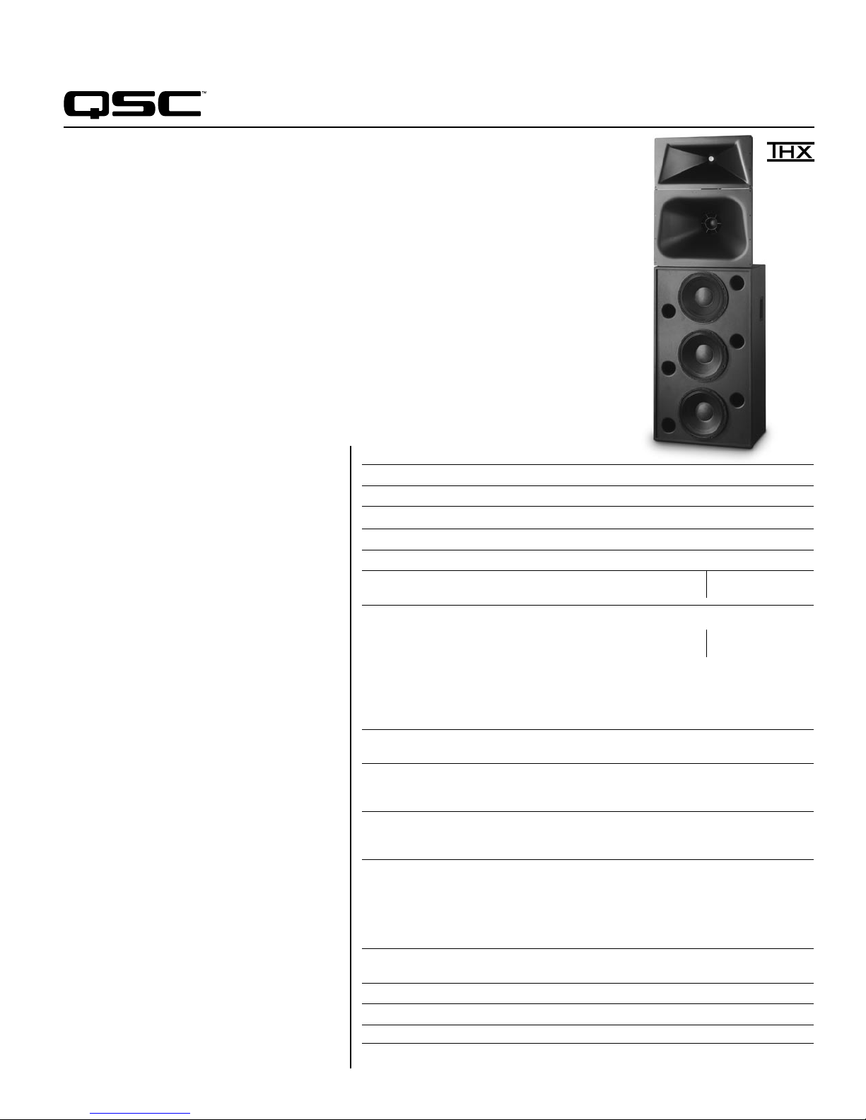
Developed specifically for the unique requirements
of professional motion picture playback, the SC-433
extends QSC’s commitment to the cinema market. As
a member of the DCS Digital Cinema Speaker Series,
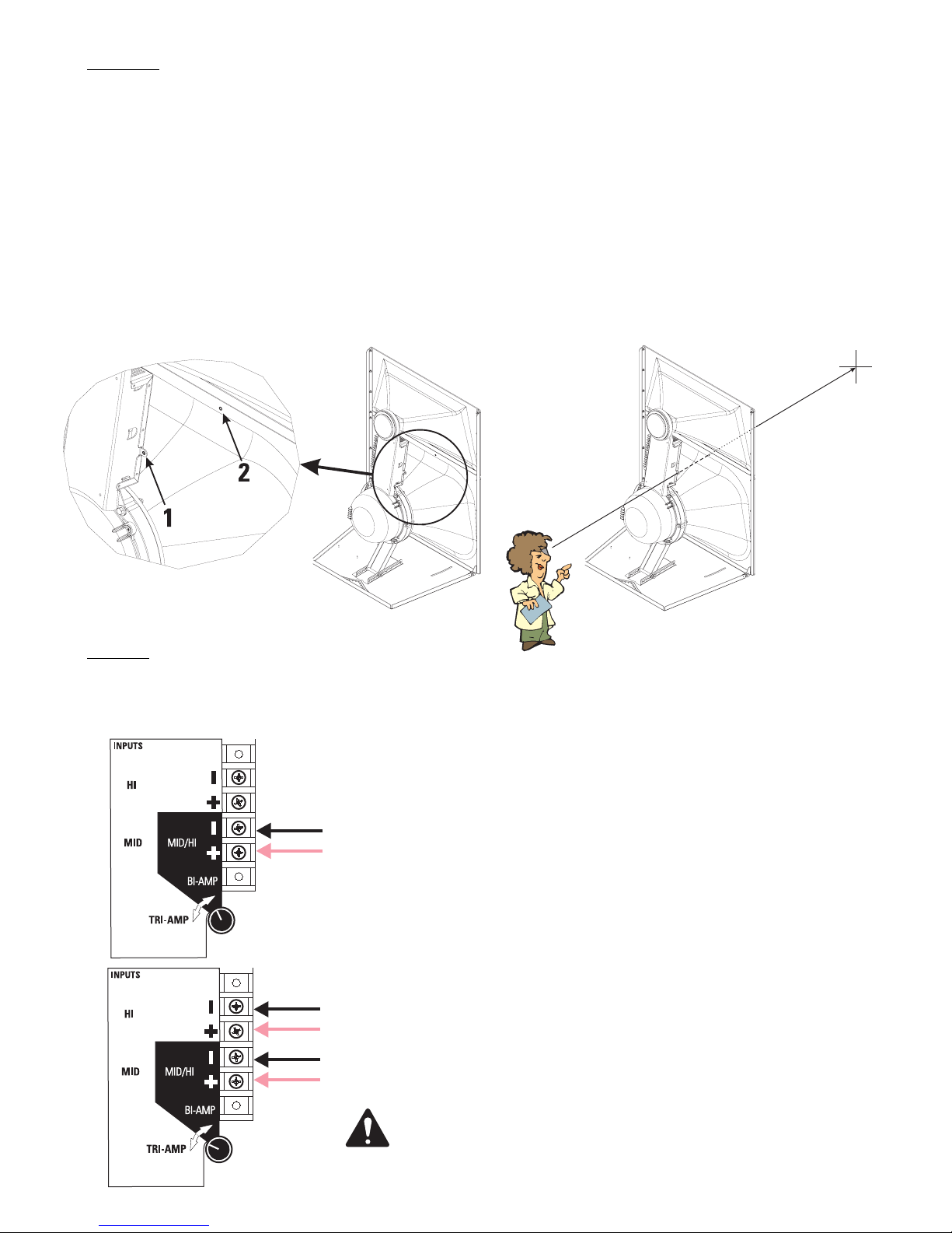
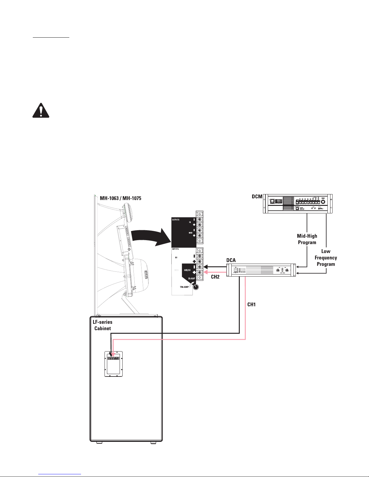
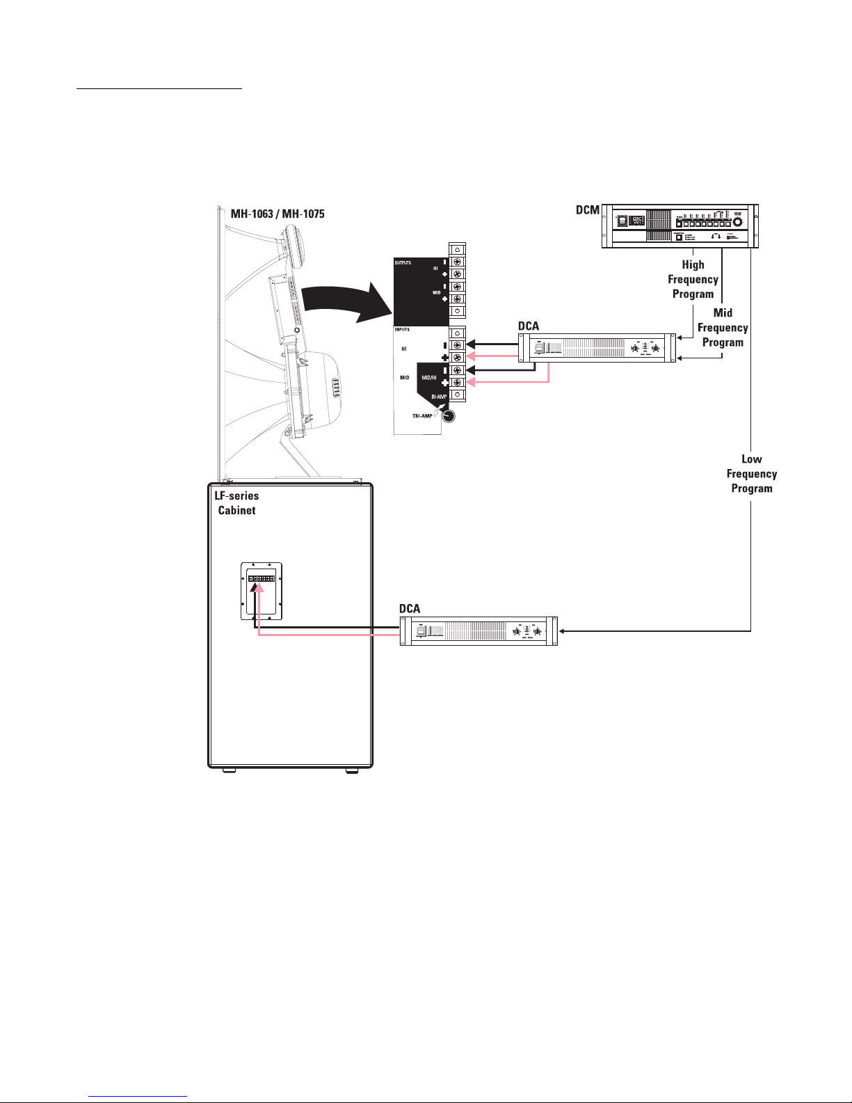
the SC-433 is a three-way, selectable bi or tri-amplified
screen channel loudspeaker system comprised of two
main units—the MH-1075 high-frequency system and
the LF-4315 low-frequency system.
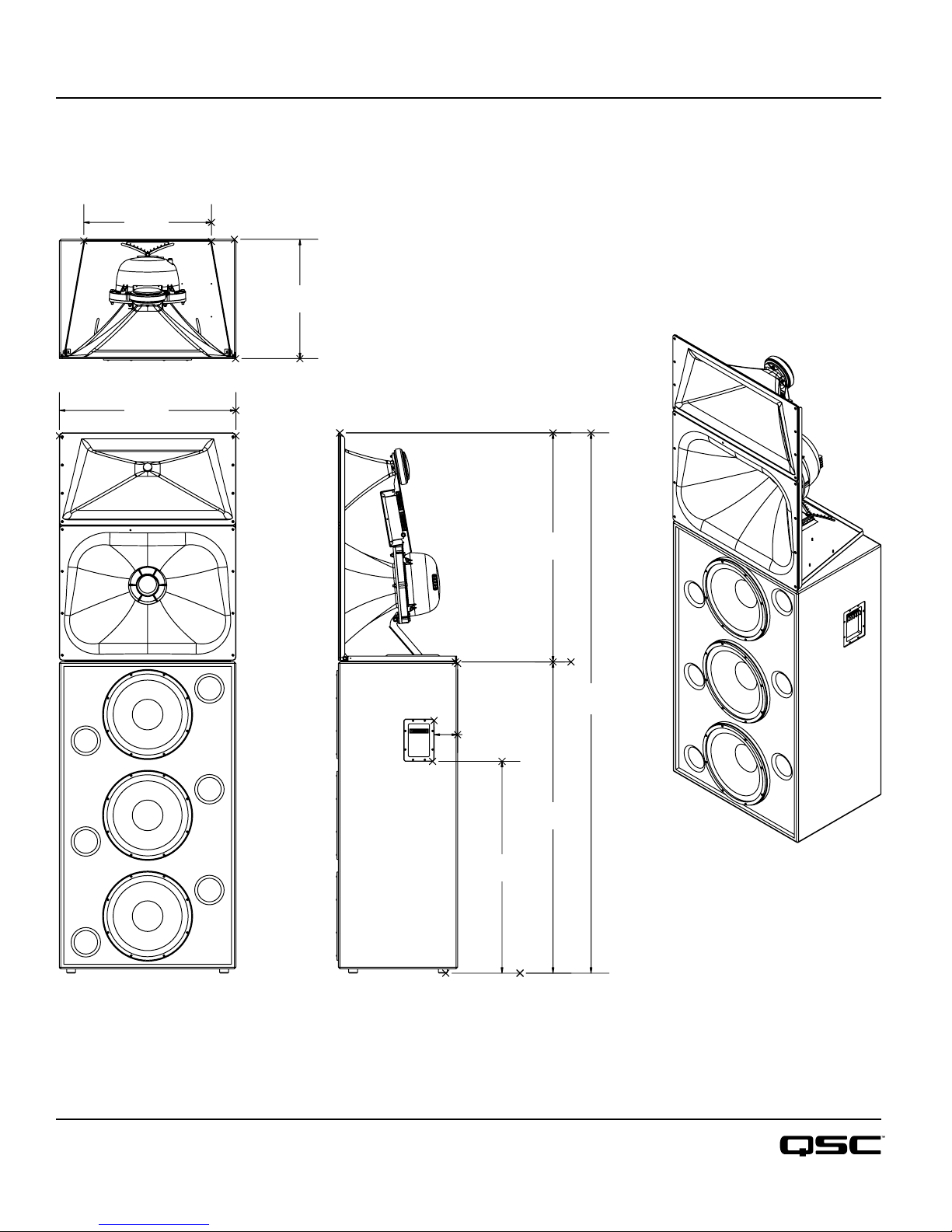
The MH-1075 mid-high system features a high
output, horn loaded 10"midrange cone driver and a
3"(75mm) titanium diaphragm compression driver
mounted to an adjustable pan and tilt bracket. The
MH-1075 includes a driver protection network and
a passive crossover for bi-amp operation. Power
limiter circuitry protects the high-frequency driver
from overpowering. The MH-1075 provides extended
frequency coverage for the critical midrange band. A
high power 10"cone driver allows operation as low
as 250 Hz and the advanced phase plug coupling
permits a crossover point of up to 1800 Hz to the
high-frequency horn. This ensures that most of the
dialog range is reproduced by a single element, for
unmatched intelligibility.
The LF-4315 triple 15"(381mm) low-frequency
enclosure is designed specifically to address the
extended low-frequency response required for cinema
applications. The LF-4315 covers the frequency range
from 35 Hz to 250 Hz. Close Coupled Woofers
(CCW), with their tight spacing between woofers,
improves coupling and keeps coverage angles wide
over a greater frequency range than more widely
spaced designs.
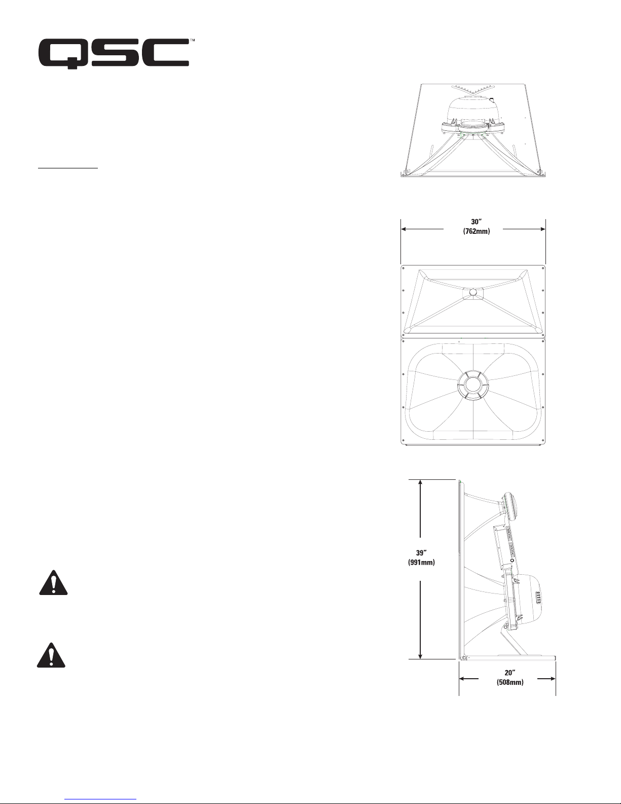
The SC-433 is designed for ease of installation.
The MH-1075 components come pre-assembled to
reduce field assembly time. Three bolts are all that
are required to secure the MH-1075 to the top of the
LF-4315 enclosure.
SC-433
Cinema Loudspeaker System
Specifications SC-433
Nominal Coverage 90° horizontal x +20 to -30° vertical
Frequency Range 32 Hz - 16 kHz (-6 dB)
Crossover Frequency 250 and 1700 Hz, 24 dB per octave
LF-4315 MH-1075
Impedance 5.5Ω8Ω
Sensitivity 1 watt /1 meter, 99.5 dB Bi-amp Tri-amp
half space 105 dB MF 105 dB HF 107.5 dB
Maximum Input Power1
8 hours of 6 db crest factor 1200 W RMS 250 W RMS2275 W RMS 80 W RMS
IEC 268 noise spectrum
2 hours of 6 db crest factor 1500 W RMS 350 W RMS
pink noise, 50 Hz - 20 kHz,
AES method
Recommended Amplifier Power 2400 W RMS maximum 800 W RMS maximum
Recommended Processing Subsonic filter below 30 Hz, 4th order LR crossover at 200 and
> 18 dB per octave 1700 Hz via QSC DCM or QSControl.net
Connectors Barrier strip screw terminals Barrier strip screw terminals
accept up to #10 AWG accept up to #10 AWG stranded wire
stranded wire
Transducers Three 15" (381mm) high efficiency, 10" high efficiency mid range,
extended bass woofer featuring 1.5" (38mm) exit, 3" titanium
4" copper voice coils diaphragm compression driver
Enclosure Quasi B4 alignment, ported Tilt/Pan Bracket
enclosure with fully flared ports, ±10° vertical tilt
symmetrical port design, tuned to ±10° horizontal pan
36 Hz, constructed of MDF and
heavily braced. Features vandal
resistant woofer mounting bolts
Dimensions (HWD) 53" x 30" x 20.3" 39" x 30" x 20"
(1344 mm x 762 mm x 516 mm) (990 mm x 762 mm x 508 mm)
Weight - Net 260 lbs (118 kg) 85 lbs (39 kg)
System Weight 345 lbs (157 kg)
Baffle Cut-Out 93" x 32"
1) Maximum input power tested in accordance with IEC 268-5 recommendations, 50 Hz - 20 kHz band limiting, 6 dB signal crest factor.
2) Maximum input power tested in accordance with IEC 268-5 recommendations, 200 Hz - 2 kHz band limiting, 6 dB signal crest factor.
passive
mid-high
Features
• Three-way selectable, bi or tri- amplified screen channel system
• MH-1075 provides 90° horizontal by +20° to -30° vertical coverage
• LF-4315 is constructed of MDF and features single woofer chambers
• Low-distortion waveguides provide highly articulate dialogue
• Shallow depth (20") facilitates installation
• THX™ approved for professional cinema applications
THX is a trademark of THX Ltd.
SC-433 Dimensions
qscaudio.com
Specifications subject to change without notice.
1675 MacArthur Boulevard • Costa Mesa, CA 92626 • Ph: 800/854-4079 or 714/957-7100 • Fax: 714/754-6174
SC-433 Spec Sheet - 03/10/06
Top
Side
21.7"
551 mm
20.3"
516 mm
30"
762 mm
Front
92"
2337 mm
36"
914 mm
39"
990 mm
53"
1346 mm
4"
102 mm
*TD-000180-00*
Cinema Mid-High Loudspeaker System User Manual
MH-1063 10” (254mm) mid, 2.5” (63mm) compression driver
MH-1075 10” (254mm) mid, 3.0” (75mm) compression driver
Introduction
The MH-1063 and MH-1075 “mid-high packs” provide the mid and high frequency
components of three-way screen channel loudspeaker systems for high performance
cinema applications. They were designed to operate with and be directly mounted on
QSC’s cinema low frequency enclosures.
Mid frequencies are reproduced with a 10” (254mm) high-efficiency, phase-ring
loaded driver mounted on a custom designed cinema horn. The high-frequency driver
is a large format, 2.5” (63mm, MH-1063) or 3.0” (75mm, MH-1075) titanium dia-
phragm compression driver mounted on a custom high-frequency cinema horn. The
high frequency horn is a low-distortion waveguide providing highly articulate dialogue
without coloration associated with conventional horn loudspeakers. Both horns fea-
ture broad horizontal and vertical coverage angles to ensure coverage of every seat in
the auditorium. The driver assemblies are mounted on an adjustable pan and tilt
bracket that has an integral aiming sight, simplifying installation.
The MH-1063 and MH-1075 loudspeakers include a driver protection and crossover
network to assure reliable operation. DC blocking capacitors protect against DC or
low-frequency signals that could damage an unprotected driver. Power limiter circuitry
protects the driver from over-powering and an 18dB/octave crossover seamlessly
blends the high and mid frequency elements. Outboard processing is required to form
the crossover between the LF and MH loudspeakers.
Bi-amp or tri-amp operation is possible using a selector switch mounted on the con-
nections panel. The bi-amp setting provides a passive crossover network between mid
and high drivers. Separate amplifiers and an active crossover are required for the low
frequency channel and the mid-high channel. Tri-amp setting disables the internal
mid-high crossover and each driver is driven independently by its own amplifier and
active crossover; one for the low, one for the mid, and one for the high frequencies.
The MH-1063 and MH-1075 components come pre-assembled to reduce field assem-
bly time. Three bolts are all that are required to secure the mid-high assembly to the
top of a QSC low frequency enclosure.
Install in accordance with QSC Audio Product’s instructions and a
licensed, professional engineer. Only use attachments, mounts,
accessories, or brackets specified by QSC Audio Products, Inc. Refer
all servicing to qualified personnel. Servicing is required when the
apparatus has been damaged in any way.
WARNING! Before placing, installing, rigging, or suspending any
speaker product, inspect all hardware, suspension, cabinets, trans-
ducers, brackets and associated equipment for damage. Any missing,
corroded, deformed or non-load rated component could significantly
reduce the strength of the installation, placement, or array. Any such
condition severely reduces the safety of the installation and should
be immediately corrected. Use only hardware which is rated for the
loading conditions of the installation and any possible short-term
unexpected overloading. Never exceed the rating of the hardware or
equipment. Consult a licensed, professional engineer when any
doubt or questions arise regarding a physical equipment installation. TD-000180-00 rev.A
© Copyright 2004, QSC Audio Products, Inc.
QSC® is a registered trademark of QSC Audio Products, Inc.
“QSC” and the QSC logo are registered with the U.S. Patent and Trademark Office
1675 MacArthur Blvd., Costa Mesa, CA, 92626 USA
Main Number (714) 754-6175 Sales & Marketing (714) 957-7100 or toll free (USA only) (800) 854-4079
Customer Service(714) 957-7150 or toll free (USA only) (800) 772-2834
2
Settings
BI-AMP / TRI-AMP Operating Mode Selection
Set the operating mode selector switch to BI-AMP or TRI-AMP, depending on your application setup.
Mounting
Attaching to Low Frequency Enclosure
The mid-high loudspeaker assembly attaches to the top of the QSC low frequency cabinet with three 5/16-18 bolts, 0.75” long, with
lock washers. This hardware ships installed on the low frequency cabinet. We recommend the use of serviceable thread locking com-
pound when installing the bolts to prevent loosening due to vibration. Do not fully tighten the mounting hardware before aiming (see
below).
Aiming
Aim the horn in the horizontal plane (pan) before tightening the attachment hardware. Adjust the vertical tilt with the mid-high vertical
adjustment bracket. The mid-high assembly is equipped with an aiming sight to assist in achieving desired coverage quickly and easily.
For typical applications, the aim point should be the center seat in the back row of the auditorium. If the cinema screen has already
been installed, a flashlight placed at the desired aiming point can be seen through the screen perforations in a darkened auditorium.
Where the sight holes are located: How to use the sights:
Aim point:
BI-AMP-When set to BI-AMP, the MH-1063 and MH-1075 accepts mid-
high frequency signals on one set of inputs and uses an internal crossover
network between the mid- and high-frequency drivers. The signal applied
to the mid-high loudspeaker assembly must not contain low-frequency
content (below 200 Hz).
TRI-AMP- When set to TRI-AMP, the MH-1063 and MH-1075 accepts
separate mid- and high-frequency signals on two sets of inputs. The inter-
nal crossover network is bypassed and only the protective circuitry for the
H.F. driver remains. Each of the driver’s signals must have the appropriate
signal processing before operating.
Do not connect amplifiers directly to the driver inputs!
Always use the input terminal strip.
3
Connections
INPUT Terminals
The MH-1063 and MH-1075 have barrier strip screw terminals that accept up to #10 AWG (5.3mm2) stranded loudspeaker wire.
Observe proper polarity. Use the largest wire size and shortest wire length for the application.
OUTPUT Terminals
The OUTPUT terminals are factory-connected to the drivers. These terminals should ONLY be connected to their respective driver. Do
not connect signals to these terminals as all protection and equalization circuitry will be bypassed.
NOTE! Maintain proper loudspeaker connection polarity throughout the entire system for maximum performance.
Do not apply full range signal to the MH-1063 / MH-1075! There is a mid-high passive crossover for bi-amp mode
only. There is no crossover connected when operating in tri-amp mode. A protection network is always active. All
required signal processing must be done before the signal is applied to the loudspeaker. Do not connect any sig-
nal to the upper sets of OUTPUT terminals.
BI-AMP mode connections- Ensure the mode switch is set to BI-AMP, connect the input to the MH-1063 / MH-1075 to the lower
set of input terminals marked “BI-AMP + -”.
BI-AMP Mode- one
amplifier channel is used
for the low frequency
cabinet and one amplifier
channel for the mid-high
assembly. The MH-1063 /
MH-1075 mode switch is
set to BI-AMP. Active
crossovers are used
before amplification. The
mid-high assembly pro-
vides a passive crossover
between the mid and
high frequency drivers.
4
Connections (continued)
TRI-AMP mode connections- When the mode switch is set to TRI-AMP, connect the high frequency signal to the terminals marked
“INPUT HI + -” and the mid frequency signal to the terminals marked “INPUT MID + -”.
TRI-AMP Mode- one
amplifier channel is
used for the low fre-
quency cabinet, one
amplifier channel for
the mids, and one
amplifier channel for
the high frequencies.
The MH-1063 / MH-
1075 mode switch is
set to TRI-AMP,
bypassing the internal
mid-high passive cross-
over. Active or passive
crossovers are used
before amplification.
Power limiter and DC
blocking remain active.
5
MH-1063 Specifications (subject to change without notice)
Freq. Range 180 - 15k (-6dB, full space)
Nominal Coverage 90° horizontal X +20 to -30° vertical (50° total, adjustable mount provides for vertical plane adjustments.
The horizontal plane can be adjusted by altering mounting position on the low frequency enclosure before
tightening bolts.
DI: 9 dB (400 to 16k Hertz average)
Q: 8 (400 to 16k Hertz average)
Max. Output: [Tri-amp mode] Mid Freq. 135.5 dB SPL calculated peak, 1m, full space
[Tri-amp mode] High Freq. 131.5 dB SPL calculated peak, 1m, full space
[Bi-amp mode] 135 dB SPL calculated peak, 1m ,full space
Impedance: [Bi-amp mode] 8 ohms nominal
7.9 ohms minimum at 1500 Hertz
91 ohms maximum at 150 Hertz
Maximum Input Power [Tri-amp mode] Mid Freq. 275 W (AES method, 2 hrs.)
[Tri-amp mode] High Freq. 60 W (AES method, 2 hrs.)
[Bi-amp mode] 250 W (IEC method, 8 hrs.)
Sensitivity [Tri-amp mode] Mid Freq. 105 dB SPL, 1 watt, 1 meter
[Tri-amp mode] High Freq. 107.5 dB SPL, 1 watt, 1 meter
[Bi-amp mode] 135 dB SPL, 1 watt, 1 meter
Crossover Frequency [Tri-amp mode] 250 Hertz or higher, 24dB/octave and 1.7k Hertz, 24dB/octave
[Bi-amp mode] 250 Hertz or higher, 24dB/octave
Crossover Network 1.7k Hertz, 18 dB/octave electrical slope, HF driver power limiting circuit (never disrupts continuity). Swit-
chable operation between Bi-Amp and Tri-amp operation. Tri-amp setting removes crossover circuit from
signal, leaving power limiter and DC blocking capacitors.
Connectors Barrier strip screw terminals accept up to #10 AWG stranded wire. Four terminals, two HF input and two
MF input (for Tri-amp mode operation).
Transducers MF: 10" high efficiency midrange, phase-ring loaded.
HF: 1.5" (38mm) exit, 2.5" (63.5mm) titanium diaphragm compression driver.
Mounting Hardware: Attaches to top of the low frequency cabinet using three 5/16”-18 x 3/4” long bolts.
Size 39” high x 30” wide x 20” deep (991 x 762 x 508mm)
Weight 85 lb. (39 kg) net
6
MH-1075 Specifications (subject to change without notice
Freq. Range 180 - 15k (-6dB, full space)
Nominal Coverage 90° horizontal X +20 to -30° vertical (50° total, adjustable mount provides for vertical plane adjustments.
The horizontal plane can be adjusted by altering mounting position on the low frequency enclosure before
tightening bolts.
DI: 9 dB (400 to 16k Hertz average)
Q: 8 (400 to 16k Hertz average)
Max. Output: [Tri-amp mode] Mid Freq. 135.5 dB SPL calculated peak, 1m, full space
[Tri-amp mode] High Freq. 133 dB SPL calculated peak, 1m, full space
[Bi-amp mode] 135.5 dB SPL calculated peak, 1m ,full space
Impedance: [Bi-amp mode] 8 ohms nominal
6.4 ohms minimum at 1500 Hertz
91 ohms maximum at 150 Hertz
Maximum Input Power [Tri-amp mode] Mid Freq. 275 W (AES method, 2 hrs.)
[Tri-amp ode] High Freq. 80 W (AES method, 2 hrs.)
[Bi-amp mode] 250 W (IEC method, 8 hrs.)
Sensitivity [Tri-amp mode] Mid Freq. 105 dB SPL, 1 watt, 1 meter
[Tri-amp mode] High Freq. 108 dB SPL, 1 watt, 1 meter
[Bi-amp mode] 135.5 dB SPL, 1 watt, 1 meter
Crossover Frequencies [Tri-amp mode] 250 Hertz or higher, 24dB/octave and 1.7k Hertz, 24dB/octave
[Bi-amp mode] 250 Hertz or higher, 24dB/octave
Crossover Network 1.7k Hertz, 18 dB/octave electrical slope, HF driver power limiting circuit (never disrupts continuity). Swit-
chable operation between Bi-Amp and Tri-amp operation. Tri-amp setting removes crossover circuit from
signal, leaving power limiter and DC blocking capacitors.
Connectors Barrier strip screw terminals accept up to #10 AWG stranded wire. Four terminals, two HF input and two
MF input (for Tri-amp mode operation).
Transducers MF: 10" high efficiency midrange, phase-ring loaded.
HF: 1.5" (38mm) exit, 3" (76mm) titanium diaphragm compression driver.
Mounting Hardware: Attaches to top of the low frequency cabinet using three 5/16”-18 x 3/4” long bolts.
Size 39” high x 30” wide x 20” deep (991 x 762 x 508mm)
Weight 85 lb. (39 kg) net
7
MH-1075 SPL and Impedance vs. Frequency
SPL (dB)
Frequency (Hertz)
Impedance (Ohms)
Impedance
SPL
MH-1063 SPL and Impedance vs. Frequency
SPL
Impedance
SPL (dB)
Frequency (Hertz)
Impedance (Ohms)
Warranty (USA only; other countries, see your dealer or distributor)
Disclaimer
QSC Audio Products, Inc. is not liable for any damage to amplifiers, or any other equipment that is caused by negligence or
improper installation and/or use of this loudspeaker product.
QSC Audio Products 3 Year Limited Warranty
QSC Audio Products, Inc. (“QSC”) guarantees its products to be free from defective material and / or workmanship for a period
of three (3) years from date of sale, and will replace defective parts and repair malfunctioning products under this warranty
when the defect occurs under normal installation and use - provided the unit is returned to our factory or one of our authorized
service stations via pre-paid transportation with a copy of proof of purchase (i.e., sales receipt). This warranty provides that
the examination of the return product must indicate, in our judgment, a manufacturing defect. This warranty does not extend
to any product which has been subjected to misuse, neglect, accident, improper installation, or where the date code has been
removed or defaced. QSC shall not be liable for incidental and/or consequential damages. This warranty gives you specific
legal rights. This limited warranty is freely transferable during the term of the warranty period.
Customer may have additional rights, which vary from state to state.
In the event that this product was manufactured for export and sale outside of the United States or its territories, then this lim-
ited warranty shall not apply. Removal of the serial number on this product, or purchase of this product from an unauthorized
dealer, will void this limited warranty. Periodically, this warranty is updated. To obtain the most recent version of QSC’s war-
ranty statement, please visit www.qscaudio.com. Contact us at 800-854-4079 or visit our website at www.qscaudio.com.
Contacting QSC Audio Products
Mailing address:QSC Audio Products, Inc.
1675 MacArthur Boulevard
Costa Mesa, CA 92626-1468 USA
Telephone Numbers:
Main Number (714) 754-6175
Sales & Marketing (714) 957-7100 or toll free (USA only) (800) 854-4079
Customer Service(714) 957-7150 or toll free (USA only) (800) 772-2834
Facsimile Numbers:
Sales & Marketing Fax(714) 754-6174
Customer Service Fax(714) 754-6173
World Wide Web:www.qscaudio.com
E-mail:[email protected]
[email protected]
QSC Audio Products, Inc. 1675 MacArthur Boulevard Costa Mesa, California 92626 USA
©2004 “QSC” and the QSC logo are registered with the U.S. Patent and Trademark Office.
*TD-000177-00*
Cinema Loudspeaker Systems User Manual
LF-4315 Low Frequency Loudspeaker
Introduction
The LF-4315 15” (381mm) low frequency enclosure is designed specifically for cinema appli-
cations. Meeting cinema requirements for extended low frequency response differentiates
the LF-4315 from more conventional “rock-and-roll” woofer systems. The LF-4315 covers the
frequency range from 30 Hertz to 500 Hertz, depending upon the high frequency system
requirements.
The three custom 400 watt, 15” transducers were developed specifically for cinema use.
They feature 4” (100mm) voice coils, 120 oz.(3.4kg) ceramic magnets, and multi-vented pole
pieces to ensure cool operation. Cooler temperatures increase transducer lifespan and
decrease power compression at high power levels. Undercut pole pieces ensure the voice
coils operate in symmetrical magnetic gaps, reducing second order harmonic distortion. The
suspension and voice coils of the transducers have been designed to provide low distortion
and high impact bass at high power.
The enclosure is constructed of high quality medium density fiberboard panels with stiffen-
ing braces on all panels. Both internal and external port openings are fully radiused ensuring
smooth air flow at higher power levels, preventing audible port turbulence.
Bass ports are symmetrically spaced on each side of the transducers, making internal pres-
sure more uniform across the back surface of the transducers. This prevents the cones from
being displaced to one side or another by unbalanced forces, reducing the chance of driving
the voice coils out of the center of the gaps at high power.
Three T-nuts in the top of the enclosure provide easy mounting of QSC’s HF-75 high fre-
quency system, or MH-1075 mid-high system.
Enclosure is not designed to be suspended, flown, or rigged. Do not sus-
pend, fly, or rig this enclosure.
This product is capable of producing sound pressure levels that can perma-
nently damage human hearing. Always keep sound pressure levels in the
listening area below levels that can damage human hearing.
Install in accordance with QSC Audio Product’s instructions and a
licensed, professional engineer. Only use attachments, mounts, accesso-
ries, or brackets specified by QSC Audio Products, Inc. Refer all servicing
to qualified personnel. Servicing is required when the apparatus has been
damaged in any way.
WARNING! Before placing, installing, rigging, or suspending any speaker
product, inspect all hardware, suspension, cabinets, transducers, brackets
and associated equipment for damage. Any missing, corroded, deformed or
non-load rated component could significantly reduce the strength of the
installation, placement, or array. Any such condition severely reduces the
safety of the installation and should be immediately corrected. Use only
hardware which is rated for the loading conditions of the installation and
any possible short-term unexpected overloading. Never exceed the rating
of the hardware or equipment. Consult a licensed, professional engineer
when any doubt or questions arise regarding a physical equipment installa-
tion.
TD-000177-00 rev.C
© Copyright 2004, QSC Audio Products, Inc.
QSC® is a registered trademark of QSC Audio Products, Inc.
“QSC” and the QSC logo are registered with the U.S. Patent and Trademark Office
1675 MacArthur Blvd., Costa Mesa, CA, 92626 USA
Main Number (714) 754-6175 Sales & Marketing (714) 957-7100 or toll free (USA only) (800) 854-4079
Customer Service (714) 957-7150 or toll free (USA only) (800) 772-2834
Mounting points for
high or mid-high
system
Connections
Normal Connection
The LF-4315 has barrier strip screw termi-
nals for connection. The terminals accept
up to #10 AWG (5.3mm2) stranded loud-
speaker wiring. Use the largest wire size
and shortest wire length possible for a
given installation. Observe the polarity
markings and keep polarity consistent
throughout the system for best perfor-
mance.
Parallel Connection of Second LF-4315
The terminals marked OUTPUT may be
used to connect another LF-4315 in paral-
lel. Connect the wires as shown in the illus-
tration, at right.
Normal Connection Example:
Parallel Connection Example:
Amplifier capable of
driving 5.5 ohm loads
Amplifier capable of
driving 2.75 ohm loads
LF-4315 Specifications (subject to change without notice)
Frequency Range: 32 - 1200 Hertz (-6dB)
28 - 2800 Hertz useable range (-10dB)
Nominal Coverage: 125° horizontal X 60° vertical at 315 Hertz
Maximum Output:
136.0dB SPL calculated peak, 1 meter, half space, at rated rms power with 6 dB crest factor pink noise input, 35 - 1000 Hertz.
130.0dBA SPL calculated maximum continuous, 1 meter. The dBA scale is typically used to identify sound sources
which can cause permanent hearing loss.
Impedance: 5.5 ohms nominal
4.5 ohms minimum, 150 Hertz
30 ohms maximum, 22 Hertz
Maximum Input Power: 1200 watts rms (8 hours of 6dB crest factor pink noise, 40 - 400 Hertz)
1500 watts rms (2 hours of 6dB crest factor pink noise, 40 - 400 Hertz)
recommended amplifier power capability- 2400 watts rms maximum into 4 ohms (per LF-4315)
Sensitivity: 99.0dB half space, 98.0dB full space, 35 - 1000 Hertz, 1 watt, 1 meter
Recommended Processing: Subsonic filter below 25 Hertz, >18 dB per octave, maximum recommended crossover frequency is 500 Hertz. QSC DSP
configurations are available at www.qscaudio.com. Parameters for alternative processing hardware are available upon
request.
Connectors: Barrier strip screw terminals accept up to #10 AWG (5.3mm2) stranded wire. Four terminals: (two INPUT and two par-
allel OUTPUT).
Transducers: Three 15” (381mm) high efficiency low frequency transducer featuring vented 4” (100mm) copper voice coil on Kap-
ton® formers. High excursion/low distortion design, with extremely high power handling, and low thermal compres-
sion.
Enclosure: Quasi B4 alignment, ported enclosure with fully flared ports, low turbulence symmetrical port design, tuned to 34
Hertz, constructed of medium density fiberboard and heavily braced. Features vandal resistant woofer mounting bolts.
Size: 30” wide X 53” high X 20” deep (762mm X 1321mm X 508mm)
Weight: 290 lbs. shipping, 260 lbs. net (132/118 kg.)
SPL and Impedance vs. Frequency
Frequency (Hertz)
SPL (dB)
Impedance (ohms)
SPL 2pi
Impedance
SPL 4pi
Warranty (USA only; other countries, see your dealer or distributor)
Disclaimer
QSC Audio Products, Inc. is not liable for any damage to amplifiers, or any other equipment that is caused by negligence or
improper installation and/or use of this loudspeaker product.
QSC Audio Products 3 Year Limited Warranty
QSC Audio Products, Inc. (“QSC”) guarantees its products to be free from defective material and / or workmanship for a period
of three (3) years from date of sale, and will replace defective parts and repair malfunctioning products under this warranty
when the defect occurs under normal installation and use - provided the unit is returned to our factory or one of our authorized
service stations via pre-paid transportation with a copy of proof of purchase (i.e., sales receipt). This warranty provides that
the examination of the return product must indicate, in our judgment, a manufacturing defect. This warranty does not extend
to any product which has been subjected to misuse, neglect, accident, improper installation, or where the date code has been
removed or defaced. QSC shall not be liable for incidental and/or consequential damages. This warranty gives you specific
legal rights. This limited warranty is freely transferable during the term of the warranty period.
Customer may have additional rights, which vary from state to state.
In the event that this product was manufactured for export and sale outside of the United States or its territories, then this lim-
ited warranty shall not apply. Removal of the serial number on this product, or purchase of this product from an unauthorized
dealer, will void this limited warranty. Periodically, this warranty is updated. To obtain the most recent version of QSC’s war-
ranty statement, please visit www.qscaudio.com. Contact us at 800-854-4079 or visit our website at www.qscaudio.com.
Contacting QSC Audio Products
Mailing address:QSC Audio Products, Inc.
1675 MacArthur Boulevard
Costa Mesa, CA 92626-1468 USA
Telephone Numbers:
Main Number (714) 754-6175
Sales & Marketing (714) 957-7100 or toll free (USA only) (800) 854-4079
Customer Service(714) 957-7150 or toll free (USA only) (800) 772-2834
Facsimile Numbers:
Sales & Marketing Fax(714) 754-6174
Customer Service Fax(714) 754-6173
World Wide Web:www.qscaudio.com
E-mail:[email protected]
[email protected]
QSC Audio Products, Inc. 1675 MacArthur Boulevard Costa Mesa, California 92626 USA
©2004 “QSC” and the QSC logo are registered with the U.S. Patent and Trademark Office.
Kapton® is a registered trademark of E.I. du Pont de Nemours and Company.
Manual del usuario de los sistemas de altavoces para salas de cine
Altavoz de baja frecuencia LF-4315
Introducción
La caja de baja frecuencia de 15” (381 mm) del altavoz LF-4315 está diseñada específica-
mente para aplicaciones cinematográficas. El cumplimiento de los requisitos de las aplica-
ciones cinematográficas referentes a una respuesta extendida de baja frecuencia, es lo que
distingue al altavoz LF-4315 de otros sistemas woofer tipo “rock-and-roll” más convenciona-
les. El altavoz LF-4315 cubre un intervalo de frecuencia de 30 Hertzios a 500 Hertzios, depen-
diendo de los requisitos del sistema de alta frecuencia.
Los tres transductores adaptados de 400 vatios y 15” se desarrollaron específicamente para
su uso en salas de cine. Cuentan con bobinas de voz de 4” (100 mm), imanes cerámicos de
120 onzas (3.4 kg) y polos multiventilados para asegurar una operación fría. Las temperatu-
ras más frías aumentan la vida útil del transductor y reducen la compresión de la potencia a
niveles altos de potencia. Los polos proyectados aseguran que las bobinas de voz operen en
campos magnéticos simétricos, reduciendo la deformación armónica de segundo orden. La
suspensión y las bobinas de voz de los transductores se han diseñado para brindar una baja
distorsión y graves de alto impacto a alta potencia.
La caja está construida de paneles de cartón duro mediano de alta calidad con soportes de
refuerzo en todos los paneles. Ambas aberturas del puerto, la interna y la externa, están
totalmente redondeadas, lo cual asegura un flujo de aire uniforme a mayores niveles de
potencia, evitando turbulencia audible en el puerto.
Los puertos de graves están separados simétricamente a cada lado de los transductores,
haciendo que la presión interna sea más uniforme a través de la superficie posterior de los
transductores. Esto evita que los conos sean desplazados de un lado a otro por fuerzas no
equilibradas, reduciendo la probabilidad de impulsar las bobinas de voz fuera del centro de
los espacios a altos niveles de potencia.
Tres tuercas en T en la parte superior de la caja permiten el montaje fácil del sistema de alta
frecuencia HF-75 o del sistema de frecuencia media alta MH-1075, ambos de QSC.
La caja no esta diseñada para montarse suspendida, en voladizo ni sobre
arneses. No suspenda esta caja, no la monte en voladizo ni sobre arneses.
Este producto es capaz de producir niveles de presión del sonido que
pueden causar daños permanentes al oído humano. Siempre mantenga los
niveles de presión del sonido en un área de audición con un nivel menor
que el que provoca daños al oído humano.
Instale de acuerdo con las instrucciones de QSC Audio Products y de un
ingeniero profesional con la debida licencia. Sólo use piezas, montajes,
accesorios y soportes especificados por QSC Audio Products, Inc. Refiera
todo el servicio a personal calificado. Cuando el aparato haya sido dañado
de alguna manera, es necesario proporcionarle servicio.
¡ADVERTENCIA! Antes de colocar, instalar, montar o suspender cualquier
producto de altavoz, inspeccione todo el equipo físico, la suspensión, los
armarios, los transductores, los soportes y el equipo asociado para detec-
tar la existencia de daños. Cualquier componente faltante, corroído, defor-
mado, o sin carga nominal podría reducir significativamente la resistencia
de la instalación, la colocación o la configuración. Cualquier condición de
este tipo reduce gravemente la seguridad de la instalación y debe corre-
girse de inmediato. Use sólo herraje que esté clasificado para las condi-
ciones de carga de la instalación y cualquier posible carga excesiva a
corto plazo inesperada. Nunca exceda el valor nominal del equipo físico ni
del dispositivo. Consulte a un ingeniero profesional con la debida licencia
cuando surjan dudas o preguntas referentes a la instalación física del
equipo.
1675 MacArthur Blvd., Costa Mesa, CA, 92626 EE.UU.
Número principal +1 (714) 754-6175 Ventas y Comercialización +1 (714) 957-7100
o línea sin costo (sólo para EE.UU.) +1 (800) 854-4079
Servicio al cliente +1 (714) 957-7150 o gratis (sólo EE.UU.) +1 (800) 772-2834
Puntos de montaje para
el sistema de alta fre-
cuencia o el sistema de
frecuencia media alta
TD-000177-00 rev. C
© Derechos de autor 2004, QSC Audio Products, Inc.
QSC® es una marca comercial registrada de QSC Audio Products, Inc.
“QSC” y el logotipo de QSC están registrados con la Oficina de Patentes y Marcas
Comerciales de los Estados Unidos
Conexiones
Conexión normal
El altavoz LF-4315 tiene terminales de tor-
nillo de barra protectora para su conexión.
Los terminales aceptan cableado trenzado
de hasta #10 AWG (5.3 mm2) para altav-
oces. Use el alambre del calibre más
grande y de la longitud más corta posible
en cualquier instalación. Observe las mar-
cas de polaridad y mantenga la polaridad
uniforme en todo el sistema para permitir
el mejor rendimiento.
Conexión en paralelo de un segundo LF-
4315
Los terminales marcados SALIDA se
pueden usar para conectar en paralelo otro
altavoz LF-4315. Conecte los cables como
se muestra en la ilustración, a la derecha.
Ejemplo de una conexión normal:
Ejemplo de conexión en paralelo:
Amplificador con
capacidad de accio-
namiento de cargas
de 5.5 ohmios
Amplificador con
capacidad de acciona-
miento de cargas de
2.75 ohmios
Especificaciones del sistema LF-4315 (sujetas a cambio sin previo aviso)
Intervalo de frecuencias: 32 - 1200 Hertzios (-6dB)
Intervalo utilizable de 28 -2800 Hertzios (-10 dB)
Cobertura nominal: 125° horizontal X 60° vertical a 315 Hertzios
Salida máxima:
Pico calculado de SPL: 136.0 dB, 1 metro, medio espacio, a una potencia rms nominal con entrada de ruido rosa con factor de
cresta de 6 dB, 35 - 1000 Hertzios.
Máximo calculado continuo de SPL: 130.0 dBA, 1 metro. La escala de dBA típicamente se usa para identificar
fuentes de sonido que pueden causar pérdida auditiva permanente.
Impedancia: 5.5 ohmios, nominal
4.5 ohmios mínimo, 150 Hertzios
30 ohmios máximo, 22 Hertzios
Potencia máxima 1200 vatios rms (8 horas de ruido rosa con factor de cresta de 6 dB, 40 - 400 Hertzios)
de entrada: 1500 vatios rms (2 horas de ruido rosa con factor de cresta de 6 dB, 40 - 400 Hertzios)
Capacidad recomendada de potencia del amplificador: 2400 vatios rms como máximo en 4 ohmios (por LF-4315)
Sensibilidad: 99.0 dB medio espacio, 98.0 dB espacio completo, 35 - 1000 Hertzios, 1 vatio, 1 metro
Procesamiento Filtro subsónico menor de 25 Hertzios, >18 dB por octava, la frecuencia máxima de cruce recomendada es de 500
recomendado: Hertzios. Las configuraciones DSP de QSC están disponibles en www.qscaudio.com. Los parámetros para el her-
raje de procesamiento alternativo están disponibles si así se solicitan.
Conectores: Los terminales de tornillo de barra protectora aceptan alambre trenzado de hasta #10 AWG (5.3 mm2). Cuatro ter-
minales: (dos de ENTRADA y dos de SALIDA paralela).
Transductores: Tres transductores de baja frecuencia de alta eficiencia, de 15” (381 mm), con bobina de voz de cobre de 4” (100
mm) ventilada, en soportes de Kapton®. Diseño de alta excursión/baja deformación, con un manejo de potencia
extremadamente alta, y baja compresión térmica.
Caja: Alineación Quasi B4, caja con puertos totalmente abocinados, diseño de puerto simétrico de baja turbulencia,
afinado a 34 Hertzios, construido de cartón duro de media densidad y fuertemente soportado. Tiene pernos de
montaje del woofer resistentes al vandalismo.
Tamaño: 30” de ancho X 53” de alto X 20” de profundidad (762 mm X 1.321mm X 508 mm)
Peso: 290 libras envío, 260 libras neto (132/118 kg.)
SPL e impedancia en función de la frecuencia
Frecuencia (hertzios)
SPL (dB)
Impedancia (ohmios)
SPL 2pi
Impedancia
SPL 4pi
Garantía (sólo para EE.UU.; para otros países, consulte con su vendedor o distribuidor)
Renuncia de responsabilidad
QSC Audio Products, Inc. no es responsable por ningún daño a los amplificadores, ni a ningún otro equipo que sea causado por
negligencia o instalación y/o uso inadecuado de este altavoz.
Garantía limitada de 3 años de QSC Audio Products
QSC Audio Products, Inc. (“QSC”) garantiza que sus productos estarán libres de materiales y/o mano de obra defectuosos por
un periodo de tres (3) años a partir de la fecha de la venta, y reemplazará las piezas defectuosas y reparará los productos que
funcionen mal bajo esta garantía cuando el defecto ocurra bajo condiciones normales de instalación y uso, siempre y cuando
la unidad se devuelva a nuestra fábrica o a una de nuestras estaciones autorizadas de servicio mediante transportación prep-
agada con una copia del comprobante de compra (por ejemplo, el recibo de la compra). Esta garantía requiere que el examen
del producto devuelto indique, en nuestra opinión, un defecto de fabricación. Esta garantía no se extiende a ningún producto
que hubiera estado sometido a uso indebido, negligencia, accidente, instalación incorrecta, o en el que se hubiera quitado o
modificado el código de la fecha. QSC tampoco será responsable por daños incidentales y/o emergentes. Esta garantía le
otorga derechos legales específicos. Esta garantía limitada es libremente transferible durante el período de la misma.
El cliente podría gozar de derechos adicionales, que podrían variar de un estado a otro.
En caso de que este producto fuera fabricado para exportación y venta fuera de los Estados Unidos o sus territorios, entonces
no será aplicable esta garantía limitada. La eliminación del número de serie en este producto, o la compra de este producto de
un distribuidor no autorizado, anularán esta garantía limitada. Esta garantía se actualiza periódicamente. Para obtener la ver-
sión más reciente de la declaración de la garantía de QSC, por favor visite www.qscaudio.com. Comuníquese con nosotros al
800-854-4079 o visite nuestro sitio en Internet en www.qscaudio.com.
Cómo comunicarse con QSC Audio Products
Dirección postal:QSC Audio Products, Inc.
1675 MacArthur Boulevard
Costa Mesa, CA 92626-1468 EE.UU.
Números de teléfono:
Número principal +1 (714) 754-6175
Ventas y comercialización +1 (714) 957-7100 o gratis (sólo EE.UU.) +1 (800) 854-4079
Servicio al cliente +1 (714) 957-7150 o gratis (sólo EE.UU.) +1 (800) 772-2834
Números de fax:
Fax de ventas y comercialización +1 (714) 754-6174
Fax de servicio al cliente +1 (714) 754-6173
World Wide Web:www.qscaudio.com
Correo electrónico:[email protected]
[email protected]
QSC Audio Products, Inc. 1675 MacArthur Boulevard Costa Mesa, California 92626 EE.UU.
©2004, “QSC” y el logo QSC están registrados con la Oficina de Patentes y Marcas Comerciales de EE.UU.
Kapton® es una marca comercial registrada de E.I. du Pont de Nemours and Company.
Manuel d'utilisation de systèmes de haut-parleurs de cinéma
Haut-parleur basse fréquence LF-4315
Introduction
L'enceinte basse fréquence de 381 mm LF-4315 a été tout spécialement conçue pour les
applications en salle de cinéma. Les exigences des cinémas en matière de réponse longue durée
basse fréquence différencient le LF-4315 des systèmes de haut-parleurs de graves « rock-and-
roll » plus conventionnels. Le LF-4315 couvre la plage de fréquence de 30 à 500 Hz, selon les
exigences de haute fréquence du système.
Les trois transducteurs personnalisés de 38 cm et 400 W ont été spécialement développés pour
un usage en salles de cinéma. Ils ont des bobines mobiles de 100 mm, des aimants en céramique
de 4,4 kg et des pôles à évents multiples pour empêcher la surchauffe. Les températures
inférieures augmentent la durée de vie des transducteurs et diminuent la compression de
puissance à de hauts niveaux de puissance. Les pôles évidés garantissent le fonctionnement des
bobines mobiles dans un espace magnétique symétrique, ce qui réduit la distorsion harmonique
secondaire. La suspension et les bobines mobiles des transducteurs visent à produire une faible
distorsion et des graves à fort impact à haute puissance.
L'enceinte est faite de panneaux de fibres de densité moyenne et de haute qualité avec des
renforts sur tous les panneaux. Les ouvertures internes et externes des ports sont entièrement
arrondies, garantissant la circulation d'air uniforme à haute puissance, ce qui empêche les
turbulences sonores.
Les ports à basses sont équidistants de part et d'autre des transducteurs, ce qui répartit
uniformément la pression interne à travers la surface arrière des transducteurs. Ceci empêche le
déplacement des cônes d'un côté ou de l'autre par des forces déséquilibrées, ce qui réduit le
risque d'excentrage des bobines mobiles à haute puissance.
Trois écrous en T sur le dessus de l'enceinte facilitent la fixation du système haute fréquence
HF-75 ou du système sonore de hauteur moyenne MH-175 de QSC.
L'enceinte n'a pas été conçue pour être suspendue, balancée ou montée.
La suspension, le balancement ou le montage de l'enceinte sont interdits.
Ce produit est capable de produire des niveaux de pression sonore
susceptibles d'endommager l'ouïe de manière irréversible. Toujours
maintenir les niveaux de pression sonore dans la zone d'écoute en deçà de
niveaux susceptibles de compromettre l'ouïe.
Installer conformément aux instructions de QSC Audio Products et d'un
technicien professionnel diplômé. Utiliser uniquement des fixations,
supports, accessoires ou équerres spécifiés par QSC Audio Products.
Confier toutes les réparations à un personnel qualifié. Une réparation ou
maintenance est requise lorsque l'appareil a été endommagé d'une
manière quelconque.
AVERTISSEMENT ! Avant de placer, installer, monter ou suspendre un haut-
parleur, inspecter l'état de toute la visserie, du matériel de suspension, des
armoires, des transducteurs, des supports et du matériel associé. Tout
composant manquant, corrodé, déformé ou non adapté à la charge risque
de réduire sensiblement la solidité de l'installation, sa mise en place ou sa
portée. Une telle condition réduit sensiblement la sécurité de l'installation
et doit être immédiatement corrigée. Utiliser uniquement du matériel de
montage prévu pour les conditions de charge de l'installation et toute
surcharge éventuelle à court terme imprévue. Ne jamais dépasser les
spécifications nominales du matériel de montage ou de l'équipement.
Consulter un technicien professionnel diplômé en cas de doute ou de
question concernant l'installation physique de l'équipement.
TD-000177-00 rév.C
© Copyright 2004, QSC Audio Products, Inc.
QSC® est une marque déposée de QSC Audio Products, Inc.
QSC et le logo QSC sont des marques déposées auprès de l'U.S. Patent and
Trademark Office.
1675 MacArthur Blvd., Costa Mesa, CA 92626
Téléphone (standard) +1 (714) 754-6175 Ventes et Marketing +1 (714) 957-7100
ou +1 (800) 854-4079 (numéro vert valable aux États-Unis seulement)
Service clientèle +1 (714) 957-7150 ou numéro vert (États-Unis seulement) +1 (800) 772-2834
Points de fixation d'un
système haute
fréquence ou de
hauteur moyenne
Branchements
Branchement normal
Le branchement du LF-4315 se fait à partir de
bornes vissables de bornier à cloisons. Les
bornes acceptent des câbles de haut-parleurs
toronnés pouvant atteindre #10 AWG
(5,3 mm2). Utiliser le calibre de conducteur
maximal et la longueur de conducteur
minimale, dans la mesure du possible, pour
toute installation. Observer les repères de
polarité et maintenir une polarité constante à
travers le système pour une meilleure
performance.
Branchement en parallèle d'un second
LF-4315
Les bornes marquées OUTPUT peuvent
servir au branchement d'un autre LF-4315 en
parallèle. Brancher les conducteurs comme
indiqué sur l'illustration, à droite.
Exemple de branchement normal :
Exemple de branchement en parallèle :
Amplificateur
capable de piloter
des charges de
5,5 ohms
Amplificateur capable
de piloter des charges
de 2,75 ohms

Other manuals for SC-433

1

Other QSC Speakers System manuals

QSC MH-1063 User manual

QSC

QSC MH-1063 User manual

QSC SC-413 User manual

QSC

QSC SC-413 User manual

QSC MH-1060 Series User manual

QSC

QSC MH-1060 Series User manual

QSC SC-312 User manual

QSC

QSC SC-312 User manual

QSC MH-1063 User manual

QSC

QSC MH-1063 User manual

QSC HF-63X2 User manual

QSC

QSC HF-63X2 User manual

QSC SC-323 User manual

QSC

QSC SC-323 User manual

QSC CP Series User manual

QSC

QSC CP Series User manual

QSC LF-4215 User manual

QSC

QSC LF-4215 User manual

QSC HF-75B User manual

QSC

QSC HF-75B User manual

QSC SR-110 User manual

QSC

QSC SR-110 User manual

QSC SC-424 User manual

QSC

QSC SC-424 User manual

QSC ALK-MD2 User manual

QSC

QSC ALK-MD2 User manual

QSC K series User manual

QSC

QSC K series User manual

QSC KLA12 User manual

QSC

QSC KLA12 User manual

QSC SC-324 User manual

QSC

QSC SC-324 User manual

QSC AcousticDesign AD-S6T User manual

QSC

QSC AcousticDesign AD-S6T User manual

QSC AD-S802T User manual

QSC

QSC AD-S802T User manual

QSC HF-63 User manual

QSC

QSC HF-63 User manual

QSC AF218-sw User manual

QSC

QSC AF218-sw User manual

QSC SC-413H User manual

QSC

QSC SC-413H User manual

QSC LF-3115 User manual

QSC

QSC LF-3115 User manual

QSC EB2082-i User manual

QSC

QSC EB2082-i User manual

QSC KW181 User manual

QSC

QSC KW181 User manual

Popular Speakers System manuals by other brands

Polk Mono Signa S1 quick start guide

Polk Mono

Polk Mono Signa S1 quick start guide

Atlantic Technology AW-424 instruction manual

Atlantic Technology

Atlantic Technology AW-424 instruction manual

Sharp AN-28SP2 Instruction

Sharp

Sharp AN-28SP2 Instruction

LG LAS550H Simple manual

LG

LG LAS550H Simple manual

Sony WHG-SLK2iV operating instructions

Sony

Sony WHG-SLK2iV operating instructions

Sven MS-305 Operation manual

Sven

Sven MS-305 Operation manual

Sony SS-CR300 Specifications

Sony

Sony SS-CR300 Specifications

Wohler AMP2-V2DA user manual

Wohler

Wohler AMP2-V2DA user manual

Real-El S-210 Operation manual

Real-El

Real-El S-210 Operation manual

Panasonic SC-NE5DB quick guide

Panasonic

Panasonic SC-NE5DB quick guide

Eagle Arion ET-AR304-BK user manual

Eagle

Eagle Arion ET-AR304-BK user manual

Harman Kardon CITATION 5.0 reference guide

Harman Kardon

Harman Kardon CITATION 5.0 reference guide

Altec Lansing ADA305 user guide

Altec Lansing

Altec Lansing ADA305 user guide

Kitsound PARALLAX user manual

Kitsound

Kitsound PARALLAX user manual

Peavey Quadra 10 Specification sheet

Peavey

Peavey Quadra 10 Specification sheet

Sony SS-CT270 Service manual

Sony

Sony SS-CT270 Service manual

SpeakerCraft AIM8 One owner's manual

SpeakerCraft

SpeakerCraft AIM8 One owner's manual

Bose L1 Pro Series Firmware update

Bose

Bose L1 Pro Series Firmware update

manuals.online logo
manuals.online logoBrands
  • About & Mission
  • Contact us
  • Privacy Policy
  • Terms and Conditions

Copyright 2025 Manuals.Online. All Rights Reserved.