manuals.online logo
Brands
  1. Home
  2. •
  3. Brands
  4. •
  5. Quality Machine Tools
  6. •
  7. Power Tools
  8. •
  9. Quality Machine Tools PM-940M User manual

Quality Machine Tools PM-940M User manual

Popular Power Tools manuals by other brands

ISLAND HOPPER Power Egg HT-309 operating instructions

ISLAND HOPPER

ISLAND HOPPER Power Egg HT-309 operating instructions

Sioux Tools SSR6P25 Instructions-parts list

Sioux Tools

Sioux Tools SSR6P25 Instructions-parts list

Makita HM1317C technical information

Makita

Makita HM1317C technical information

ABB Smart Tool + quick start guide

ABB

ABB Smart Tool + quick start guide

Baumr-AG BMJK-24S user manual

Baumr-AG

Baumr-AG BMJK-24S user manual

Bosch Professional GST 18 V-LI S Original instructions

Bosch

Bosch Professional GST 18 V-LI S Original instructions

Ronix RA-2702 quick start guide

Ronix

Ronix RA-2702 quick start guide

Nordson ProBlue user guide

Nordson

Nordson ProBlue user guide

aoyue int6028 instruction manual

aoyue

aoyue int6028 instruction manual

Hitachi CJ 65VA2 Instruction manual and safety instructions

Hitachi

Hitachi CJ 65VA2 Instruction manual and safety instructions

Makita HM1304 instruction manual

Makita

Makita HM1304 instruction manual

Kurtz Ersa Ersa X-TOOL VARIO operating instructions

Kurtz Ersa

Kurtz Ersa Ersa X-TOOL VARIO operating instructions

SCHUNK KSO 65 Installation and operating instruction

SCHUNK

SCHUNK KSO 65 Installation and operating instruction

Harken LokHead 500 user manual

Harken

Harken LokHead 500 user manual

Senco DuraSpin ExTPro installation instructions

Senco

Senco DuraSpin ExTPro installation instructions

Ferm JSM1020 Original instructions

Ferm

Ferm JSM1020 Original instructions

Milwaukee M12 FUEL 2559-20 Operator's manual

Milwaukee

Milwaukee M12 FUEL 2559-20 Operator's manual

EINHELL BT-CD 12/2 operating instructions

EINHELL

EINHELL BT-CD 12/2 operating instructions

manuals.online logo
manuals.online logoBrands
  • About & Mission
  • Contact us
  • Privacy Policy
  • Terms and Conditions

Copyright 2025 Manuals.Online. All Rights Reserved.

1
PM-940M 10-2016 v1.indd
Model PM-940M
6-speed gear head
9-1/2 x 40 inch table
Powered table (X axis)
Powered headstock (Z axis)
Power downfeed version available
Quill DRO & depth stop
Weight (including cast iron stand) 1300 lbs
701 Parkway View Drive
Pittsburgh, PA 15205
Copyright © 2016
Quality Machine Tools, LLC
Heavy duty milling machine
Table
power feed
Coarse downfeed
& power down-
feed (if installed)
Quill DRO
Fine downfeed
Control box
(movable for
best viewing
location)
1.5 HP (1.1 kW)
220 Vac spindle
motor
Z-axis motor
(headstock elevation)
Spindle speed
selection
2
PM-940M 10-2016 v1.indd
PM-940M
FAQ
This manual contains essential safety advice on the proper setup, operation, maintenance, and service
of the PM-940M mill. Failure to read, understand and follow the manual may result in property damage
or serious personal injury.
There are many alternative ways to install and use a milling machine. As the owner of the machine you
are solely responsible for its proper installation and safe use. Consider the material contained in this
manual to be advisory only. Precision Matthews cannot be held liable for injury or property damage during
installation or use, or from negligence, improper training, machine modifications or misuse.
This manual describes PM-940M machines as shipped from June 2016. There may be detail dif-
ferences between your specific machine and the information given here (with little or no impact on
functionality). If you have questions about any aspect of the manual or your machine, please email
us at [email protected]. Your feedback is welcomed.
My mill doesn’t
run
R8 collets won't go
into the spindle
110 Vac power connected?
E-Stop button out?
Power switch IN?
Circuit breaker tripped?
The locating screw could be in
too far. See Section 4, Mainte-
nance.
3
PM-940M 10-2016 v1.indd
Section 1 FEATURES & SPECIFICATIONS
MODEL PM-940M MILLING MACHINE
General information
The PM-940M is a robust “square column” mill designed for day-in, day-out use in the busy model shop. With an
all-up weight of ovr 1300 lbs it can handle far more than the typical small machine, including end mills up to 1-1/4”
and face mills up to 3”. For precise control of cutter depth there is a worm-driven quill downfeed with graduated dial
and DRO, completely independent of headstock up/down position. Two versions of the mill are available, with and
without power downfeed.
The reversible spindle runs in high-quality (ISO355) tapered-roller bearings enclosed in a 3” diameter quill with
coarse and fine downfeed options. An oil-filled gearbox provides 6 spindle speeds from 90 to 1970 rpm. Features
of the headstock include choice of manual or powered elevation on dovetailed ways, ± 90 degree tilt, and a quill
depth stop for drilling operations. The 40” x 9-1/2" table is powered in the X axis by a variable-speed dc motor. Table
movement in both X and Y axes is along scraped dovetailed ways.
Floor plan
4
PM-940M 10-2016 v1.indd
PM-940M SPECIFICATIONS
Dimensions
Weight, machine only 1000 lb net
Weight, cast iron stand 300 lb net
Size, including stand See floor plan
Stand footprint W 18-1/2 in. x D 26-3/4 in.
Tray W 24 in. x D 34 in.
Electrical
Power requirement 220V, 60 Hz, single phase
Full load current
9A, spindle motor only
Motors
Main (spindle) Cap-start induction, 220V 2 HP, 1725 rpm
X-axis (table traverse) Variable speed gear motor, 1A
Z-axis gear motor (elevation) 220V 120W
Headstock
Vertical travel* 20 in.
Left-right tilt 90 degrees clockwise/counter-clockwise
Spindle
Speeds (rpm) Low range 90 to 345, High range 670 to 1970
Internal taper R8
Top end 6 splines, 28 mm OD
Quill travel 5 in.
Quill diameter 3 in.
Spindle nose to table 20-3/4 in., max, 2" min
Spindle centerline to column cover
11 in. to pleated cover
Drawbar
7/16 - 20, 18 mm wrench
Table
Size W 40 in. x D 9-1/2 in.
Surface height over floor, on stand
Approx 34-3/4 in.
Maximum load 400 lb, table-centered, less if overhanging
Leadscrews Acme, inch pitch, 10 tpi
Left-right table traverse (X-axis)* 26 in.
Front-back cross travel (Y-axis)* 12 in.
T-slots (3) 14 mm wide, 80 mm centerlines
* DRO installation may limit these numbers
T-slot dimensions
5
PM-940M 10-2016 v1.indd
Section 2 INSTALLATION
THESE ARE THE MAIN POINTS TO WATCH OUT FOR!
But read the following pages for more information
Handling the mill is at least a two-man job.
Hand-crank the headstock down until the spindle nose is just clear of
the table. Remove the hand crank, and set it aside.
Lifting gear – sling, hoist or forklift – must be rated for at least 1500 lb.
Working location of the mill must allow:
Full left-right travel of the table
Access to the back of the column (Z-axis leadscrew maintenance)
Headroom for the Z-axis motor
Power requirement is 220V, 60Hz, 1φ, 15A circuit protection (spindle
motor only, 9A full load).
Extension cord not recommended; if no alternative, use 12 AWG not
longer than 20 ft.
Before connecting power be sure that:
The machine is on a firm footing.
The Z-axis (headstock) and X-axis (table) motors are safely situ-
ated, not installed in their working locations. Don’t let them dangle
on the cables!
There are no clamps or locks on moving parts.
The gearbox contains oil – check the sight glass at right of the
headstock.
The gear levers are set for the lowest speed: Hi-Lo to L, 1-2-3 to 1.
The gears are fully engaged – hand rotate the spindle forward and
back while applying light pressure on each lever, listening for the
click as gears engage.
•
•
•
•
1.
2.
3.
•
•
•
1.
2.
3.
4.
5.
6.
Remove the Z-axis
crank handle before
moving the head-
stock under power
6
PM-940M 10-2016 v1.indd
UNCRATING THE MILL
The PM-940M is shipped in two packing cases. Uncrat-
ing the stand is straightforward. If available, use a forklift
to handle the mill; if not, an engine hoist such as that
shown in Figure 2-3 may be used.
Setting up the stand
A suggested procedure:
Lower the stand packing case onto a dolly or pallet
jack.
Remove the packing materials, then roll the stand to
its working location.
Slide the stand off the dolly or pallet jack.
The stand comprises two iron castings, a hollow casing
and a tray. The back side of the casing has holes for pip-
ing and wiring to and from a coolant pump which may be
located within the casing. A coolant drainpipe is provided
in the tray casting. Rotate the tray to bring the drain to
the back.
Check local codes for machine tool fastening require-
ments. If none is specified, leveling mounts are rec-
ommended. Use mounts with a 1/2-13 threaded stem,
and a load capacity of not less than 400 lb per mount.
Mounts with a smooth underside such as nylon allow
minor repositioning even with the mill in place. Thread
length should be about 3 inches (longer stems won’t fit
in the pockets).
With the stand in its approximate working location, level
it using the rim of the tray casting. Final leveling should
be done with the table as the reference surface once the
machine has been installed and bolted to the stand.
Time-saving suggestion
The tray casting slides freely on top of the stand. This
makes it difficult to keep the holes aligned when the mill
is lowered into place. One way to save effort is to an-
chor the tray to the stand with two or more wood dowels
tapped in from above. The dowels need to be sized to
allow them to be driven through when the time comes to
install the mounting bolts on the mill.
PREPARING THE MILL
The following assumes an engine hoist will be used.
Some experimentation may be necessary. A suggested
procedure:
With the mill remaining on the shipping pallet, re-
move all packing materials except for the single
sheet under the mill.
Roll the engine hoist onto the bottom sheet, Figure
1.
2.
3.
1.
2.
Figure 2-1 Cast iron stand
Figure 2-2 One style of leveling mount
2-3. Set the upper arm of the hoist as far out as pos-
sible — but not beyond the point where its lifting
capacity is less than 1500 lb.
Remove the side rail(s) from the bottom sheet of the
pallet. This allows the hoist to be rolled further in
to bring the lifting chain just in front of the column,
Figure 2-4.
Check that the headstock (Z-axis) is fully lowered
(spindle nose just clear of the table), then run a sling
“basket style” under the headstock, as Figure 2-5.
Wrap a soft cloth around the sling to prevent dam-
age to the paintwork and the tilt scale.
3.
4.
7
PM-940M 10-2016 v1.indd
Figure 2-3 Moving the mill - Stage 1
Very slowly lift the mill, controlling any tendency for
it to swing as it clears the pallet.
Remove the shipping pallet, then roll the mill close
to its working location.
Hoist the mill to its working height, then lower it onto
the prepared tray/stand assembly.
Moving the mill and stand as one assembly
Instead of unbolting the mill, save time by fork-lifting the
entire assembly. You will need two 1” diameter steel rods
or thick-wall iron pipe about 40” long. These will span
the stand (hole locations arrowed in Figure 2-6) with 8 or
5.
6.
7.
Figure 2-4 Moving the mill - Stage 2
Figure 2-5 Moving the mill - Stage 3
Figure 2-6 Holes for lifting rods
Holes, total 4, are in similar locations at back and right side
9 inches clear each side of the tray. Be careful with bal-
ance – crank the headstock down as far as it will go.
8
PM-940M 10-2016 v1.indd
Figure 2-10 Z-axis leadscrew & helical gears
The leadscrew nut, arrowed, is attached to the headstock
FINAL ASSEMBLY & CLEANUP
Unfinished metal surfaces are protected by thick grease
and/or paper. Carefully remove these using a plastic
paint scraper, disposable rags and a light-oil type de-
greaser such as WD-40. Install the X axis and Y axis
handwheels using special washers, Figure 2-7 . Level
the mill using the table surface for reference. Oil the
ways and leadscrews. Remove the cover on the back
of the column to check for grease on the helical gears,
Figure 2-10.
INSTALLING THE TABLE (X-AXIS) MOTOR
This may have been factory installed
Installing the X-axis power feed motor takes care and
attention. The mounting bracket, a casting with two hex-
head clamp screws, is pre-installed. On the out-facing
surface of the bracket loosely install two hex-head M8
screws with split and plain washers. The motor assem-
bly hooks onto these screws, and is carefully lowered to
engage its drive pinion with the larger pinion pre-installed
on the X-axis leadscrew. To prevent the gears meshing
too tightly, place a greased strip of standard bond paper
(about 0.004” thick) between them before gently press-
ing down on the assembly. Tighten the screws, then
crank the X handwheel to remove the paper.
Do not power the X-axis motor at this time!
Crank the handwheel a few turns in both directions.
If the motor is properly installed, there should be little
resistance on the handwheel, and no noise other than
what is typical of straight-cut gears. If other noises are
heard, it may be that the motor is slightly tilted down.
This may be correctable by tightening the attachment
screws. If not, it may be necessary to insert metal shims
(say 0.005”) between the mounting bracket and motor
assembly – location arrowed in photo.
INSTALLING THE ELEVATION (Z-AXIS) MOTOR
This may have been factory installed
Test fit the Z-axis motor, checking for hole alignment.
The leasdscrew may have been displaced in shipping.
This is correctable by light pushing and pulling on the
coupler at the upper end of hte leadscrew. Key the gear-
box output shaft to the leadscrew coupler, then hand-
crank the leadscrew as necessary to align the bolt holes.
Install and tighten the four bolts.
REMOVE the crank handle before running
the motor
Figure 2-8 Washer for X & Y-axis handwheels
Figure 2-9 X-axis table motor
Shims on both sides of the bracket, arrowed, may be needed
for quiet meshing of the gears
9
PM-940M 10-2016 v1.indd
POWER-UP PROCEDURE
Depending on the available 220V wall outlet, install a
6-15 or 6-20 plug on the mill power cord. Be sure the
green/yellow ground wire is attached (it may be tagged
PE = Protective Earth).
Before connecting power be sure that:
The spindle (main) motor switch, lower right of the
control panel, is set to S.
The Z-axis crank handle is removed.
There are no clamps or locks on moving parts.
The gearbox contains oil – check the sight glass at
right of the headstock.
The gear levers are set for the lowest speed: Hi-Lo
to L, 1-2-3 to 1.
The gears are fully engaged – hand rotate the spin-
dle forward and back while applying light pressure
on each lever, listening for the click as gears en-
gage.
Referring to Section 3, test the mill as follows:
Connect power.
Be sure the E-stop (Emergency) button is not pushed
in (it pops out when twisted clockwise), Figure 3-1.
Press the green Power button. Expect to hear a click
from the control box – this is a contactor energizing.
The power lamp should light.
Check the emergency function by pressing the E-
stop button. The power lamp should go out, de-en-
ergizing the contactor, disabling all electrics.
If this doesn’t happen, the E-stop function is defec-
tive, and needs attention
Restore power by twisting the E-stop button firmly
clockwise until it pops out.
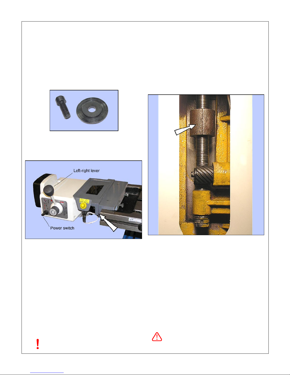
Center the Left-Right lever on the table power feed.
Rotate the speed control knob fully counter-clock-
wise, then clockwise about 45 degrees.
Switch on the table motor. Test the power traverse
function by selecting Left traverse, followed by stop
(center), then Right.
Check that the limit switch assembly stops motion
correctly when actuated by the left and right stop
blocks, Figure 3-4.
Crank handle removed? Headstock locking levers
loose? Run the headstock up the column, Z-axis
motor switch (bottom left) set to Up. Check that the
motor stops as the upper limit switch is actuated,
Figure 2-11.
Check for no obstructions, then run the headstock
down to the lower limit.
Expect to hear a click from the control box when
Up is selected. This is one of the two Z-axis motor
1.
2.
3.
4.
5.
6.
1.
2.
3.
4.
5.
6.
7.
8.
9.
10.
contactors energizing. A similar click from the other
contactor should be heard when Down is selected.
Figure 2-11 Z-axis (elevation) limit switches
These are actuated by the block attached to the headstock
TEST RUN PROCEDURE
Do not leave the machine unattended during this
procedure
Gear levers set to L and 1 (90 rpm)? Gears fully
engaged?
Test the spindle motor by setting the motor switch,
upper right on control box panel, to F (forward) and
R (reverse) in turn.
Run the spindle at 90 rpm for a few minutes, then
stop.
Select each of the available speeds in turn (L-2, L-3,
H-1, etc.). Check gear engagement each time, then
run for a few minutes.
Optional
After a few hours of run time you may wish to drain the
oil to flush out any residue from the manufacturing pro-
cess. This may result in smoother, quieter running, to-
gether with longer service life.
Refill the gearbox with the recommended oil, see
Section 4
The machine should now be ready for normal opera-
tions.
1.
2.
3.
4.
10
PM-940M 10-2016 v1.indd
Everyday precautions
• This machine is intended for use by experienced users familiar with metal-
working hazards.
• Untrained or unsupervised operators risk serious injury.
• Wear ANSI-approved full-face or eye protection at all times when using the
machine (everyday eyeglasses are not reliable protection against flying par-
ticles).
• Wear proper apparel and non-slip footwear – be sure to prevent hair, clothing
or jewelry from becoming entangled in moving parts. Gloves – including tight-
fitting disposables – can be hazardous!
• Be sure the work area is properly lit.
• Never leave chuck keys, wrenches or other loose tools on the machine.
• Be sure the workpiece, toolholder(s) and machine ways are secure before
commencing operations.
• Use moderation: light cuts, low spindle speeds and slow table motion give
better, safer results than “hogging”.
• Don’t try to stop a moving spindle by hand – allow it to stop on its own.
• Disconnect 220 Vac power from the mill before maintenance operations such
as oiling or adjustments.
• Maintain the machine with care – check lubrication and adjustments daily
before use.
• Clean the machine routinely – remove chips by brush or vacuum, not com-
pressed air (which can force debris into the ways).
No list of precautions can cover everything.
You cannot be too careful!