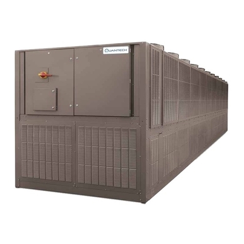
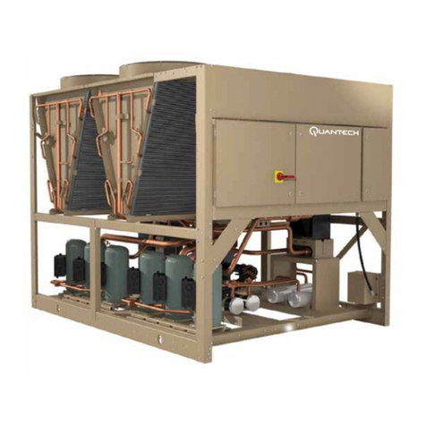
Quantech QTH1 0035 User manual

QTH1 0035, 0075, 0105, and 0140
Air-Cooled Inverter Scroll Chiller and Heat Pump
35 Ton to 140 Ton
Air-Cooled Scroll Liquid Chillers
Quick Start Guide New Release Form QTH1-QSG1 (1223)
Issue Date:
December 20, 2023
R-454B

This equipment is a relatively complicated apparatus.
During rigging, installation, operation, maintenance,
or service, individuals may be exposed to certain com-
ponents or conditions including, but not limited to:
heavy objects, refrigerants, materials under pressure,
rotating components, and both high and low voltage.
Each of these items has the potential, if misused or
handled improperly, to cause bodily injury or death. It
is the obligation and responsibility of rigging, instal-
lation, and operating/service personnel to identify and
recognize these inherent hazards, protect themselves,
and proceed safely in completing their tasks. Failure
to comply with any of these requirements could result
in serious damage to the equipment and the property in
Important!
Read before proceeding!
General safety guidelines
which it is situated, as well as severe personal injury or
death to themselves and people at the site.
This document is intended for use by owner-authorized
rigging, installation, and operating/service personnel.
It is expected that these individuals possess indepen-
dent training that will enable them to perform their
assigned tasks properly and safely. It is essential that,
prior to performing any task on this equipment, this
individual shall have read and understood the on-prod-
uct labels, this document and any referenced materials.
This individual shall also be familiar with and comply
with all applicable industry and governmental stan-
dards and regulations pertaining to the task in question.
Safety symbols
The following symbols are used in this document to alert the reader to specific situations:
Indicates a possible hazardous situation
which will result in death or serious in-
jury if proper care is not taken.
Indicates a potentially hazardous situa-
tion which will result in possible injuries
or damage to equipment if proper care is
not taken.
Identifies a hazard which could lead
to damage to the machine, damage to
other equipment and/or environmental
pollution if proper care is not taken or
instructions and are not followed.
Highlights additional information useful
to the technician in completing the work
being performed properly.
External wiring, unless specied as an optional connection in the manufacturer’s product line, is not
to be connected inside the control cabinet. Devices such as relays, switches, transducers and controls
and any external wiring must not be installed inside the micro panel. All wiring must be in accor-
dance with Johnson Controls’ published specications and must be performed only by a qualied
electrician. Johnson Controls will NOT be responsible for damage/problems resulting from improper
connections to the controls or application of improper control signals. Failure to follow this warning
will void the manufacturer’s warranty and cause serious damage to property or personal injury.
Quantech
2
Form QTH1-QSG1
Issue date: 12/20/2023

Changeability of this document
In complying with Johnson Controls’ policy for contin-
uous product improvement, the information contained
in this document is subject to change without notice.
Johnson Controls makes no commitment to update
or provide current information automatically to the
manual or product owner. Updated manuals, if appli-
cable, can be obtained by contacting the nearest John-
son Controls Service office or accessing the Johnson
Controls Knowledge Exchange website at https://docs.
johnsoncontrols.com/chillers/
It is the responsibility of rigging, lifting, and operating/
service personnel to verify the applicability of these
documents to the equipment. If there is any question
regarding the applicability of these documents, rig-
ging, lifting, and operating/service personnel should
verify whether the equipment has been modified and
if current literature is available from the owner of the
equipment prior to performing any work on the chiller.
Manual description Form number
Installation, Commissioning, Operations, and Maintenance QTH1-ICOM1
Chiller A2L Refrigerant Application Data 160.00-AD10
ASSOCIATED LITERATURE
External wiring, unless specied as an optional connection in the manufacturer’s product line, is not
to be connected inside the control cabinet. Devices such as relays, switches, transducers and controls
and any external wiring must not be installed inside the micro panel. All wiring must be in accor-
dance with Johnson Controls’ published specications and must be performed only by a qualied
electrician. Johnson Controls will NOT be responsible for damage/problems resulting from improper
connections to the controls or application of improper control signals. Failure to follow this warning
will void the manufacturer’s warranty and cause serious damage to property or personal injury.
Working with chiller vessels which are designed to contain contents under pressure must only be
conducted by fully qualied technicians who have been certied in accordance with EPA Section 608
of the Clean Air Act requirements for the US or equivalently the Federal Halocarbon Regulations
and the Refrigerant Code of Practice for Canada. This equipment is only intended for installation
in locations that are not accessible to the general public. Further, this equipment is not intended for
use by persons (including children) with reduced physical, sensory or mental capabilities, or lack
of experience and knowledge. Refrigerant R-454B is classied as an A2L refrigerant and must be
handled in accordance with all governing regulations. Failure to meet this requirement can result
in damage to equipment, release of refrigerant into the environment, contamination of the operating
space for the equipment and pose a risk of personal injury or death. It is the responsibility of any
service technician or operator to adhere to these requirements. See 160.00-AD10 for greater details
regarding the application and use of A2L refrigerants.
Quantech 3
Form QTH1-QSG1
Issue date: 12/20/2023

Table of Contents
Introduction..............................................................................................................................................................5
Handling and installation........................................................................................................................................5
Single unit ................................................................................................................................................................5
Electrical checks: power off..............................................................................................................................5
Customer wiring ...............................................................................................................................................6
Control configuration: power on .....................................................................................................................10
Mechanical checks .........................................................................................................................................10
Modular units installation.....................................................................................................................................15
Micro DIP switch configuration, SW301 from 1 to 5 .......................................................................................15
Quantity of combined modules.......................................................................................................................15
Micro DIP switches configuration, SW301 from 6 to 8 and SW302:...............................................................15
BMS control ...........................................................................................................................................................16
Cabling requirements .....................................................................................................................................18
Modbus and BACnet ......................................................................................................................................19
Quantech
4
Form QTH1-QSG1
Issue date: 12/20/2023

Introduction
Use this guide to quickly get started with the commu-
nications setup for the QTH1. For more information,
refer to Form QTH1-ICOM1.
Handling and installation
For correct chiller and heat pump transportation, in-
stallation, and hydraulic connections refer to Form
QTH1-ICOM1.
Single unit
Electrical checks: power off
The QTH1 requires an electrical connection with a
power of 460 VAC, 60 Hz. Refer to Technical data in
Form QTH1-ICOM1 for more information.
Figure 1: Power supply location
Figure 2: Power supply wiring
Callout Description Callout Description
A Single module power supply C Pump fuse
B External wiring D SPC power supply
Quantech 5
Form QTH1-QSG1
Issue date: 12/20/2023

Customer wiring
Flow switch SFM1: 80K-92 (XT2)
• Models 0035PJP to 140PJP: Default factory
installation and wiring
• Models 0035PJS to 140PJS: Loose ship and eld
wiring
Figure 3: Cold water flow switch SFM1, single module
Flow switch SFM2: 80L-93 (XT2)
Figure 4: Hot water flow switch SFM2, single module
External interlock
Install an electrical link on terminals 80H-88 (XT2), if
required.
Figure 5: External interlock
Models 0035 PJS to 140 PJS: Loose ship and field wiring.
SFM2 is only for the hot water loop on the PJS four-pipe
models. PJP two-pipe models don't have SFM2
Quantech
6
Form QTH1-QSG1
Issue date: 12/20/2023

Configuring the unit for remote start and stop
1. Wire dry contacts to XT2 terminals 80G-87. See
the wiring diagram in Figure 5 on page 6.
2. From the System Setpoints menu on the hu-
man-machine interface (HMI), select Remote for
ON/OFF Control Select if the customer requires
digital input (DI) remote control for the start or
stop switch.
Figure 6: Location of the HMI on the units
Configuring the unit for remote operation mode
selection
1. Wire dry contacts to XT2 terminals 80F-86 for
cooling or heating mode, and 80D-84 for simul-
taneous cooling and heating mode. See the wiring
diagram in Figure 5 on page 6.
2. From the System Setpoints menu on the HMI,
select Remote for Mode Control Select if the
customer requires DI remote control for operation
mode switch.
Quantech 7
Form QTH1-QSG1
Issue date: 12/20/2023
Interlocking external water pump
The dry contact of cold-water pump control is on ter-
minals TB1:1-2 (DO1-E) of the relay board (ARB).
The dry contact of hot-water pump control is on ter-
minals TB3:1-2 (DO3-E) of the ARB. Four pipe units
need to connect both cold water pumps and hot water
pumps, while the two pipe units need to connect pumps
for one water loop with DO1-E. Refer to the installa-
tion section of ICOM for model specifications.
Figure 7: Interlocking external water pump
Inlet and outlet pipe heater of cold water BPHE:
EPH11 and EPH12
The active contact for the inlet and outlet pipe heat-
er for cold-water BPHE is on terminals 76B-2B. The
wiring for the heater in control panel is finished in the
factory, and is only for model 0035PJP.
Inlet pipe heater of cold-water hydro kit: EPH13
The active contact for cold-water pump control is on
terminals 76C-2C in the control panel. The wiring be-
tween the hydro kit and control panel needs to be fin-
ished in the field, except for hydro kits combined with
units, such as 0035PJP.
Outlet pipe heater of cold-water hydro kit: EPH14
The active contact for cold-water pump control is on
terminals 76D-2D in the control panel. The wiring be-
tween the hydro kit and control panel is finished in the
factory, and the heater (EPH14) is only available for
model 0035PJP, which is combined with the hydro kit.
This can also be reserved for customers who need to
install a heater on the outlet pipe of the cold-water hy-
dro kit for other modules.
Inlet pipe heater of hot-water hydro kit: EPH23
The active contact for hot-water pump control is on
terminals 77C-2G in the control panel. The wiring be-
tween the hydro kit and control panel needs to be fin-
ished in field.
Outlet pipe heater of hot-water hydro kit: EPH24
The active contact for hot-water pump control is on
terminals 77D-2H in control panel. This is reserved for
customers who need to install a heater on the output
pipe of hot-water hydro kit.
Quantech
8
Form QTH1-QSG1
Issue date: 12/20/2023
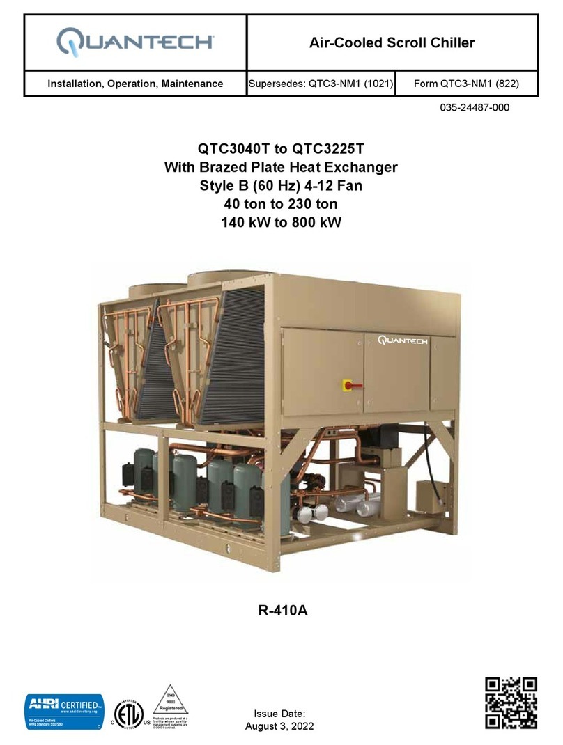
Table 1: Electrical cable connections
Model Max.
FLA
(A)
Voltage
(V)
MCA
(A)
Max. dual
elem.
fuse/CB
(Max OP,
A)
Screw/nut Recommended conductor size
Phase,
recommended
torque
PE,
recommended
torque
Phase
(AWG)
Number of
conductors
per phase
PE
(AWG)
Number
of PE
conductors
0035PJS 84
460
92 110 M8, 15N.M M8, 18N.M 2
1
6
1
0070PJS 151 159 175
M10, 38N.M M10, 25N.M
2/0 2
0105PJS 262 270 300 1/0
2
4
2
0140PJS 328 336 350 3/0 1/0
0035PJP 75 83 110 M8, 15N.M M8, 18N.M 2
1
6
1
0070PJP 142 149 175
M10, 38N.M M10, 25N.M
2/0 2
0105PJP 230 238 250 1/0
242
0140PJP 296 304 300 3/0 1/0
Notes:
• The hydraulic kit is considered in the data of this table.
• The maximum distance is calculated taking the cable diameters shown in this table. For longer lengths, and for cables laying with other
cables, the minimum cable diameter must be recalculated to a higher value to allow for any electromagnetic or harmonic eects.
Refer to the dimensions of any power cable connectors to ensure the correct tting to the specied
power cables and circuit breaker. Due to the high risk of electrical shock and in compliance with
electrical regulations, cable and power terminals must be protected. Any accessories to adapt allow-
able cable connections can be sourced at he relevant manufacturer's site. The number of options
are too numerous to list here.
Hydro kits, SPC breakers, and 575 V panel breaker are from Siemens, 460 V control panel breakers
are from Schneider Electric.
Quantech 9
Form QTH1-QSG1
Issue date: 12/20/2023
Mechanical checks
Control configuration: power on
Apply power to the chiller 8 h before start-up.
Changing the access level
There are three access levels in the HMI control:
• V: Viewer
• O: Operator
• S: Service
To change the access level, complete the following
steps:
1. Press the letter in the upper-right corner of the
HMI screen.
Ensure the suction and discharge service valves of each
refrigeration circuit are open.
2. Press Change Access Level.
3. Enter the password and press the enter key.
• Operator password: 9017
The access level indication in the upper-right cor-
ner changes accordingly.
Configuring the language
1. In access level O, press HMI in the menu.
2. Select Language Setpoint, select the appropriate
language, and press enter.
Figure 8: Location of service isolation valve in suction and discharge side
PS
OS
OS
PS
BV2
Coil
FanEEV2
F1
YDSV
Service Ball Valve
Service Access Valve
Solenoid Valve
Electronic Expansion Valve
4 way Reversing Valve
Check Valve
Pressure Relief Valve
Pressure Switch
Filter
Oil Seperator
Supply
Return
BPHE 2
Receiver
YOSV
YESV
Compressor
Accumulator
F2
BV1
RV1/2
RV3/4
FWV
Supply
Return
BPHE 1
YASV
YCSV
CV1
CV2
Charging
BPHE3
CV3
CV4EEV1
Quantech
10
Form QTH1-QSG1
Issue date: 12/20/2023
Setting the date and time
1. In access level O, press HMI in the menu and se-
lect Date Time Setpoint.
2. Set the date and time and press Conrm.
Setting a schedule
1. In access level O or S, press Schedule in the
menu.
2. Press the +icon to add a new item.
3. Congure the settings using the icons on the right.
• Press the - icon to delete an item.
See the following figure for an example of the screen.
Figure 9: Setting a schedule
Setting the water temperature control using
entering water temperature (EWT) or leaving water
temperature (LWT)
1. In access level O, press System Setpoints in the
menu.
2. Select Cooling/Heating Control Select.
Setting a setpoint
1. In access level O, press System Setpoints in the
menu.
2. Congure the target liquid temperature setpoints
in Cool/Heat EWT Setpoint or Cool/Heat LWT
Setpoint.
3. Set according to cooling/heating control selection.
• For setpoint temperature less than 40°F
(4.4°C), see Low temperature leaving alarm
on page 12.
Setpoint temperature less than 41ºF (5ºC):
To work with setpoints between 40ºF (4.4ºC) and 14ºF
(-10ºC), use glycol liquid with the correct concentra-
tion in the water system and configure the micro DIP
switches SW302-3 and SW302-4 on the control board
in the control panel to glycol mode. See Figure 11 on
page 12 for more details. If you need year-round
cooling in low ambient temperature less than 41℉
(5℃), Quantech suggests using glycol liquid.
Figure 10: Setpoint temperatures less than 41ºF (5ºC)
Condition SW302-3 SW302-4 Note
Glycol O O –
Standard O On Default
48ºC
COOLING MODE
-10ºC 4.4ºC 20ºC
Leaving water cooled temperature
Ambient temperature
-20ºC
Quantech 11
Form QTH1-QSG1
Issue date: 12/20/2023
Low temperature leaving alarm
1. In access level O, press System Setpoints and se-
lect Low LWT Alarm.
2. Set the low LWT alarm temperature to between
5.4℉ and 9℉ (3℃ and 5℃) above the liquid
freeze temperature point. For example, if the gly-
col liquid freeze point is 14℉ (-10℃), you can set
the alarm point to 23℉ (-5℃).
Setting the operating mode
1. In access level O, press System Setpoints in the
menu and select Operating Mode.
2. Set the mode to Cooling/Heating/Cooling+Heat-
ing/Pump Only.
Chiller Start/Shutdown
1. In access level O, press System Setpoints in the
menu and select Chiller Start/Shutdown.
2. Set the stop/run of the chiller.
Faults
In access level O, press Fault in the menu to view the
active faults, reset faults, and to delete the fault history.
• To reset a fault if the alarm condition has been
corrected, press Reset Fault at the bottom of the
screen. The access level must be at O or S, de-
pending on the fault level to be reset.
• To clear the history of inactive faults, press Clear
History at the bottom-right of the screen. You can
only clear the fault history with S level access.
Active faults are colored blue, while recognized faults
in the fault history are colored black. Press on a fault
item to access detailed information about it.
Figure 11: Fault screen
Additional checks for models 0070 to 0140
Models 0070, 0105, and 0140 are modular arrays,
which require additional checks as shown the follow-
ing sections.
Figure 12: 0140 modular array example
Configuring 0035, 0070, 0105, and 0140PJP/S
models
Check and configure the micro DIP switches SW301
of each control board (microboard) according to the
following tables for each module in a modular array
unit.
Table 2: DIP switch setting for each module address
Module SW301-1 SW301-2 SW301-3 SW301-4 SW301-5
1 On O O O O
2O On O O O
3 On On O O O
4O O On O O
5 On O On O O
6O On On O O
7 On On On O O
8O O O On O
9 On O O On O
10 O On O On O
11 On On O On O
12 O O On On O
13 On O On On O
14 O On On On O
15 On On On On O
16 O O O O On
17 On O O O On
18 O On O O On
19 On On O O On
20 O O On O On
21 On O On O On
Quantech
12
Form QTH1-QSG1
Issue date: 12/20/2023
Module SW301-1 SW301-2 SW301-3 SW301-4 SW301-5
22 O On On O On
23 On On On O On
24 O O O On On
25 On O O On On
26 O On O On On
27 On On O On On
28 O O On On On
29 On O On On On
30 O On On On On
31 On On On On On
32 O O O O O
Table 2: DIP switch setting for each module address,
continued
The micro DIP switches SW301-6, SW301-7, and
SW301-8 on each control board relate to the unit mod-
ule type, either two pipe PJP or four pipe PJS. These
three DIP switch are set in the factory according to the
unit model number.
Table 3: DIP switch model setting
Model SW301-6 SW301-7 SW301-8
0035PJS On On O
0035PJP On On On
Figure 13: 0035PJP/S configuration
You can nd the control board DIP switch deni-
tion details in the electrical diagrams on the inside
of each control panel.
Quantech 13
Form QTH1-QSG1
Issue date: 12/20/2023
Setting the qauntity of combined modules
1. In access level O, press System Setpoints in the
menu and select Unit Quantity.
2. As an example, for a modular array that includes
two single modules or a combination of two mod-
ules, set the quantity of modules to 2. Each mod-
ule has a control panel.
Sequence module selection
1. In access level O, press Unit in the menu and se-
lect Unit Selection.
2. To view the data of each separate module on com-
bined modules, choose the module number you
want to check. See the following gure for more
information.
Figure 14: Sequence module selection
Quantech
14
Form QTH1-QSG1
Issue date: 12/20/2023

Modular units installation
For modular systems, see Single unit on page 5 for
setup information for each single module before fol-
lowing instructions in this section.
Micro DIP switch configuration, SW301
from 1 to 5
Set one module control board as address 1, the leader,
and set the other module's DIP switches in ascending
order. For each modular combination application, con-
figure one leader address.
Modular array 0070, 0105, and 0140 have
multicontrol boards. The communication
address needs to be set with SW301 dip
switch. The module with the HMI needs
to be set as the leader.
Quantity of combined modules
Configure the number of total modules in a modular
system. Each single module has a control panel.
Micro DIP switches configuration, SW301
from 6 to 8 and SW302:
Flow switch
Each individual module has a standard flow
switch. The flow switch for PJP two pipe models is
factory-installed. The flow switch for PJS four pipe
models needs to be wired in the field.
Remote start or stop and remote mode selection
If you require this functionality, only connect them in
the leader unit and activate this function in the HMI
of the leader unit. See Configuring the unit for remote
start and stop on page 7 and Configuring the unit
for remote operation mode selection on page 7 for
more information.
Sensor in the manifold/common water pipe
If using a return temperature control, it is not necessary
to have an additional system return water temperature
sensor. Otherwise, if using a leaving temperature con-
trol, connect an additional system leaving temperature
sensor to the common pipe and connect the wiring to
the leader unit control panel. The system leaving tem-
perature sensor is shipped loose with the unit and must
be configured on site.
• BLST1: Leaving temperature sensor for cold wa-
ter loop, available for both two pipe and four pipe
models.
• BLST2: Leaving temperature sensor for hot water
loop, only available for PJS four pipe models.
Figure 15: Sensor in the manifold/common water pipe
Callout Description
A Connection of the impulse sensor in the
common pipe
Shut-off valve for each chiller
For modular applications with multi-modules combi-
nations, in order to avoid water passing through the
modules that are stopped, the automatic shut-off water
valves (on/off) can be installed for individual modules.
The contact for the cold water valve control is on TB2
DO2-E of the ARB, and the contact for the hot water
valve control is on TB4 DO4-E. Four-pipe units need
to connect both cold water and hot water valves for two
water loops, while the two pipe units only need to con-
nect the cold water valve for one water loop. For mod-
ules with an automatic control valve installed, set the
DIP Switch SW302-6 as non-shared pump/with water
system valve (YWSV) according to the Figure 16 on
page 16. Keep SW302-6 of the leader modules set as
shared pump/no YWSV.
Quantech 15
Form QTH1-QSG1
Issue date: 12/20/2023

Figure 16: Shut-off valve and DIP switch setting
DIP OFF ON Default
SW302-6 Non-shared
pump with
YWSV
Shared
pump, no
YWSV
ON
Leader-follower interconnections
The interconnection between the leader and follower
chillers is carried out through the CON 204 according
to the scheme described in Figure 19 on page 18.
In a leader-follower chiller configuration, view the pa-
rameters settings or operation data check on the HMI,
which is installed on leader module.
View the readings of the follower chillers through the
leader HMI. By selecting the number of the module in
the Unit Selection menu, you can read the parameters
of the module selected.
BMS control
The QTH1 building management controls use the RS-
485 standard, including BACnet MS/TP, Modbus RTU,
or N2 connectivity for communication with virtually
any building management system (BMS), including
Verasys™ controls systems.
This advanced, embedded control capability also al-
lows multiple heat pumps to be connected and mon-
itored through a single controller. Each unit features a
touchscreen display that has an easy-to-use, web-style
interface and intuitive navigation for easy access to op-
erational data. Information can be displayed in multi-
ple languages and setup is very easy.
To simplify installation and setup, the SC-EQ commu-
nication board automatically determines the building
automated system (BAS) protocol, baud rate, and the
model of the connected chiller or rooftop unit. The
only user setting is the MAC address for the SC-EQ
on the BAS network. The network hardware address
for the SC-EQ comm card is set on a single 8-way DIP
switch. Switch 8 is not used. The switches are binary
weighted allowing the setting of addresses from 1 to
127. For more information about SC-EQ communica-
tion card instructions, refer to SC-EQ Communication
Card, Form 450.50-N1.
The SC-EQ board is a standard configuration on QTH1
units. In a modular installation, the SC-EQ card on the
leader module must be active. For SC-EQ card loca-
tion, see Figure 18 and SC-EQ card configuration see
Figure 19 on page 18.
Quantech
16
Form QTH1-QSG1
Issue date: 12/20/2023

Figure 17: SC-EQ card location, MAC address and BAS connection port
Callout Description Callout Description
A MAC address DIP switch B BAS port J3
Figure 18: SC-EQ card
Callout Description Callout Description
A USB port E EQ 485 port
B Flash IC F Connected services RJ
C Debug G BAS 485 port
D MAC address switch H Power supply input 100 VAC to 240 VAC
Quantech 17
Form QTH1-QSG1
Issue date: 12/20/2023

Cabling requirements
The BAS port on the SC-EQ board in the electrical
cabinet of the leader module unit is the communication
interface between the unit and the BMS. The customer
needs a RS-232/RS-485 converter between the SC-EQ
BAS port and the customer BAS. The communication
line has polarity: A is connected to converter A (or +),
B is connected to converter B (or -). To avoid malfunc-
tion, ensure it is connected correctly.
Table 4 on page 18 outlines the cable length and type
for interconnections.
Figure 19: Leader-follower modules communication wiring connection
Table 4: Interconnection cable length and type
Total length
L = L2 + L3 + ... + Ln (n ≤ 32, m)
L < 100 m 100 m < L < 500 m L > 500 m
Cable type Shielded twisted pair cable
2 x 0.75 mm2
Shielded twisted pair cable
2 x 1.0 mm2
Contact Quantech
Figure 20: Converter between SC-EQ BAS port and customer BAS
Quantech
18
Form QTH1-QSG1
Issue date: 12/20/2023

Figure 21: SC-EQ wiring diagram
If BAS control connection is required, unit ON/OFF
Control or Mode Selection Control in HMI. Figure 22
is setup interface example of ON/OFF Control Select.
Comm (BAS) and HMI selection
Modbus and BACnet
For the most recent points lists and protocol instruc-
tion for the two-pipe and four-pipe units, refer to the
Points List Two-Pipe Equipment and Points List Four-
Pipe Equipment on the Chillers Knowledge Exchange:
https://docs.johnsoncontrols.com/chillers/
Quantech 19
Form QTH1-QSG1
Issue date: 12/20/2023

Quantech Incorporated www.Quantech-HVAC.com Subject to change without notice. Printed in USA
Copyright © 2023 All Rights Reserved
Form QTH1-QSG1 (1223)
Issue Date: December 20, 2023
Supersedes: New Release
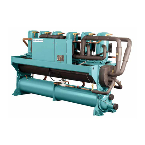
This manual suits for next models
3
Table of contents
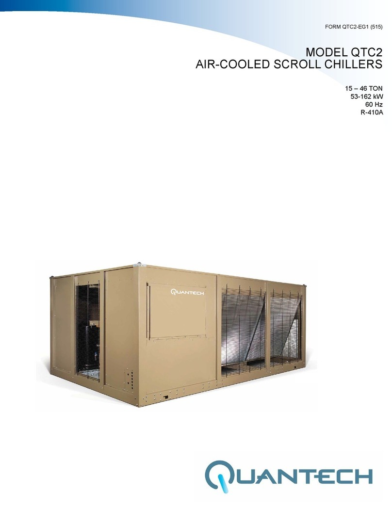
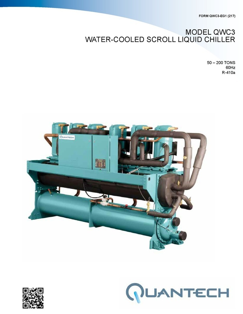
Other Quantech Chiller manuals
Popular Chiller manuals by other brands

Blichmann Engineering
Blichmann Engineering Glycol Chiller Assembly operation maintenance

Alto-Shaam
Alto-Shaam Quickchiller QC-100 Installation and maintenance manual

Ecoplus
Ecoplus 1/10 HP instruction manual

Fryka
Fryka Hei-CHILL 400 Pro operating instructions

Midea
Midea MGCT-F30W/PN1 manual

S&A
S&A CW-6300 user manual

McQuay
McQuay MAC040A Installation and maintenance manual

Viessmann
Viessmann Vitoclima 200-C Service instructions for contractors

Skope
Skope ActiveCore BME-N Series Service manual

York
York Millennium YCAS Series Installation operation & maintenance

York
York YK Installation

Solid State Cooling Systems
Solid State Cooling Systems ThermoCube product manual