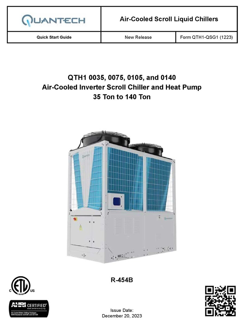
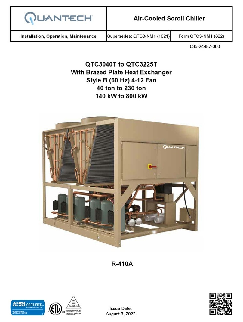
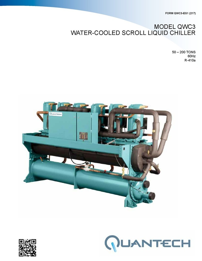
Quantech QWC3050T-200T Owner's manual

QWC3050T-200T
WATER-COOLED LIQUID CHILLERS
STYLE A (60 HZ)
50 - 200 TONS
175KW THROUGH 700KW
INSTALLATION, OPERATION, MAINTENANCE
WATER-COOLED LIQUID CHILLERS
HERMETIC SCROLL
Supersedes: QWC3-NM1 (1118) Form: QWC3-NM1 (1120)
PART # 035-26707-000
R410A
Issue Date:
November 20, 2020
Products are produced at a
f a c i l i t y w h o s e q u a l i t y -
management systems are
ISO9001 certified.

FORM QWC3-NM1
ISSUE DATE: 11/20/2020
QUANTECH
2
This equipment is a relatively complicated apparatus.
During installation, operation maintenance or service,
individuals may be exposed to certain components or
conditions including, but not limited to: refrigerants,
materials under pressure, rotating components, and
both high and low voltage. Each of these items has the
potential, if misused or handled improperly, to cause
bodily injury or death. It is the obligation and respon-
sibility of operating/service personnel to identify and
recognize these inherent hazards, protect themselves,
and proceed safely in completing their tasks. Failure
to comply with any of these requirements could result
in serious damage to the equipment and the property in
IMPORTANT!
READ BEFORE PROCEEDING!
GENERAL SAFETY GUIDELINES
which it is situated, as well as severe personal injury or
death to themselves and people at the site.
This document is intended for use by owner-authorized
operating/service personnel. It is expected that these
individuals possess independent training that will en-
able them to perform their assigned tasks properly and
safely. It is essential that, prior to performing any task
on this equipment, this individual shall have read and
understood this document and any referenced mate-
rials. This individual shall also be familiar with and
comply with all applicable governmental standards and
regulations pertaining to the task in question.
SAFETY SYMBOLS
The following symbols are used in this document to alert the reader to specific situations:
Indicates a possible hazardous situation
which will result in death or serious injury
if proper care is not taken.
Indicates a potentially hazardous situa-
tion which will result in possible injuries
or damage to equipment if proper care is
not taken.
Identies a hazard which could lead to
damage to the machine, damage to other
equipment and/or environmental pollu-
tion if proper care is not taken or instruc-
tions and are not followed.
Highlights additional information useful
to the technician in completing the work
being performed properly.
External wiring, unless specied as an optional connection in the manufacturer’s product line, is
not to be connected inside the control cabinet. Devices such as relays, switches, transducers and
controls and any external wiring must not be installed inside the micro panel. All wiring must be
in accordance with Quantech’s published specications and must be performed only by a qualied
electrician. Quantech will NOT be responsible for damage/problems resulting from improper con-
nections to the controls or application of improper control signals. Failure to follow this warning
will void the manufacturer’s warranty and cause serious damage to property or personal injury.

FORM QWC3-NM1
ISSUE DATE:11/20/2020
QUANTECH 3
MANUAL DESCRIPTION FORM NUMBER
Unit Replacement Parts QWC3--RP1
Unit Start-Up Checklist QWC3-CL1
All Products - Replacement Parts Electrical Connectors 50.20-RP1
All Products - Replacement Parts Fittings 50.20-RP2
ASSOCIATED LITERATURE
This manual contains installation, op-
eration and maintenance instructions for
both single and dual refrigerant circuit
models. If your unit is a single circuit
model (QTC2015T-030T), disregard refer-
ences to “System 2” which may appear in
this manual. Any references to Sys 2 are
applicable to QTC2015T-045T models.
SINGLE CIRCUIT AND DUAL CIRCUIT MODELS
CHANGEABILITY OF THIS DOCUMENT
In complying with Johnson Controls’ policy for con-
tinuous product improvement, the information con-
tained in this document is subject to change without
notice. Johnson Controls makes no commitment to
update or provide current information automatically
to the manual or product owner. Updated manuals, if
applicable, can be obtained by contacting the nearest
Johnson Controls Service office or accessing the John-
son Controls Knowledge Exchange website at https://
docs.johnsoncontrols.com/chillers/.
It is the responsibility of rigging, lifting, and operating/
service personnel to verify the applicability of these
documents to the equipment. If there is any question
regarding the applicability of these documents, rig-
ging, lifting, and operating/service personnel should
verify whether the equipment has been modified and
if current literature is available from the owner of the
equipment prior to performing any work on the chiller.
REVISION NOTES
Revisions made to this document are indicated in the following table. These revisions are to technical information,
and any other changes in spelling, grammar, or formatting are not included.
AFFECTED PAGES DESCRIPTION
46,47 Physical Data table units updated
48-55 Electrical Data table units updated
171-181 Data maps updated

FORM QWC3-NM1
ISSUE DATE: 11/20/2020
QUANTECH
4
THIS PAGE INTENTIONALLY LEFT BLANK.

FORM QWC3-NM1
ISSUE DATE:11/20/2020
QUANTECH 5
TABLE OF CONTENTS
SECTION 1 – GENERAL CHILLER INFORMATION AND SAFETY ................................................................ 11
Introduction..................................................................................................................................................... 11
Warranty ......................................................................................................................................................... 11
Safety ............................................................................................................................................................. 11
Misuse Of Equipment .....................................................................................................................................12
SECTION 2 – PRODUCT DESCRIPTION...........................................................................................................13
Introduction..................................................................................................................................................... 13
Compressors ..................................................................................................................................................13
Refrigerant Circuits......................................................................................................................................... 13
Evaporator......................................................................................................................................................14
Condenser......................................................................................................................................................14
Refrigerant Circuit ..........................................................................................................................................14
Microprocessor Control Center ...................................................................................................................... 14
Power Panel ..................................................................................................................................................15
Accessories And Options ...............................................................................................................................16
Control / Power Panel Components ...............................................................................................................18
Unit Components............................................................................................................................................ 20
Product Identification Number (Pin) ...............................................................................................................22
Refrigerant Flow ............................................................................................................................................26
SECTION 3 – TRANSPORTATION, HANDLING AND STORAGE ...................................................................29
Delivery And Storage......................................................................................................................................29
Inspection .......................................................................................................................................................29
Moving The Unit .............................................................................................................................................29
Lifting Weights................................................................................................................................................30
SECTION 4 – INSTALLATION .............................................................................................................................31
Installation Checklist....................................................................................................................................... 31
Location Requirements ..................................................................................................................................31
Unit Isolation (Noise Sensitive Location)........................................................................................................31
Foundation .....................................................................................................................................................31
Installation Of Vibration Isolators ...................................................................................................................32
Pipework Connection .....................................................................................................................................32
Water Treatment.............................................................................................................................................34
Option Flanges ...............................................................................................................................................34
Refrigerant Relief Valve Piping.......................................................................................................................34
Condenser Cooling Liquid Systems ...............................................................................................................35
Pressure Tapping............................................................................................................................................36
Pipework Arrangement ...................................................................................................................................36
Connection Types And Sizes..........................................................................................................................36
Electrical Connection...................................................................................................................................... 37
Field Wiring ....................................................................................................................................................37
Control Panel Wiring ...................................................................................................................................... 37
Power Wiring ..................................................................................................................................................38
Compressor Heaters ......................................................................................................................................39
Relief Valves...................................................................................................................................................39
High Pressure Cutout .....................................................................................................................................39
Control Wiring................................................................................................................................................. 40

FORM QWC3-NM1
ISSUE DATE: 11/20/2020
QUANTECH
6
TABLE OF CONTENTS (CONT’D)
SECTION 5 – TECHNICAL DATA........................................................................................................................41
Operational Limitations................................................................................................................................... 41
Condenser Pressure Drop Charts ..................................................................................................................44
Ethylene And Propolyne Glycol Correction Factors .......................................................................................45
Physical Data - Standard And High Efficiency................................................................................................46
Single Point Electrical Data ............................................................................................................................48
Dual Point Electrical Data............................................................................................................................... 56
Dual Point Electrical Data............................................................................................................................... 58
Single-Point Supply Connection – Terminal Block,
Non-Fused Disconnect Switch Or Circuit Breaker .........................................................................................60
Dual-Point Supply Connection – Terminal Block,
Non-Fused Disconnect Switch Or Circuit Breaker .........................................................................................61
Electrical Data ................................................................................................................................................62
Electrical Notes And Legend ..........................................................................................................................63
Ground Wire Sizing ........................................................................................................................................64
Elementary Wiring Diagram ........................................................................................................................... 66
Connection Wiring Diagram ........................................................................................................................... 74
Elementary Wiring Diagram Details ............................................................................................................... 82
Unit Dimensions - Four Compressor ..............................................................................................................87
Unit Dimensions - Five And Six Compressor .................................................................................................89
SECTION 6 – COMMISSIONING .......................................................................................................................107
Preparation – Power Off...............................................................................................................................107
Preparation – Power On...............................................................................................................................109
Unit Operating Sequence ............................................................................................................................. 113
SECTION 7 – UNIT CONTROLS........................................................................................................................ 115
Introduction................................................................................................................................................... 115
Status Key .................................................................................................................................................... 117
Status Key Messages................................................................................................................................... 122
Display/Print Keys ........................................................................................................................................123
Entry Keys ....................................................................................................................................................131
Setpoints Keys .............................................................................................................................................132
Unit Keys .....................................................................................................................................................139
SECTION 8 – UNIT OPERATION ......................................................................................................................147
Capacity Control...........................................................................................................................................147
Suction Pressure Limit Controls ...................................................................................................................147
Discharge Pressure Limit Controls...............................................................................................................147
Leaving Chilled Liquid Control...................................................................................................................... 147
Leaving Chilled Liquid Control Override To Reduce Cycling........................................................................148
Leaving Chilled Liquid System Lead/Lag And Compressor Sequencing .....................................................148
Return Chilled Liquid Control .......................................................................................................................149
Return Chilled Liquid System Lead/Lag And Compressor Sequencing .......................................................150
Anti-Recycle Timer ....................................................................................................................................... 151

FORM QWC3-NM1
ISSUE DATE:11/20/2020
QUANTECH 7
TABLE OF CONTENTS (CONT’D)
Anti-Coincidence Timer ................................................................................................................................ 151
Evaporator Pump Control And Hydro Kit Pump Control...............................................................................151
Evaporator Heater Control ...........................................................................................................................151
Pumpdown Control.......................................................................................................................................151
Load Limiting ................................................................................................................................................151
Compressor Run Status ...............................................................................................................................152
Alarm Status.................................................................................................................................................152
Ems-Pwm Remote Temperature Reset........................................................................................................152
Bas/Ems Temperature Reset Using A Voltage Or Current Signal ................................................................ 153
SECTION 9 – SERVICE AND TROUBLESHOOTING ..................................................................................... 155
Clearing History Buffers................................................................................................................................ 155
Service Mode ...............................................................................................................................................155
Service Mode – Outputs...............................................................................................................................155
Service Mode – Chiller Configuration...........................................................................................................156
Service Mode – Analog And Digital
Inputs............................................................................................................................................................ 156
Control Inputs/Outputs .................................................................................................................................157
Microboard Layout........................................................................................................................................ 158
Checking Inputs And Outputs.......................................................................................................................159
Optional Printer Installation ..........................................................................................................................163
Acceptable Printers ......................................................................................................................................163
Printer Connections......................................................................................................................................163
Printer Setup ................................................................................................................................................163
Printing A Report ..........................................................................................................................................164
Troubleshooting............................................................................................................................................165
SECTION 10 – MAINTENANCE.........................................................................................................................169
Important ......................................................................................................................................................169
Compressors ................................................................................................................................................169
Operating Parameters ..................................................................................................................................169
On-Board Battery Back-Up........................................................................................................................... 169
Overall Unit Inspection .................................................................................................................................169
BACnet And Modbus Data Communications................................................................................................170
Temperature Conversion Chart ....................................................................................................................184
R410-A
Pressure Temperature Chart ........................................................................................................................185
Temperature .................................................................................................................................................186

FORM QWC3-NM1
ISSUE DATE: 11/20/2020
QUANTECH
8
LIST OF FIGURES
FIGURE 1 - QWC3 Water Cooled Liquid Chiller ....................................................................................................13
FIGURE 2 - Control / Panel Compowwnents..........................................................................................................18
FIGURE 3 - Control Power Panel Components......................................................................................................19
FIGURE 4 - Unit Components ................................................................................................................................20
FIGURE 5 - Control / Power Panel Components Dual System Units .....................................................................21
FIGURE 6 - Refrigerant Flow Diagram ...................................................................................................................26
FIGURE 7 - Process and Instrumentation Diagram................................................................................................27
FIGURE 8 - Chiller Rigging And Lifting Weights.....................................................................................................30
FIGURE 9 - ANSI/AWWA C-606 - Adapter Flanges........................................................................................................ 34
FIGURE 10 - Direct Pressure Control Diagram......................................................................................................35
FIGURE 11 - Inlet Temperature Control Diagram ...................................................................................................35
FIGURE 12 - Chilled Liquid System .......................................................................................................................36
FIGURE 13 - Condenser Cooling Liquid System....................................................................................................36
FIGURE 14 - Pipework Arrangements Legend.......................................................................................................36
FIGURE 15 - Cooler Connections ..........................................................................................................................36
FIGURE 16 - Control Wiring ...................................................................................................................................40
FIGURE 17 - Evaporator Water Pressure Drop Curves ........................................................................................43
FIGURE 18 - Condenser Water Pressure Drop Curves .........................................................................................44
FIGURE 19 - Glycol Solution Strengths..................................................................................................................45
FIGURE 20 - Single Point Power Supply Connection – Standard Unit ..................................................................60
FIGURE 21 - Dual Point Power Supply Connection – Standard Unit.....................................................................61
FIGURE 22 - Control Circuit, 4 Compressor...........................................................................................................66
FIGURE 23 - Control Circuit, 5 And 6 Compressor ................................................................................................68
FIGURE 24 - Power Circuit, 4 Compressor With Non Fused Disconnect Switch Or Circuit Breaker.....................70
FIGURE 25 - Power Circuit, 4 Compressor With Circuit Breaker...........................................................................71
FIGURE 26 - Power Circuit, 5 And 6 Compressor..................................................................................................72
FIGURE 27 - Power Circuit, 6 Compressor............................................................................................................73
FIGURE 28 - Connection Wiring Diagram, 4 Compressor .....................................................................................74
FIGURE 29 - Connection Wiring Diagram, 4 Compressor .....................................................................................76
FIGURE 30 - Connection Wiring Diagram, 5 And 6 Compressor ...........................................................................78
FIGURE 31 - Connection Wiring Diagram, 6 Compressor .....................................................................................80
FIGURE 32 - Elementary Wiring Diagram Details, 4 Compressor .........................................................................82
FIGURE 33 - Elementary Wiring Diagram Details, 5 And 6 Compressor ...............................................................84
FIGURE 34 - Elementary Wiring Diagram, EEV Controller, 4 And 6 Compressor..................................................86
FIGURE 35 - EEV IB-G Interface Board...............................................................................................................108
FIGURE 36 - Unit Keys Options Programming Quick Reference List .................................................................. 145
FIGURE 37 - Leaving Water Temperature Control Example ................................................................................148
FIGURE 38 - Setpoint Adjust ................................................................................................................................148
FIGURE 39 - Microboard Layout ..........................................................................................................................158
FIGURE 40 - I/O Board Relay Contact Architecture .............................................................................................162
FIGURE 41 - Micro Panel Connections................................................................................................................171

FORM QWC3-NM1
ISSUE DATE:11/20/2020
QUANTECH 9
LIST OF TABLES
TABLE 1 - Product Identification Number...............................................................................................................22
TABLE 2 - Condenser / Cooler Connections ...............................................................................................................36
TABLE 3 - Temperatures And Flows ......................................................................................................................41
TABLE 4 - Voltage Limitations................................................................................................................................42
TABLE 5 - Ethylene And Propolyne Glycol Correction Factors ..............................................................................45
TABLE 6 - Recommended Glycol Solution Strengths ............................................................................................45
TABLE 7 - Micro Panel Power Supply....................................................................................................................62
TABLE 8 - Voltage Range (Limitations)..................................................................................................................62
TABLE 9 - Status Key Messages Quick Reference List.......................................................................................122
TABLE 10 - Operation Data..................................................................................................................................126
TABLE 11 - Cooling Setpoints, Programmable Limits And Defaults.....................................................................134
TABLE 12 - Program Key Limits And Default .......................................................................................................137
TABLE 13 - Setpoints Quick Reference List.........................................................................................................138
TABLE 14 - Sample Compressor Staging For Return Water Control...................................................................149
TABLE 15 - Return Chilled Liquid Control For 4 Compressors (6 Steps).............................................................150
TABLE 16 - Return Chilled Liquid Control For 4 Compressors (6 Steps).............................................................150
TABLE 17 - Compressor Operation – Load Limiting ............................................................................................152
TABLE 18 - I/O Digital Inputs ...............................................................................................................................157
TABLE 19 - I/O Digital Outputs.............................................................................................................................157
TABLE 20 - I/O Analog Inputs ..............................................................................................................................157
TABLE 21 - I/O Analog Outputs............................................................................................................................157
TABLE 22 - Entering/Leaving Chilled Liquid Temp. Sensor, Temperature / Voltage Correlation .........................160
TABLE 23 - Pressure Transducers.......................................................................................................................161
TABLE 24 - OKIDATA OKIPOS 441 .....................................................................................................................163
TABLE 25 - Printout Types ...................................................................................................................................164
TABLE 26 - Troubleshooting ................................................................................................................................165
TABLE 27 - Values Required For Bas Communication ........................................................................................171
TABLE 28 - Real Time Error Numbers .................................................................................................................172
TABLE 29 - BACNET And Modbus Communications Data Map ..........................................................................173
TABLE 30 - Yorktalk 2 Communications Data Map ..............................................................................................178
TABLE 31 - SI Metric Conversion.........................................................................................................................186

FORM QWC3-NM1
ISSUE DATE: 11/20/2020
QUANTECH
10
THIS PAGE INTENTIONALLY LEFT BLANK.

FORM QWC3-NM1
ISSUE DATE:11/20/2020
QUANTECH 11
1
SECTION 1 – GENERAL CHILLER INFORMATION AND SAFETY
INTRODUCTION
QWC3 chillers are manufactured to the highest design
and construction standards to ensure high performance,
reliability and adaptability to all types of air condition-
ing installations.
The unit is intended for cooling water or glycol solu-
tions and is not suitable for purposes other than those
specified in this manual.
This manual contains all the information required for
correct installation and commissioning of the unit, to-
gether with operating and maintenance instructions.
This manual should be read thoroughly before attempt-
ing to operate or service the unit.
All procedures detailed in this manual, including in-
stallation, commissioning and maintenance tasks must
only be performed by suitably trained and qualified
personnel.
The manufacturer will not be liable for any injury or
damage caused by incorrect installation, commission-
ing, operation or maintenance resulting from a failure
to follow the procedures and instructions detailed in
the manuals.
WARRANTY
Quantech warrants all equipment and materials against
defects in workmanship and materials for a period of
eighteen months from shipment unless extended war-
ranty has been purchased as part of the contract.
The warranty is limited to parts only replacement and
shipping of any faulty part, or sub-assembly which has
failed due to poor quality or manufacturing errors. All
claims must be supported by evidence that the failure
has occurred within the warranty period, and that the
unit has been operated within the designed parameters
specified. Labor warranty may be purchased as part
of the contract. Labor warranty must be performed by
Quantech Authorized technicians.
All warranty claims must specify the unit model, serial
number, order number and run hours/starts. These de-
tails are printed on the unit identification plate.
The unit warranty will be void if any modification to
the unit is carried out without prior written approval
from Quantech.
For warranty purposes, the following conditions must
be satisfied:
• The initial start of the unit must be carried out by
trained personnel from a Quantech Authorized
Technician. See SECTION 6 – COMMISSIONING
• Only genuine Quantech approved spare parts, oils
and refrigerants must be used.
• All the scheduled maintenance operations detailed
in this manual must be performed at the specied
times by suitably trained and qualied personnel.
See SECTION 10 – MAINTENANCE.
• Failure to satisfy any of these conditions will au-
tomatically void the warranty.
SAFETY
Standards for Safety
QWC3 chillers are designed and built within an ISO
9002 accredited design and manufacturing organiza-
tion. Products are designed, tested, rated and certified
in accordance with, and installed in compliance with
applicable sections of the following Standards and
Codes:
1. ANSI/ASHRAE Standard 15 – Safety Code for
Mechanical Refrigeration.
2. ASHRAE 90.1 – Energy Eciency Compliance.
3. ANSI/NFPA – Standard 70 – National Electrical
Code (N.E.C.)
4. ASME Boiler and Pressure Vessel Code, Section
VIII, Division 1.
5. ASHRAE 34 – Number Designation and Safety
Classication of Refrigerants.
6. ARI Standard 550/590 – Positive Displacement
Compressors and Water Cooled Rotary Screw
Water-Chilling Packages.
7. Conform to UL code 1995 for construction of
chillers and provide ETL/cETL listing label.
8. Manufactured in facility registered to ISO 9001.
9. OSHA – Occupied Safety and Health Act.
Responsibility for Safety
Every care has been taken in the design and manufac-
ture of the unit to ensure compliance with the safety
requirements listed above. However, the individual
operating or working on any machinery is primarily
responsible for:
• Personal safety, safety of other personnel, and the
machinery.
• Correct utilization of the machinery in accordance
with the procedures detailed in the manuals.

FORM QWC3-NM1
ISSUE DATE: 11/20/2020
SECTION 1 – GENERAL CHILLER INFORMATION AND SAFETY
QUANTECH
12
MISUSE OF EQUIPMENT
Suitability for Application
The unit is intended for cooling water or glycol solu-
tions and is not suitable for purposes other than those
specified in these instructions. Any use of the equip-
ment other than its intended use, or operation of the
equipment contrary to the relevant procedures may re-
sult in injury to the operator, or damage to the equip-
ment.
The unit must not be operated outside the design pa-
rameters specified in this manual.
Structural Support
Structural support of the unit must be provided as in-
dicated in these instructions. Failure to provide proper
support may result in injury to the operator, or damage
to the equipment and/or building.
Mechanical Strength
The unit is not designed to withstand loads or stresses
from adjacent equipment, pipework or structures. Ad-
ditional components must not be mounted on the unit.
Any such extraneous loads may cause structural failure
and may result in injury to the operator, or damage to
the equipment.
General Access
There are a number of areas and features, which may
be a hazard and potentially cause injury when working
on the unit unless suitable safety precautions are taken.
It is important to ensure access to the unit is restricted
to suitably qualified persons who are familiar with the
potential hazards and precautions necessary for safe
operation and maintenance of equipment containing
high temperatures, pressures and voltages.
Pressure Systems
The unit contains refrigerant vapor and liquid under
pressure, release of which can be a danger and cause
injury. The user should ensure that care is taken during
installation, operation and maintenance to avoid dam-
age to the pressure system. No attempt should be made
to gain access to the component parts of the pressure
system other than by suitably trained and qualified per-
sonnel.
Electrical
The unit must be grounded. No installation or main-
tenance work should be attempted on the electrical
equipment without first switching power OFF, isolat-
ing and locking-off the power supply. Servicing and
maintenance on live equipment must only be per-
formed by suitably trained and qualified personnel. No
attempt should be made to gain access to the control
panel or electrical enclosures during normal operation
of the unit.
Rotating Parts
Fan guards must be fitted at all times and not removed
unless the power supply has been isolated. If ductwork
is to be fitted, requiring the wire fan guards to be re-
moved, alternative safety measures must be taken to
protect against the risk of injury from rotating fans.
Sharp Edges
The fins on the air-cooled condenser coils have sharp
metal edges. Reasonable care should be taken when
working in contact with the coils to avoid the risk of
minor abrasions and lacerations. The use of gloves is
recommended.
Frame rails, brakes, and other components may also
have sharp edges. Reasonable care should be taken
when working in contact with any components to avoid
risk of minor abrasions and lacerations.
Refrigerants and Oils
Refrigerants and oils used in the unit are generally non-
toxic, non-flammable and non-corrosive, and pose no
special safety hazards. Use of gloves and safety glasses
is, however, recommended when working on the unit.
The build up of refrigerant vapor, from a leak for ex-
ample, does pose a risk of asphyxiation in confined or
enclosed spaces and attention should be given to good
ventilation.
High Temperature and Pressure Cleaning
High temperature and pressure cleaning methods
(e.g. steam cleaning) should not be used on any part
of the pressure system as this may cause operation of
the pressure relief device(s). Detergents and solvents,
which may cause corrosion, should also be avoided.
Emergency Shutdown
In case of emergency, the control panel is fitted with a
Unit Switch to stop the unit in an emergency. When op-
erated, it removes the low voltage 120 VAC electrical
supply from the inverter system, thus shutting down
the unit.

FORM QWC3-NM1
ISSUE DATE:11/20/2020
QUANTECH 13
2
SECTION 2 – PRODUCT DESCRIPTION
INTRODUCTION
Quantech QWC3 chillers are designed for water or
water-glycol cooling.
All models are designed for indoor installation. The
units are completely assembled with all interconnect-
ing refrigerant piping and internal wiring, ready for
field installation.
The unit consists of up to 6 scroll compressors in a
corresponding number of separate refrigerant circuits,
a shell and tube DX evaporator, a water cooled con-
denser and oil separators for each circuit.
Before delivery, the unit is pressure tested, evacuated,
and fully charged with environmentally friendly refrig-
erant (R410A) and Quantech oil in each of the inde-
pendent refrigerant circuits.
Models QWC3050 to 0150 use POE syn-
thetic “V”oil, Models QWC3170 to 200
use “PVE”oil.
After assembly, an operational test is performed with
water flowing through the cooler to ensure that each
refrigerant circuit operates correctly.
The unit framework is fabricated using heavy-gauge
galvanized steel which is zinc phosphate pre-treated
and powder coated to minimize corrosion.
COMPRESSORS
The chiller utilizes suction-gas cooled hermetic, scroll
compressors. The QWC3 compressors incorporate
a compliant scroll design in both the axial and radial
direction. All rotating parts are statically and dynami-
cally balanced. A large internal volume and oil res-
ervoir provides greater liquid tolerance. Compressor
crankcase heaters are also included for extra protection
against liquid migration. All compressors are mounted
on isolator pads to reduce transmission of vibration to
the rest of the unit.
REFRIGERANT CIRCUITS
Two independent refrigerant circuits are provided on
each unit. Each circuit uses copper refrigerant pipe
formed on computer controlled bending machines to
reduce the number of brazed joints resulting in a pli-
able and leak resistant system.
Liquid line components include: a service valve with
charging port, a high absorption removable core filter-
drier, a solenoid valve, a sight glass with moisture in-
dicator and a thermal expansion valve. Liquid lines be-
tween the expansion valve and the cooler are covered
with flexible, closed-cell insulation.
Suction line components include: a pressure relief
valve, a pressure transducer and a service valve. Op-
tional isolation ball valves are available. Suction lines
are covered with flexible, closed-cell insulation.
COMPRESSOR COMPRESSOR
COOLER
CONDENSER
POWER SECTION CONTROL PANEL
FIGURE 1 - QWC3 WATER COOLED LIQUID CHILLER
LD21827

FORM QWC3-NM1
ISSUE DATE: 11/20/2020
SECTION 2 – PRODUCT DESCRIPTION
QUANTECH
14
Discharge lines include service and isolation (ball)
valves, two high-pressure cutout switches, a pressure
transducer and a pressure relief valve.
EVAPORATOR
The dual-circuit evaporator will be the direct-expan-
sion type, with refrigerant in the tubes and chilled
liquid flowing through the baffled shell. The design
working pressure of the shell (liquid) side will be 150
PSIG (10.3 bar), and 400 PSIG (27.6 bar) for the tube
(refrigerant) side. The refrigerant side is protected by
pressure relief valve(s).
The evaporator shall have water pass baffles fabricated
from galvanized steel to resist corrosion. Removable
heads are provided for access to internally enhanced,
seamless, copper tubes. Water vent and drain connec-
tions are included. The cooler is insulated with 3/4”
(19mm) flexible closed-cell foam.
Water Connection to the evaporator is via ANSI/
AWWA C-606 grooved connections. Flange connec-
tions are available as an option. The shell will be con-
structed and tested in accordance with Section VII, Di-
vision 1 of the ASME Pressure Vessel Code. The water
side is exempt per paragraph U-1 (ºC) of Section VII,
Division 1 of the ASME Pressure Vessel Code.
The evaporator is constructed and tested in accordance
with applicable sections of the ASME Pressure Vessel
Code, Section VIII, Division (1). The water side will
be exempt per paragraph U-1, (ºC) (6).
A strainer with a mesh size between .5 and 1.5 mm (40
mesh) is recommended upstream of the evaporator to
prevent clogging.
CONDENSER
The dual refrigerant circuit water-cooled condenser is
a cleanable shell and tube type with seamless external
finned copper tubes rolled into tube sheets. The design
working pressures are 150 PSIG (10.3 barg), integral
subcooling is part of the design on the waterside and
560 PSIG (38.6 barg) on the refrigerant side which is
protected by pressure relief valve(s).
The condenser has removable steel water heads. The
water nozzles are provided with grooves for victualic
couplings.
The shell is constructed and tested in accordance with
Section VII, Division 1 of ASME Pressure Vessel
Code. The water side is exempt per paragraph U-1, (C),
(6) of Section VII, Division 1 of ASME Pressure Ves-
sel Code. The condenser is equipped with relief valves
and will hold the full refrigerant charge for pumpdown.
REFRIGERANT CIRCUIT
Two independent refrigerant circuits will be furnished
on each unit. All piping will be copper with brazed
joints. The liquid line will include: a shutoff valve
with charging port; sight-glass with moisture indicator;
thermal expansion valve; solenoid valve; and high ab-
sorption removable-core filter drier. The entire suction
line and the liquid line between the expansion valve
and the cooler will be insulated with flexible, closed-
cell, foam insulation.
MICROPROCESSOR CONTROL CENTER
All controls and motor starting equipment necessary
for unit operation are factory wired and function tested.
The panel enclosures are designed to NEMA 1 (IP 32)
and manufactured from powder-painted galvanized
steel.
• Two character Liquid Crystal Display with Light
Emitting Diode backlighting for outdoor viewing:
• Two display lines
• Twenty characters per line
• Color coded 12-button non-tactile keypad with
sections for:
• Control supply fuses and connections for a
remote emergency stop device.
• ON/OFF rocker switch, microcomputer
keypad and display, microprocessor board,
I/O expansion board, relay boards, and 24V
fused power supply board.
• Customer terminal block for control inputs
and liquid flow switch.
The microprocessor control includes:
• Automatic control of compressor start/stop, an-
ticoincidence and anti-recycle timers, automatic
pumpdown on shutdown, evaporator pump and
unit alarm contacts. Automatic reset to normal
chiller operation after power failure.
• Remote water temperature reset via a pulse width
modulated (PWM) input signal or up to two steps
of demand (load) limiting.
• Software stored in non-volatile memory
(EPROM), with programmed setpoints retained in
a lithium battery backed Real Time Clock (RTC)
memory for a minimum of ve years.
• Forty character liquid crystal display, with de-
scription available in ve languages (English,
French, German, Spanish or Italian).

SECTION 2 – PRODUCT DESCRIPTION
FORM QWC3-NM1
ISSUE DATE:11/20/2020
QUANTECH 15
2
Programmable setpoints
• Chilled liquid temperature setpoint and range
• Remote reset temperature range
• Set daily schedule/holiday for start/stop
• Manual override for servicing
• LOW liquid temperature cutout
• LOW suction pressure cutout
• High discharge pressure cutout
• Anti-recycle timer (compressor start cycle time)
• Anti-coincident timer (delay compressor starts)
Displayed Data
• Return and leaving liquid temperature
• Low leaving liquid temperature cutout setting
• Metric or Imperial data
• Discharge and suction pressure cutout settings
• System discharge and suction pressure
• Anti-recycle timer status for each compressor
• Anti-coincident system start timer condition
• Compressor run status
• No cooling load condition
• Day, date and time
• Daily start/stop times
• Holiday status
• Automatic or manual system lead/lag control
• Lead system denition
• Compressor starts and operating hours (each com-
pressor)
• Run permissive status
• Number of compressors running
• Liquid solenoid valve status
• Load and unload timer status
• Water pump status
System Safeties
Cause individual compressors to perform auto shut
down and require manual reset in the event of three
trips in a 90-minute time period:
• High discharge pressure
• Low suction pressure
• High pressure switches
• Motor protector
Unit Safeties
Unit Safeties are automatic reset and cause all com-
pressors to shut down:
• Low leaving chilled liquid temperature
• Under voltage
• Loss of liquid ow (through ow switch)
• Low battery
Power and Control Panels
All power and controls are contained in an IP32 cabi-
net with hinged, latched and gasket sealed outer doors.
POWER PANEL
The power panel includes:
• A factory mounted Non-fused Disconnect Switch
with external, lockable handle to enable connec-
tion of the unit power supply. The disconnect
switch can be used to isolate the power for servic-
ing.
• Factory mounted compressor contactors and man-
ual motor starters to provide overload and short
circuit protection.
• Factory mounted control transformer to convert
the unit supply voltage to 115V, 1-phase, 60Hz for
the control system.

FORM QWC3-NM1
ISSUE DATE: 11/20/2020
SECTION 2 – PRODUCT DESCRIPTION
QUANTECH
16
ACCESSORIES AND OPTIONS
Power Options
Single Point Supply Terminal Block
The standard power wiring connection on all models
is a single point power connection to a factory pro-
vided terminal block. Components included are the
enclosure, terminal-block and interconnecting wiring
to the compressors. Separate external protection must
be supplied, by others, in the incoming power wiring.
(Do not include this option if either the Single-Point
Non-fused Disconnect Switch or Single-point Cir-
cuit Breaker options have been included.) (Factory-
Mounted)
Single Point Non-Fused Disconnect Switch
An optional unit-mounted disconnect switch with ex-
ternal, lockable handle (in compliance with Article
440-14 of N.E.C.), can be supplied to isolate the unit
power voltage for servicing. Separate external fusing
must be supplied, by others in the power wiring, which
must comply with the National Electrical Code and/or
local codes. (Factory-Mounted)
Single Point Circuit Breaker
An optional unit mounted circuit breaker with external,
lockable handle (in compliance with N.E.C. Article
440-14), can be supplied to isolate the power voltage
for servicing. (Factory-Mounted)
Multiple Point Circuit Breaker
Optional multipoint supply with independent system
circuit breakers and locking external handles (in com-
pliance with Article 440-14 of N.E.C) can be factory
supplied. Selecting this option also selects optional
compressor external overload for reduced MCA. (Fac-
tory-Mounted).
Control Transformer
Converts unit power voltage to 115-1-60 (0.5 or 1.0
KVA capacity). Factory mounting includes primary
and secondary wiring between the transformer and the
control panel. (Factory-Mounted)
Compressor External Overloads
Optional compressor motor overloads can be factory
mounted in the unit control/power panel. This option
will reduce the chiller MCA (minimum circuit ampac-
ity) and allow for reduced wire sizing to the unit. This
option is not available for applications with Leaving
Condenser Water Temperature (LCWT) greater than
110ºF (43ºC). (Factory-Mounted)
Controls Options
Building Automation System Interface
A standard feature of the QWC3 control panel to ac-
cept a pulse width modulated (PWM), 4 to 20 milli-
amp, or 0 to 10VDC input to reset the leaving chilled
liquid temperature from a Building Automation Sys-
tem. (Factory-Mounted)
Language LED and Keypad
Standard display language and keypad is in English.
Spanish, French, German, and Italian are available as
an option. (Factory-Mounted)
Heat Exchanger Options
Flow Switch
An optional flow switch can be factory supplied for the
evaporator. Vapor-proof SPDT, NEMA 3R switch, 150
PSIG (10.3 bar) DWP, 20°F to 250°F (-29°C to 121°C)
with 1” NPT (IPS) connection for upright mounting in
horizontal pipe. The flow switch or its equivalent must
be furnished with each unit. (Field mounted)
Dierential Pressure Switch
This is an alternative option to the paddle-type flow
switch. It has a 3 to 45 PSIG (0.2 to 3 bar) range with
¼" NPTE pressure connections. (Field Mounted)
Pressure Vessel Codes
Evaporators and condensers are to be supplied (stan-
dard) in conformance with the A.S.M.E. pressure
codes.
Raised Face Flange (ANSI/AWWA C-606 Type)
Consists of (4) flange adapters for grooved end pipe on
evaporator and condenser (note: the 0056SE, 0064SE,
and 0074SE units do not include condenser flanges).
Standard 150 psi (10.3 bar).
(Field mounted, matching pipe flange by contractor.)
Double Thick Insulation
Double thick (1-1/2") insulation provided on the evap-
orator. (Factory-Mounted)

SECTION 2 – PRODUCT DESCRIPTION
FORM QWC3-NM1
ISSUE DATE:11/20/2020
QUANTECH 17
2
Chiller Options
Final Paint Overspray
Overspray painting of unit after assembly. (Factory-
Mounted)
Service Isolation Valve
Service suction isolation valve added to unit per sys-
tem in addition to the standard discharge service valve.
(Factory Mounted)
Hot Gas By-pass
Permits continuous, stable operation at capacities below
the minimum step of compressor unloading to as low as
5% capacity (depending on both the unit and operating
conditions) by introducing an artificial load on the evapo-
rator. Hot gas by-pass is installed on only refrigerant sys-
tem #2 on two-circuited units. (Factory-Mounted)
Chicago Code Relief Valves
Unit will be provided with relief valves to meet Chicago
code requirements. (Factory-Mounted)
Compressor Acoustic Sound Blanket
Each compressor is individually enclosed by an acous-
tic sound blanket. The sound blankets are made with one
layer of acoustical absorbent textile fiber of 5/8” (15mm)
thickness; one layer of anti-vibrating heavy material
thickness of 1/8” (3mm). Both are closed by two sheets
of welded PVC, reinforced for temperature and UV resis-
tance. (Factory- Mounted)
Non Reversing Heat Pump
Unit configured for optional operating mode controlled
by leaving condenser water temperature. Temperature
setpoint user adjust from 86°F to 122°F (30°C to 50°C),
default 122°F (50°C). While operating in this mode,
chiller will stage compressors to maintain heating set-
point provided there is sufficient cooling demand. Unit
can be changed from heat pump to chiller mode locally
or through BAS. Unit leaving evaporator water tem-
perature will float based on heating output while in this
mode, making this option ideal for applications that do
not require a constant evaporator leaving temperature or
for multiple (series) chiller install Option requires factory
startup and adds one day startup labor for field configu-
ration. Requires evaporator leaving temperature above
40°F (4°C) while heat pump is in operation. (Factory-
Mounted)
Vibration Isolation
Elastometric Isolation
Recommended for normal installations. Provides very
good performance in most applications for the least cost.
(Field-mounted)
1” Spring Isolators
Level adjustable, spring and cage type isolators for
mounting under the unit base rails. 1” nominal deflection
may vary slightly by application. (Field -Mounted)
2” Seismic Isolators
Restrained Spring-flex Mountings incorporate a rugged
welded steel housing with vertical and horizontal limit
stops. Housings designed to withstand a minimum 1.0g
accelerated force in all directions to 2”. Level adjust-
able, deflection may vary slightly by application. (Field-
Mounted)

FORM QWC3-NM1
ISSUE DATE: 11/20/2020
SECTION 2 – PRODUCT DESCRIPTION
QUANTECH
18
FIGURE 2 - CONTROL / PANEL COMPONENTS
CONTROL / POWER PANEL COMPONENTS
DISPLAY
UNIT
SWITCH
IPU II/ IO BOARD
CTB1
(Flow Switch & Load Limit) LD12922

SECTION 2 – PRODUCT DESCRIPTION
FORM QWC3-NM1
ISSUE DATE:11/20/2020
QUANTECH 19
2
CONTROL / POWER PANEL COMPONENTS (CONT’D)
FIGURE 3 - CONTROL POWER PANEL COMPONENTS
LD12921
COMPRESSOR
OVERLOAD
COMPRESSOR
CONTACTOR
COMPRESSOR
CONTACTOR
COMPRESSOR
OVERLOAD
CR1
CR2
2T
OPTIONAL
CIRCUIT
BREAKER
CTB2
(Evap Pump, Alarm &
Chiller Run)
FTB

FORM QWC3-NM1
ISSUE DATE: 11/20/2020
SECTION 2 – PRODUCT DESCRIPTION
QUANTECH
20
UNIT COMPONENTS
FIGURE 4 - UNIT COMPONENTS
POWER PANEL MICRO PANEL
COMPRESSORS
CONDENSER EVAPORATOR
LD12919
Table of contents
Other Quantech Chiller manuals
Popular Chiller manuals by other brands

Elemental Solutions
Elemental Solutions EHC200 quick start guide

Electrolux
Electrolux ZANUSSI EasyChill BCFW102 Brochure & specs

Cornelius
Cornelius 75' Service manual

Carrier
Carrier Aquasnap 30RW Installation, operation and maintenance instructions

ClimaCool
ClimaCool UCA 20 Installation, operation and maintenance manual

KREYER
KREYER MCK Series Picture guide