Quantum Harvest 5000-60 TSW User manual

Quantum Harvest Model 5000-60 TSW
quantumharvest.net
Owner's Manual
Faraday
Enclosures
Portable Solar
Power Stations
®
®


Introduction
Congratulations on your purchase of a Quantum Harvest EMP protected* portable solar
power station! hese units have been carefully designed and hand-crafted to provide many
years of trouble-free operation. In the unlikely event of malfunction, we offer a 1 year warranty
on the batteries (if provided by us.); 3 years on the inverter and charge controllers; 5 years on
everything else. For warranty details, see page 34.
o obtain maximum performance and long life from your new power station, it is
important to gain a basic understanding of how such units operate and their limitations. he
heart of the unit, and it's main component, is the battery bank. his is where the energy from
the solar panels or the included 120 volt AC battery charger is stored for later use. he
particular batteries I have selected are state of the art deep-cycle Absorbed Glass Mat (AGM)
medical-grade batteries. hese batteries are maintenance free and can be stored and used in any
position. Since they do not give off gases as they charge, there is no danger of fire and they
never need to have water added.
o obtain maximum life from these, or any other batteries, it is important to try to avoid
deep cycling, that is, drawing them down flat before allowing them to recharge. Sometimes this
cannot be avoided, but if at all possible, strive to avoid doing so.
Another important component is the inverter. his is the device that converts the low
voltage DC current from the batteries into the high voltage AC current that we are familiar
with. (All Quantum Harvest power stations also have 12 volt DC receptacles and USB charging
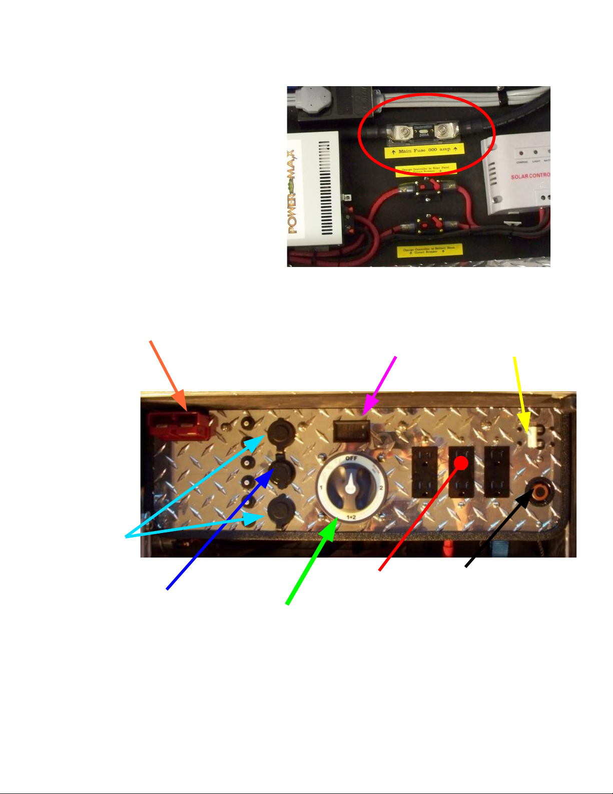
sockets for the appropriate devices, in addition to standard 120 volt AC house current.) he
inverter is protected internally from overheating and low battery voltage, and externally from
over-current draw by a 300 ampere ANL type fuse. he Model 5000 will sustain a continuous
5000 watts of current, and will briefly provide up to 18,000 surge watts, to start motors and
other inductive loads. he inverter relies on air flow around and through the unit to cool it,
therefore it is imperative that the inverter not be used with the enclosure door closed.
1

*A quick note on EMP
An EMP, or Electro-Magnetic Pulse is a devastating phenomenon that, while harmless to living
things, absolutely destroys anything electronic. t consists of extremely powerful electromagnetic fields
building and collapsing hundreds of thousands of times per second. This induces potentially huge
electric currents in anything that conducts electricity, causing components connected to said conductor
to burn out. An EMP can be caused by either a deliberate, high-altitude nuclear warhead detonation,
or can be caused naturally by a solar event called a Coronal Mass Ejection, or CME.
All Quantum Harvest power units are built into a specially designed enclosure, more
properly called a Faraday Cage, named after Michael Faraday, an early pioneer in
electromagnetic research. The purpose of a Faraday cage is to intercept and divert
electromagnetic energy away from the box's interior, thus protecting the contents.
The principles involved are fairly simple, but the proper execution is critical. n order
for the enclosure to be useful, it must have a door, but any opening larger than a square
centimeter or so allows too much energy to penetrate the interior, thus defeating the purpose of
the Faraday cage.
The solution to this conundrum is to gasket the door with a special type of conductive
gasket, mated to a copper or silver strip that is electrically bonded to the main box. The key is
to have very low electrical resistance between the door and the enclosure, with no gaps. This is
not as easy as it sounds, and requires special materials designed specifically for this
application.
My experience with Faraday apparatus comes from 8 years experience with very
powerful industrial machines called RF welders. These machines use extremely powerful and
focused bursts of electromagnetic energy to weld and form plastic parts. These machines
basically create a local EMP every time they fire, and it is critical that stray energy be confined
and dissipated safely to avoid damage to other sensitive electrical machinery.
2

Table of Contents
S ecifications.......................................................................................Page 4
Note on Batteries.................................................................................Page 5
Section 1............Ca acities and recommended usages.....................Page 6-7
Section 2............Controls/Circuit Protection Devices.......................Page 8-10
Section 3............External Ports and Connectors..............................Page 11-12
Section 4A.........General O eration and Routine Maintenance......Page 13
Section 4B.........Connecting and Using the Solar Panels..................Page 14
Section 4C.........Charger......................................................................Page 15
Section 5A.........Power Board Removal, Re-installation..................Page 16-18
Section 5B..........Battery Removal, Re-installation...........................Page 19-25
Section 5C.........Control Panel Removal, Re-installation.................Page 26-27
Contact Information............................................................................Page 28
Warranty Information.........................................................................Page 29
Addendum A...................Solar Panel Diode Re lacement................Page 30-31
3

Base Unit S ecifications
Assembled Dimensions: 57.5” Long (includes wagon tongue, base cabinet is 47”
Long), 24.75” Wide by 34.75” High
Assembled Weight: 800 lbs.
Inverter: AIMS PICOGLF60W24V230VS rue sine-wave, 24 volt
Battery Bank: 8 AGM Deep-Cycle Batteries, 110 amp/hrs each.
Battery Bank Ca acity: 880 Amp/hours; 10,560 Watt/hours
AC Charger: 50 Amp Smart Battery Charger
Solar Charger/Controller: Instapark 60 amp PWM- ype

4
In this manual, the following symbols are used to
highlight im ortant facts:
Denotes circumstances where failure to follow the procedures
outlined in the manual may result in property damage.
Denotes circumstances where failure to follow the procedures
outlined in the manual may result in personal injury or death.
Always remember that electricity is utterly devoid of mercy and
never grants second chances!
Note on Batteries
his Quantum Harvest power station is designed to use AGM batteries
that measure 12.91” Long, by 6.77” Wide by 9.29” High. he particular
battery model we use is the UB121100 110AH model. Other models of
similar dimensions and specifications will also work.
*Caution* Although the low voltage at the battery terminals
means that electrical shock or electrocution is im ossible,
nonetheless, batteries store an enormous amount of otential energy,
that if accidentally released by a short-circuit, can melt metal tools, start
fires and cause ersonal injury. Eye rotection MUST BE WORN
whenever working with batteries of this size, and extreme care must be
exercised at all times. Anything electrical is unforgiving of mistakes.
!Warning! Note that although the voltage at the battery
terminals is insufficient to shock a erson, the current coming
from the inverter rece tacles is 120 volt house current, and that
is indeed ca able of inflicting a severe, otentially fatal shock.
Always be sure that extension cords are not frayed or worn, and that all
equi ment lugged into the inverter is in a safe condition.

5
Section 1: Ca acities and recommended usages
his 5,000 watt model is the next-to-largest true sine-wave unit we currently produce,
and with it's premium, marine-grade AIMS inverter with proven soft-start technology, will
reliably start and power anything within it's capability, even fussy items that will not run with
cheaper, modified sine-wave inverters. It will run full-size refrigerators and freezers, table saws
and chop saws, as well as any hand-held tools, such as drills, grinders and circular saws, etc. It
will also, of course, power smaller items such as Vs, cell phones,laptops, tablets, etc.
his Model is available with a proprietary soft-start mechanism to augment the built-in
system in the inverter, which allows it to reliably start and power up to to a 5 hp air compressor,
or a 2 hp submersible well pump. It is NO recommended to power large resistive loads like
central air-conditioners,water heaters and electric space heaters.
Used within it's limits, this unit will provide many years of trouble-free service, and be a
joy to own and use. But like most things, if you push it beyond it's limits, you will be plagued
by expensive repairs and poor performance.
his machine contains a battery bank of eight, 110 amp/hour batteries, for a total
capacity of 880 amp/hrs. How much real power is that? If we multiply the 880 amp/hours by
the nominal voltage (12 volts), we get a capacity of 10,560 watt/hours (watts = volts times
amps). his machine will run a full-sized refrigerator or freezer for several days, even without
the solar panels hooked up.
On the next page is a partial list of common electrical appliances and their approximate
loads, provided in part by the good folks at: http://www.energy.gov
6

7

Section 2: Controls/Circuit Protection Devices
here is one main fuse, a 300 ampere ANL
type fuse, shown to the right, located beside
the inverter. here is one spare fuse
included in the spare parts kit. o replace
the fuse, first, be sure the main switch is
turned off, then, using a 9/16” wrench,
remove the two nuts. Lift the fuse out and
place the new one over the studs; reapply
the nuts, being careful to not over-tighten.
Detail of Main Control Panel
Anderson connector for external batteries Voltage/Charging am s meter 220 volt AC
breaker
12 Volt DC
cigarette
lighter-style
outlets
USB charger orts (2) 120 volt AC outlets 220 volt AC outlet
Main Switch; 4 ositions available.
Off osition isolates the inverter and control anel from the batteries.
Position #1 is the normal use osition in which the unit draws from the internal battery bank.
Position #1&2 is the osition used when using an external battery(s), and allows the unit to run
from both the internal battery bank and the external source .
Position #2 is not normally used, and allows the load to be run directly from an external source,
by assing the internal battery bank.
8

Detail of Main Panel Circuit Breakers
15 amp breakers (3)
for 120 volt outlets.
10 amp (2) for 12 volt
DC outlets
5 amp for USB
charger,
220 volt AC breaker
Detail of AC Charger
40 amp automotive-style fuses
here are no adjustments or maintenance required for the AC charger; all it's functions
are fully automatic.
9

Detail of Solar Charger/Controller
and related circuit-breakers
here are no adjustments or maintenance required for the solar charger; all it's functions
are fully automatic.
Right; he solar charge controller is
protected by 2, 70-amp circuit-breakers.
To avoid damage to the solar
controller, it is im ortant that it
be used in accordance with the
instructions on age 14.
10

Section 3: External Ports and Connectors
The external orts/connectors for attaching the ower cord for the AC charger and the solar
anels are located on the latch side of the unit.
External Connector Location
(Model 3000 shown, but Model 5000 ports and location are the same.)
AC Charger ort
Insert the plug into the socket with the silver tab on top, and turned slightly to the left. Push it in fully
and gently twist it clockwise until it latches. o remove, use your thumb to pull the silver tab toward
you, then twist the plug counter-clockwise and pull it out of the socket.
11

Solar Panel Connector Port
o connect, lift the cover, and
oriented as shown with the boss on
top, slide the connector into the
socket. Please note that the cover
has a latch-pawl to prevent the jack
from creeping out. o remove, lift
the cover slightly to disengage the
latch, and remove the jack.
(Although both connectors are shown connected in the upper photo for illustration
purposes, it is not recommended that both the AC charger and the solar charger operate
at the same time.)
12

Section 4A: General O eration and Maintenance
WARNING! The base unit is NOT water- roof, and must be
stored and used in a dry location. Wind-driven rain will ruin
the inverter, and worse, set u conditions where eo le or
ets may be electrocuted.
Also, lease take note that in addition to the above very real
danger, the warranty does not cover water or other weather-related
damage to any of the com onents!
o use the unit, unplug the AC charger cord if it is connected, then wheel the unit to a
convenient location. Open the cabinet door and turn the main switch clockwise to position #1
and then press the inverter start button to initialize the inverter. Connect any loads to the
appropriate receptacles. Be sure to keep the door open so as to allow adequate airflow for
inverter cooling.
nverter start switch
Note that it is not necessary to have the solar
panels connected in order to use the power
station, but if they are not connected (and in
direct sunlight), you will only have what
power is in the batteries. here is no easy way
to tell exactly how much charge remains in the
batteries, so the best measure we have is to watch the battery bank voltage, which is shown on
the control panel's digital display.
Battery voltage gradients change over time as the batteries age, but a good rule of thumb
is that 27 to 25.6 volts is a reading for a battery bank pretty much fully charged. When the
voltage drops to 25.2 to 24.8 volts, the batteries are usually about one half to two-thirds
discharged. Voltage of 24.5 to 24.1 mean that the battery is pretty much exhausted, and voltages
below 24 will cause the inverter to shut off. hese numbers are only approximate, experience is
still the best teacher!
Please note that the voltage readings, to be accurate, must be read under
a no-load condition. The voltage will be lower when the batteries are under
load.
13

Section 4B: Connecting and using solar anels.
Ste 1: Be sure both circuit-breakers to the solar charge controller are
switched off.
Ste 2: Connect the jack from the anels into the ort on the generator base
unit.
Ste 3: It is very im ortant to switch the charge controller to battery bank
circuit-breaker (bottom one) on first, then the charge controller to solar anel
circuit-breaker (u er one) on next.
Switch this breaker on
first.
Switch this breaker on
next.
(Breakers shown in off (open) position. To switch on, rotate the red levers down until they
latch. To switch off, press red button to left of red lever.)
14

Section 4C: AC Charger
When you are finished with the unit, unplug the solar panel assembly, coil the cable on
the brackets and stow the assembly in a safe place. Switch off the inverter, then turn the main
switch to the off position. Wheel the unit to a safe, indoor location, and plug the AC charger
cord into a wall socket and plug the other end into the appropriate socket on the side of the base
unit. Close and latch the cabinet door. Note that the main switch should be OFF. he AC
charger will automatically maintain the batteries at the optimum voltage as long as it is plugged
in. here is no need for further intervention.
Please note that the AC charger will charge the batteries even if the
main switch is off, but in order to use the inverter or other ower outlets, the
main switch MUST be switched to osition #1!
he only other maintenance needed besides keeping the batteries charged is to keep the
faces of the solar panels clean to improve their efficiency.
15

Maintenance and Re air Section
Section 5A: Power Board Assembly Removal and Re-
installation
All Quantum Harvest power stations feature a modular construction that allows faulty
components to be easily removed and returned to us for repair, without the necessity of having
to crate up the entire heavy unit and paying the costly shipping charges for an 800+ lb.
machine.
his model power station consists of, in addition to the casing and batteries, two such
removable modules; the power assembly, which contains the the inverter, chargers and related
components, and the control panel.
Removal of the ower assembly.
Tools Required: 9/16” and 1/2” socket or wrench, #2 Philli s Screwdriver
Main fuse nverter Main Power Cord
Ste 1: Remove these three knobs.
Ste 2: Remove the main fuse, then pull up the inverter main power cord to expose the twist-
lock connector; twist the two halves counter-clockwise and pull it apart, then lay the inverter
end beside the inverter. Lay the heavy black cable from the fuse block up and over the back of
the unit to get it out of the way.
It is absolutely im erative that the main fuse be removed
BEFORE un lugging any other cables to reclude any
ossibility of creating a short circuit!
16

Ste 3: Below; Remove the screws securing the plastic cable guards on the end of the inverter closest
to the control panel, and remove the guards. Using a 1/2” wrench or socket, remove the nuts and cables
from the DC side of the inverter.
Ste 4: Right;, Disconnect the 4 connectors
detailed below, and place all the cables up and
out of the way. uck the inverter and fuse
block cables down under the control panel to
avoid having them catch on the power board
during removal.
Ste 5: Below;
(The ower board assembly weighs over 120 lbs, so to avoid injury, or unit
damage, it is highly recommended that this ste be accom lished by 2
eo le.)
Using the handles provided, tilt the inverter side up and rotate the entire assembly up and out of
the case, being careful to avoid damaging the RF gasket around the case opening.
17

Reverse the above ste s to re-install.
IT IS VERY IMPORTANT THAT THE INVERTER CABLES NOT BE
CROSSED. BE ABSOLUTELY SURE THAT THE RED CABLE
CONNECTS TO THE RED TERMINAL AND THE BLACK CABLE
TO THE BLACK TERMINAL. THE INVERTER IS NOT
PROTECTED FROM CROSS-POLARITY OF THE DC INPUTS, AND
SEVERE EQUIPMENT DAMAGE WILL RESULT IF THEY ARE
CROSSED!
18
Table of contents
Other Quantum Harvest Inverter manuals