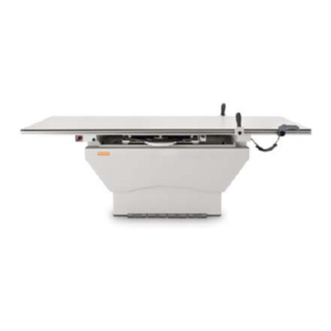
Quantum QT-740 User manual

Service Manual
Fixed/Elevating
Float-Top
Radiographic Tables
™
Models QT-740 and QT-750
Manual Part No. DC30-007 Revision Q

EU Authorized Representative:
Medizintechnik Berlin GmbH
Altentreptower, Strasse 59
12683 Berlin - Germany
Phone: +49-302-82 4726
Fax: +49-302-82 6382
E-mail: Medizintechnik.[email protected]
This manual is copyrighted and all rights are reserved. No portion of this document
may be copied, photocopied, reproduced, translated, or reduced to any electronic
medium or machine readable form without prior consent in writing from Quantum
Medical Imaging, (QMI)
Copyright© 2007 QMI
Made in U.S.A.
Quantum Medical Imaging,
2002-B Orville Drive North
Ronkonkoma, New York 11779 USA
Phone: (631) 567-5800
Fax: (631) 567-5074
E-mail: [email protected]
www.quantummedical.net
THE ORIGINAL VERSION OF THIS MANUAL DATED DECEMBER 7, 2000 HAS BEEN
DRAFTED IN THE ENGLISH LANGUAGE BY QUANTUM MEDICAL IMAGING

Models QT-740 & QT-750 - Service Manual Revision Q
Quantum Medical Imaging i
Revision History
REVISION DATE TYPE OF MODIFICATION
A 12/07/00 Initial Release.
B 1/5/01 Added long. magnet adjustment, tabletop width
adjustment, DC Motor Driver Bd. replacement procedure
C 2/22/01 Incorporated ECO’s 0241, 0242, 0245, 0247, 0256, 0285
D 4/19/01 Incorporated ECO 0335
E 5/17/01 Modified table mounting instructions
F 8/6/01 Incorporated ECO’s 0294, 0417, 0447, 0451, 0492
G 11/6/01 Incorporated ECO’s 0544, 0572, 0574, 0599
H 3/15/02 Incorporated ECO’s 0706, 0715, 0741, 0749, 0762, 0782
J 7/1/02 Incorporated ECO’s 0449, 0820, 0825, 0845, 0879, 0897
K 8/1/02 Incorporated ECO 0853
L 6/20/03 Incorporated ECO 0894, 1025, 1038, 1116, 1232
M 4/29/03 Incorporated ECO 1189, 1314, 1328, 1359, 1436, 1447
N 9/17/04 Incorporated ECO 1482, 1525
P 4/28/06 Incorporated ECO 1583, 1584, 1605, 1689, 1716
Q 9/7/07 Incorporated ECO 1807, 1850, 1859, 1880
Page
Number Rev Page
Number Rev Page
Number Rev
i - iv Q
1-1 thru 1-8 Q
2-1 thru 2-24 Q
3-1 thru 3-6 Q
4-1 thru 4-34 Q
5-1 thru 5-9 Q

Revision Q Models QT-740 & QT-750 - Service Manual
ii Quantum Medical Imaging
Revision History
THIS PAGE INTENTIONALLY LEFT BLANK

Table of Contents
Models QT-740 & QT-750 - Service Manual Revision Q
Quantum Medical Imaging iii
Chapter 1 Specifications
PHYSICAL SPECIFICATIONS .................................................................................1-3
TABLETOP SPECIFICATIONS .............................................................................1-3
TABLE BASE SPECIFICATIONS ...........................................................................1-3
IMAGE RECEPTOR SPECIFICATIONS ..................................................................1-3
SYSTEM SPECIFICATIONS .................................................................................1-4
ELECTRICAL SPECIFICATIONS ..............................................................................1-4
SYSTEM OPTIONS ................................................................................................1-4
SYSTEM OPERATING ENVIRONMENT ....................................................................1-4
NON-OPERATING ENVIRONMENT .........................................................................1-4
Chapter 2 Assembly & Installation
OVERVIEW ..........................................................................................................2-3
UNPACKING ........................................................................................................2-3
TABLE ASSEMBLY ................................................................................................2-3
POSITIONING THE TABLE BASE ........................................................................2-3
ELECTRICAL CONNECTIONS ..............................................................................2-4
Power Input Connections (Power Cord with Plug Configuration) ....................2-4
Power Input Connections (Permanent Wiring Configuration) .........................2-4
Re-Configuring AC Line Input Transformer (115 VAC/230 VAC Input) ............2-6
Bucky Power Input Connections ..................................................................2-6
PBL Interlock Cable Connections .................................................................2-6
TABLE LEVELING AND MOUNTING ........................................................................2-8
MODEL QT-740 - LEVELING AND MOUNTING INSTRUCTIONS .............................2-8
MODEL QT-750 - LEVELING AND MOUNTING INSTRUCTIONS .............................2-8
ALIGNMENT PROCEDURES ...................................................................................2-9
IMAGE RECEPTOR/COLLIMATOR X-RAY ALIGNMENT ..........................................2-9
TABLETOP ASSEMBLY/INSTALLATION ............................................................. 2-11
REDUCING THE TABLE TOP HEIGHT (MODEL QT-750 ONLY) ............................ 2-14
OPERATOR CONTROL HANDLE ASSEMBLY INSTALLATION ................................ 2-16
OPERATIONAL CHECKS AND ADJUSTMENTS ........................................................ 2-17
CHECKING TABLE FLOAT-TOP OPERATION ...................................................... 2-17
CHECKING UP/DOWN OPERATION (MODEL QT-750 ONLY) ............................... 2-17
TABLE UP/DOWN SPEED ADJUSTMENT (MODEL QT-750 ONLY) ........................ 2-18
PEDAL DISABLE SWITCH OPERATIONAL CHECK ............................................... 2-18
CHECKING THE OBSTRUCTION SENSORS (ELEVATING TABLE ONLY) ................ 2-19
RECEPTOR CABINET LOCKING MAGNET CHECK ...............................................2-20
POSITIVE BEAM LIMITATION (PBL) COLLIMATORS .......................................... 2-21
MODEL QT-750 COVERS INSTALLATION/ADJUSTMENT PROCEDURE ..................... 2-21
MODEL QT-740 COVERS INSTALLATION PROCEDURE ..........................................2-23

Table of Contents
Revision Q Models QT-740 & QT-750 - Service Manual
iv Quantum Medical Imaging
Chapter 3 Theory of Operation
OVERVIEW ..........................................................................................................3-3
MODEL QT-740 TABLE ......................................................................................3-3
Power Distribution ......................................................................................3-3
Float Control ..............................................................................................3-4
Foot Pedal Disable Circuit ...........................................................................3-4
Receptor Cabinet Lock ................................................................................3-4
MODEL QT-750 TABLE ......................................................................................3-4
Power Distribution ......................................................................................3-4
Voltage Regulation .....................................................................................3-5
Float Control ..............................................................................................3-5
Foot Pedal Disable Switch ...........................................................................3-5
Positive Beam Limitation .............................................................................3-5
Receptor Cabinet Lock ................................................................................3-5
Emergency Stop Switch ..............................................................................3-5
Chapter 4 Service Instructions
OVERVIEW ..........................................................................................................4-3
SERVICE MAINTENANCE ...................................................................................4-4
Visual Inspection ........................................................................................4-4
Functional Check for Model QT-750 Elevating Tables ....................................4-4
Lubrication ................................................................................................4-5
Float Top Locking Magnet Check .................................................................4-6
TROUBLESHOOTING PROCEDURES ....................................................................4-8
REMOVAL/REPLACEMENT PROCEDURES ...........................................................4-13
Replacing the Drive Belt (Model QT-750 Tables Only) .................................4-13
Replacing the Sync Belt (Model QT-750 Tables Only) ..................................4-14
Replacing the DC Motor (Model QT-750 Tables Only) ..................................4-16
Replacing the DC Motor Driver Board A2 (Model QT-750 Tables Only) ..........4-18
Receptor Cabinet Removal/Replacement ....................................................4-22
Cassette Tray Removal Procedure .............................................................4-23
REPLACEMENT PARTS AND ORDERING INFORMATION .....................................4-24
ORDERING INFORMATION ..............................................................................4-27
Chapter 5 Diagrams
Model QT-740 Radiographic Table Wiring Diagram ..............................................5-3
Model QT-750 Radiographic Table Wiring Diagram ..............................................5-4
4-Way Table Control Board A1 (AY40-017T) .......................................................5-5
6-Way Table Control Board A1 (AY40-030T) Test Point Diagram ..........................5-6
Table Base Plate Mounting Hole Locations ..........................................................5-7
Installing Digital Image Receptor Using QT-FCD Mounting Bracket .......................5-8
Installing Digital Image Receptor Using QT-DDS Slide Mounting Bracket ...............5-9
Chapter
1-1
SPECIFICATIONS
1

1-2

Chapter 1 Specifications
Models QT-740 & QT-750 - Service Manual Revision Q
Quantum Medical Imaging 1-3
PHYSICAL SPECIFICATIONS
The following are physical specifications of the radiographic tables:
TABLETOP SPECIFICATIONS
Length: 85.0 inches (2159.0 mm)
Width: 35.5 inches (901.7 mm)
Height (Model QT-740): 32.5 inches (825.5 mm)
Height (Model QT-750):
Raised: 32.5 inches (825.5 mm) *(see note 1)
Lowered: 21.0 inches (533.4 mm)
Tabletop Travel:
Longitudinal: 32 inches (812.8 mm)
Lateral: 10 inches (254 mm)
Tabletop Material: Fiber-resin (phenolic)
Tabletop X-ray Density: 1.0 mm Aluminum
Tabletop-to-Film Plane
Distance: approx. 2.75 inches (69.9 mm)
*Note 1: To compensate for low ceilings, maximum raised table height can be
decreased by up to 2 inches less (see Assembly & Installation Chapter
for instructions)
TABLE BASE SPECIFICATIONS
Width: 48.0 inches (1219.2 mm)
Depth: 26.0 inches (660.4 mm)
Maximum Patient Load (with
non-digital image receptor): 650 lbs. (295 kg)
Maximum Patient Load (with
non-sliding digital image
receptor): 600 lbs. (272.2 kg)
Maximum Patient Load (with
sliding digital image receptor): 550 lbs. (249.5 kg)
IMAGE RECEPTOR SPECIFICATIONS
Compatible With: Grid Cabinet, Bucky, ACL Bucky
Receptor Longitudinal Travel: 20.0 inches (508.0 mm) **(see note 2)
**Note 2: 17.00 inches (431.8 mm) of receptor travel with QT-DDS option

Chapter 1 Specifications
Revision Q Models QT-740 & QT-750 - Service Manual
1-4 Quantum Medical Imaging
SYSTEM SPECIFICATIONS
Tube Stand Compatibility: Compatible with all Quantum Medical Imaging
tube stands and overhead tube cranes
Overall Weight:
Model QT-740: 350.0 lbs. (158.8 kg)
Model QT-750: 500.0 lbs. (226.8 kg)
ELECTRICAL SPECIFICATIONS
Input Power: 115 VAC (±10%), 15 Amps, 50/60 Hz
230 VAC (±10%), 10 Amps, 50/60 Hz
Mode of Operation:
Model QT-740: Continuous
Model QT-750: Intermittent Operation (80 cycles/hour max.)
Momentary Current:
Model QT-740: 1.0 Amp
Model QT-750: 7.0 Amps
Long Term Current:
Model QT-740: 0.20 Amp
Model QT-750: 0.25 Amp
Locking System Power: 24 VDC/6.0 Amps
SYSTEM OPTIONS
• R90-CB: Abdominal compression band
• Lateral cassette holder (for cross-table work)
• QT-DDS: Digital Drawer Slide (see Figure 1-3 for specifications)
• QT-BMP4: Rubber Corner Bumpers (set of four)
• QT-PLS: Patient Support Strap
• R-DLMP: Receptor Tray for Canon Imager allows images in length-wise
(Portrait) and cross-wise (Landscape) modes.
SYSTEM OPERATING ENVIRONMENT
Ambient Temperature: +10°C to +40°C
Relative Humidity: 30 to 75%, non-condensing
Atmospheric Pressure: 700 hPa to 1060 hPa
NON-OPERATING ENVIRONMENT
Ambient Temperature: -18°C to +70°C
Relative Humidity: 20 to 95%, non-condensing
Atmospheric Pressure: 500 hPa to 1060 hPa

Chapter 1 Specifications
Models QT-740 & QT-750 - Service Manual Revision Q
Quantum Medical Imaging 1-5
Figure 1-1. Model QT-740 Table Configuration Diagram
85.00
87.00 (MIN.)
TO INSTALL
TABLETOP
(ON EITHER
LEFT OR RIGHT
SIDE OF TABLE)
35.5
34.00
26.00
10.79
PC.G.
32.50
2.75
24.04 PC.G.
15.19
PC.G.

Chapter 1 Specifications
Revision Q Models QT-740 & QT-750 - Service Manual
1-6 Quantum Medical Imaging
Figure 1-2. Model QT-750 Table Configuration Diagram
85.00
34.00
32.50
21.00
2.75
NOTE: CENTER-OF-GRAVITY (C.G.)
IS CALCULATED WITH TABLE
FULLY ELEVATED AND
WITHOUT PATIENT.
24.04 PC.G.
35.5
26.00
10.79
PC.G.
32.50

Chapter 1 Specifications
Models QT-740 & QT-750 - Service Manual Revision Q
Quantum Medical Imaging 1-7
Figure 1-3. Table with QT-DDS Option (Slide-Out Canon Digital Receptor)

Chapter 1 Specifications
Revision Q Models QT-740 & QT-750 - Service Manual
1-8 Quantum Medical Imaging
THIS PAGE INTENTIONALLY LEFT BLANK

Chapter
2-1
ASSEMBLY &
INSTALLATION
2

2-2

Chapter 2 Assembly & Installation
Models QT-740 & QT-750 - Service Manual Revision Q
Quantum Medical Imaging 2-3
OVERVIEW
Preparing the table for operation requires completion of the following tasks:
• Positioning the Table Base
• Making the Electrical Connections
• Alignment Procedures
• Tabletop Assembly/Installation
• Checking Table Operation
• Installing the Covers
UNPACKING
Open crate or carton marked "packing list enclosed" first. Remove packing list and
use it as a guide to open the remaining cartons. Do not dispose of packing material
until packing list is matched with actual parts received. Should there be a shortage or
damage, notify manufacturer’s customer service department immediately. The manu-
facturer is relieved of any responsibility for damage during shipment after unit is
picked up by the carrier.
TABLE ASSEMBLY
The radiographic table is shipped with most of its major components assembled.
However, the tabletop assembly must be attached to the base assembly and the cov-
ers must be installed. After the table is assembled, an operational check is per-
formed. (This check is required only on Model QT-750 radiographic tables.)
On systems equipped with QT-FCD option (fixed mount for Canon Digital Image
Receptor), refer to Figure 5-5 in Chapter 5, Diagrams for instructions on installing the
digital image receptor in the table.
On systems equipped with QT-DDS option (drawer slide mount for Canon Digital
Image Receptor), refer to Figure 5-6 in Chapter 5, Diagrams for instructions on
installing the digital image receptor in the table.
POSITIONING THE TABLE BASE
Place the table base in the approximate location where it will be mounted.
Ensure that the floor below the table is level. When positioning the table base,
ensure there is a minimum clearance of 87 inches from the outer edge of Bearing
Rail to the wall on either side of the table (see Figures 1-1 and 1-2). This allows
for installation of the tabletop rails following table mounting. If enough clearance
is provided, proceed to the "Electrical Connections" paragraph in this chapter.
If there is not enough clearance on either side to install the tabletop after the
table is mounted to the floor, the tabletop must be installed prior to mounting the
table. To install the tabletop, proceed to the paragraph entitled "Tabletop Assem-
bly/Installation" before performing the next procedure.
NOTE
Examine all car-
tons and crates
carefully at time
of delivery. If
damageis appar-
ent, have deliv-
ery driver write a
"Damaged Ship-
ment Note" on
copies of freight
bill, sign it, and
file appropriate
carrier claim.
Should you dis-
cover concealed
damage, immedi-
ately notify the
transporting
agent and ask
for an
"Inspection of
Damage". Carrier
will not accept
concealed dam-
age claim if filed
after 15 days
from date of
receipt of mer-
chandise.

Chapter 2 Assembly & Installation
Revision Q Models QT-740 & QT-750 - Service Manual
2-4 Quantum Medical Imaging
ELECTRICAL CONNECTIONS
CAUTION! This equipment contains electrostatic
sensitive devices. Observe proper grounding pre-
cautions before handling components or printed
circuit boards.
Power Input Connections (Power Cord with Plug Configuration)
For 115 VAC installations, a 25-foot power cord with a hospital-grade
plug is factory pre-wired to the table. For 230 VAC installations, a 25-foot
"HAR" power cord is factory pre-wired to the table; the installer must
attach the proper plug depending on receptacle type used at installation
site. If a line cord with plug is provided by the facility, it must have a 16
AWG minimum cord (Type SJT or equivalent) and a hospital grade plug.
Connect plug to hospital grade receptacle only. The power supply line
input connection is fused internal to the table (2A for 115 VAC line input,
1A for 230 VAC line input for Model QT-740 tables; 6A for 115 VAC line
input, 3A for 230 VAC line input for Model QT-750 tables).
Power Input Connections (Permanent Wiring Configuration)
CAUTION! When AC power source is single-phase
(e.g., US 115 V and European 230 V), do not fuse
the neutral leg if permanently installed. Replace
neutral wire Fuse F1 with dummy fuse, supplied
with table. When two-phase AC power is used
(e.g., US 240 V), both lines must be fused. For fuse
charts see Chapter 5 Diagrams, Figure 5-1 for
QT-740 Table and Figure 5-2 for QT-750 Table.
The table can be powered from independently fused power source
(mains) or from specified equipment, such as an X-ray generator. All
electrical connections must be made by a qualified electrician in compli-
ance with NEC or local code requirements. Refer to QT-740 or QT-750
Interconnection Diagram in Chapter 5, Diagrams and proceed as follows:
1. To connect external wires to table, either bring cables through the
Rear Bottom Cover access opening or, if conduit and flush floor box is
run beneath the table, through the large 6" x 5" opening in the table
base.

Chapter 2 Assembly & Installation
Models QT-740 & QT-750 - Service Manual Revision Q
Quantum Medical Imaging 2-5
2. Route power input to Terminal Block TB1 (located on table base) ter-
minals TB1-1 (line), TB1-2 (neutral) and TB1-3 (GND) as
shown in Figure 2-1.
Figure 2-1. Connecting Input Power Cable
3. Connect system ground wires as shown in Figure 2-4.
Figure 2-2. System Ground Wire Connections
TERMINAL
BOARD TB2
TERMINAL
BOARD TB1
(REAR VIEW)
POWER
INPUT CABLE

Chapter 2 Assembly & Installation
Revision Q Models QT-740 & QT-750 - Service Manual
2-6 Quantum Medical Imaging
Re-Configuring AC Line Input Transformer (115 VAC/230 VAC
Input)
Typically, the AC line input transformer is configured at factory in accor-
dance with user facility electrical requirements (i.e., 115 VAC or 230
VAC). If it is necessary to re-configure from 115 VAC to 230 VAC, or 230
VAC to 115 VAC, make connections at terminal block TB1, located on
table base, as shown in Figure 2-3 and Model QT-740 and QT-750 Radio-
graphic Table Wiring Diagrams in Chapter 5, Diagrams.
In addition, on Model QT-740 tables:
• For 115 VAC line input, the rating of fuse F2 and F1 should be 2
Amps, 250V slow-blow (see FFigureigure 5-1, Chapter 5, Diagrams
for fuse applications chart.)
• For 230 VAC line input Model QT-750 tables, the rating of fuse F2
and F1 should be 1 Amp, 250V slow-blow
On Model QT-750 tables:
• For 115 VAC line input, the rating of fuse F2 (and F1 if two-phase
AC input) should be 6 Amps, 250V slow-blow
• For 230 VAC line input Model QT-750 tables, the rating of fuse F2
and F1 should be 3 Amps, 250V slow-blow(see Figure 5-2, Chapter
5, Diagrams for fuse applications chart.)
CAUTION! A "dummy fuse" should be installed in
F1 fuseholder on all one-phase (with neutral) AC
(Permanently Installed hard wire mains) input
configurations as shown in Models QT-740 and
QT-750 Radiographic Table Wiring Diagrams (see
Chapter 5, DIAGRAMS).
Bucky Power Input Connections
To connect bucky wiring to table, route bucky cable through rear bottom
cover access opening to Terminal Block TB2 (see Figure 2-1). Refer to Q-
740 and QT-750 Table Wiring Diagrams in Chapter 5, Diagrams and to
bucky manufacturer’s installation manual (provided with system) for spe-
cific bucky wiring information.
PBL Interlock Cable Connections
On Model QT-750 tables using PBL interlock, connect PBL cable in accor-
dance with QT-740 and QT-750 Table Wiring Diagrams (refer to Chapter
5, Diagrams).
Other manuals for QT-740
2
This manual suits for next models
1
Table of contents
Other Quantum Medical Equipment manuals

Quantum
Quantum QT-740 User manual

Quantum
Quantum QT-730 Series User manual

Quantum
Quantum ODYSSEY HF Series User manual

Quantum
Quantum QS-550 User manual

Quantum
Quantum QT-710 User manual

Quantum
Quantum QW-400 Series User manual

Quantum
Quantum QS-550 User manual

Quantum
Quantum QT-740 User manual

Quantum
Quantum QS-500 Series User manual