Quantum ODYSSEY HF Series User manual

Service Manual
ODYSSEY, Q-VISION
HF Series™
X-ray Generators
™
Manual Part No. DC30-011 Revision W

This manual is copyrighted and all rights are reserved. No portion of this document
may be copied, photocopied, reproduced, translated, or reduced to any electronic
medium or machine readable form without prior consent in writing from Quantum
Medical Imaging, LLC. (QMI)
This Service Manual is incomplete without Operator’s Manual part number DC30-010.
Copyright© 2010 QMI
Made in U.S.A.
Quantum Medical Imaging, LLC
2002-B Orville Drive North
Ronkonkoma, NY 11779-7661 USA
Phone: (631) 567-5800
Fax: (631) 567-5074
E-mail: [email protected]
www.quantummedical.net
EU Authorized Representative:
Medizintechnik Berlin GmbH
Altentreptower, Strasse 59
12683 Berlin - Germany
Phone: +49-302-82 4726
Fax: +49-302-82 6382
E-mail: Medizintechnik.Berlin.GmbH@t-online.de

Revision History
HF Series X-ray Generators - Service Manual Revision W
Quantum Medical Imaging i
REVISION DATE TYPE OF MODIFICATION
E 1/12/02 Incorporated ECO 0647, 0651, 0687
F 2/25/02 Incorporated ECO 0714, 0718, 0738, 0742
G 5/15/02 Incorporated ECO 0642, 0748, 0753, 0770, 0787, 0803, 0809,
0821, 0827, 0829, 0830, 0847, 0859, 0881, 0888
H 9/26/02 Incorporated ECO 0787
J 11/11/02 Incorporated ECO 0936, 1003, 1009, 1010, 1017, 1028, 1030
K 3/31/03 Incorporated ECO 1093, 1102, 1103, 1107, 1115, 1124, 1146
L 7/11/03 Incorporated ECO 1255, 1256
M 7/29/03 Incorporated ECO 1269, 1270, 1272
N 12/19/03 Incorporated ECO 1144, 1216, 1347, 1359, 1362, 1380, 1383,
1400
P 9/10/04 Incorporated ECO 1346, 1438, 1485, 1518
Q 4/22/05 Incorporated ECO 1565, 1570, 1600, 1606, 1607
R 12/20/05 Incorporated ECO 1660, 1663, 1679
S 5/22/07 Assigned new part number to Non-QMI HSS version manual;
Incorporated ECO 1697, 1715, 1757, 1794, 1890
T 5/8/2008 Incorporate ECO 1895, 1920, 1932, 1977, 1985
U 11/21/2008 Incorporate ECO 2045, 2050, 2068, 2093, 2105
V 9/1/2009 Incorporate ECO 1980, 2160, 2166, 2169
W 1/15/2010 Incorporate ECO 2220, 2228, 2276
Page
Number Rev Page
Number Rev Page
Number Rev
i thru xii W 4-1 thru 4-20 W B-1 thru B-56 W
1-1 thru 1-22 W 5-1 thru 5-96 W C-1 thru C-7 W
2-1 thru 2-56 W 6-1 thru 6-67 W D-1 thru D-66 W
3-1 thru 3-72 W A-1 thru A-16 W

Revision History
Revision W HF Series X-ray Generators - Service Manual
ii Quantum Medical Imaging
THIS PAGE INTENTIONALLY LEFT BLANK

Table of Contents
HF Series X-ray Generators - Service Manual Revision W
Quantum Medical Imaging iii
CHAPTER 1 - SPECIFICATIONS
SYSTEM CONFIGURATIONS ................................................................. 1-3
PHYSICAL SPECIFICATIONS ................................................................. 1-5
GENERATOR CABINET SPECIFICATIONS ......................................... 1-5
OPERATOR CONTROL PANEL SPECIFICATIONS ............................... 1-5
ODYSSEY HF Control Panel: ..................................................... 1-5
Q-VISION HF Control Panel: .................................................... 1-5
SYSTEM SPECIFICATIONS .............................................................. 1-5
POWER REQUIREMENTS ...................................................................... 1-6
SINGLE-PHASE X-RAY GENERATORS ............................................... 1-7
25 kW Single Phase (Model QG-25) ........................................... 1-7
25 kW Single Phase (Model QG-25-5)* ...................................... 1-7
32 kW Single Phase (Model QG-32) ........................................... 1-7
32 kW Single Phase (Model QG-32-5)* ...................................... 1-7
40 kW Single Phase (Model QG-40) ........................................... 1-8
40 kW Single Phase (Model QG-40-5)* ...................................... 1-8
32 kW Single Phase, Stored Energy ........................................... 1-8
40 kW Single Phase, Stored Energy ........................................... 1-8
50 kW Single Phase, Stored Energy ........................................... 1-8
THREE-PHASE X-RAY GENERATORS ................................................ 1-9
32 kW Three Phase (Model QG-32-2) ........................................ 1-9
32 kW Three Phase (Model QG-32-3) ........................................ 1-9
40 kW Three Phase (Model QG-40-2) ........................................ 1-9
40 kW Three Phase (Model QG-40-3) ........................................ 1-9
50 kW Three Phase (Model QG-50-2) ........................................ 1-9
50 kW Three Phase (Model QG-50-3) ........................................ 1-9
65 kW Three Phase (Model QG-65) ..........................................1-10
80 kW Three Phase (Model QG-80) ..........................................1-10
HIGH-SPEED STARTER POWER REQUIREMENTS ............................1-10
GENERATOR AUXILIARY POWER SUPPLIES ..........................................1-15
PERFORMANCE SPECIFICATIONS ........................................................1-15
SYSTEM OPTIONS ..............................................................................1-19
SYSTEM OPERATING ENVIRONMENT ...................................................1-19
NON-OPERATING ENVIRONMENT ........................................................1-20
CHAPTER 2 - ASSEMBLY & INSTALLATION
OVERVIEW .......................................................................................... 2-3
PRE-INSTALLATION GUIDELINES ................................................... 2-3
Verify Equipment Location ........................................................ 2-3
Electrical Requirements ............................................................ 2-5
UNPACKING .................................................................................. 2-5
INSTALLATION .................................................................................... 2-6
REQUIRED TOOLS AND MATERIALS ............................................... 2-6

Table of Contents
Revision W HF Series X-ray Generators - Service Manual
iv Quantum Medical Imaging
CHAPTER 2 - ASSEMBLY & INSTALLATION (CONT’D)
GENERATOR CABINET SETUP ......................................................... 2-6
Transformer Line Tap Adjustment (Single Phase Non-SE Systems) 2-8
Transformer Line Tap Adjustment (Single Phase SE Systems) ....2-10
AC Input (Mains) Connection ...................................................2-12
High Voltage (H.V.) Tank ........................................................2-15
High Voltage Cables ................................................................2-18
INTERFACE BOARD SETTINGS & CONNECTIONS ............................2-21
Door Interlock Switch Connection ............................................2-22
"In Use" Light Switch Connection .............................................2-22
Collimator Connections ............................................................2-23
Tube Stand/Peripheral Equipment Connections .........................2-23
Internal +28 VDC Power Supply Option (QG-28VPS) .................2-23
Tube Rotor Boost Voltage Verification (Systems without
High (Dual) Speed Starter Option) ..........................................2-24
RADIOGRAPHIC SYSTEM EQUIPMENT CONNECTIONS ....................2-25
Tube Rotor Cable (Systems without High (Dual) Speed
Starter Option) ......................................................................2-25
Tube Rotor Cable (Systems with AID External High
Speed Starter QG-HSS Option Only) ........................................2-27
Tube Rotor Cable (Systems with Internal High Speed
Starter Q-HSS Option Only) ....................................................2-30
Table/Wall Bucky Connections .................................................2-34
Table/Wall Ion Chamber Connections (AEC Option Only) ...........2-34
Interfacing to Canon Digital Radiographic Receptor
(When Applicable) .................................................................2-35
Interfacing to CMT Digital Radiographic Receptor
(When Applicable) .................................................................2-36
Interfacing to Siemens Ion Chambers (When Applicable) ...........2-36
Interfacing to Pausch Tomography System (When Applicable) ...2-39
OPERATOR CONTROL PANEL SETUP ..............................................2-41
ODYSSEY Operator Control Panel ............................................2-41
OCP Pedestal Mounting (QG-PDL Option) .................................2-41
OCP Wall Mounting (QG-WM Option) .......................................2-43
Q-VISION Operator Control Panel ............................................2-44
Integrated Workstation Operator Control Panel .........................2-46
Optional Remote Expose Switch Connection .............................2-47
INITIAL POWER UP ......................................................................2-47
TRANSFORMER TAP VALIDATION ..................................................2-48
Q-VISION OPERATOR CONTROL PANEL - NETWORK
SETTINGS VERIFICATION ............................................................2-49
ROTOR DRIVE BOARD A10 (AY40-013T) PERFORMANCE
VERIFICATION ............................................................................2-55
CHAPTER 3 - CALIBRATION
OVERVIEW .......................................................................................... 3-3
REQUIRED TOOLS AND MATERIALS ............................................... 3-3

Table of Contents
HF Series X-ray Generators - Service Manual Revision W
Quantum Medical Imaging v
CHAPTER 3 - CALIBRATION (CONT’D)
SYSTEM CONFIGURATION/CALIBRATION ..............................................3-3
ACCESSING SERVICE MODE ...........................................................3-4
SYSTEM CONFIGURATION ..............................................................3-6
Printer On/Off Setting ...............................................................3-7
Generator Configuration/Derating Settings .................................3-8
AEC Setting .............................................................................3-9
Rotor Drive Setting .................................................................3-10
Edit Facility/Welcome Facility Utility .........................................3-11
Tube Type Setting ..................................................................3-12
Edit Digital Settings ................................................................3-13
Ion Chamber/Receptor Configuration .......................................3-14
Tomo Setting .........................................................................3-18
SYSTEM SETTINGS ......................................................................3-21
Set Date Screen .....................................................................3-22
Set Time Screen .....................................................................3-23
Film/Screen Defaults Screen ...................................................3-23
APR Format Setting ................................................................3-25
Language Setting ...................................................................3-26
Back Up MAS Setting ..............................................................3-27
Generator Timeout Setting ......................................................3-28
Date/Time Format Setting ......................................................3-28
SYSTEM CALIBRATION .................................................................3-29
GENERAL CALIBRATION PROCEDURE NOTES ................................3-32
Film Speed Setting on non-AEC Systems ..................................3-33
A/D Calibration ......................................................................3-34
kV Calibration Function ...........................................................3-37
Filament Offset Calibration ......................................................3-39
MA Calibration .......................................................................3-43
AEC CALIBRATION .......................................................................3-46
AEC Calibration Procedures .....................................................3-48
NON-AEC REPRODUCIBILITY VERIFICATION .................................3-66
AEC REPRODUCIBILITY VERIFICATION (ONLY PERFORM
ON UNITS EQUIPPED WITH QG-AEC OPTION) ..............................3-67
NON-AEC LINEARITY VERIFICATION .............................................3-67
AEC LINEARITY VERIFICATION (ONLY PERFORM ON
UNITS EQUIPPED WITH QG-AEC OPTION) ...................................3-68
MAXIMUM DEVIATION: KVP, TIME, MA, MAS .................................3-68
CHAPTER 4 - THEORY OF OPERATION
OVERVIEW ..........................................................................................4-3
OPERATOR CONTROL PANEL CIRCUIT ............................................4-3
Microcontroller U3 Operation .....................................................4-3
Flash Memory U2 .....................................................................4-3
EEPROM U17 Operation ............................................................4-4
LCD Controller U12 Operation ...................................................4-4

Table of Contents
Revision W HF Series X-ray Generators - Service Manual
vi Quantum Medical Imaging
CHAPTER 4 - THEORY OF OPERATION (CONT’D)
Switching Power Supply Circuit ................................................. 4-5
Front Panel Key Activation Detection Circuit ............................... 4-5
Jumpers Installation ................................................................. 4-5
TechVision Compatibility .......................................................... 4-5
GENERATOR LOGIC CIRCUIT ......................................................... 4-5
Generator/OCP Communication ................................................ 4-6
Master and Slave Microcontroller Operation ............................... 4-6
FILAMENT CONTROL REGULATOR CIRCUIT .................................... 4-7
KVP & FILAMENT CONTROL CIRCUIT .............................................. 4-7
LINE MONITOR CIRCUIT (NON-SE SINGLE-PHASE AND
THREE-PHASE SYSTEMS) .............................................................. 4-8
Input Line Monitor Circuit ......................................................... 4-8
Capacitor Discharge Circuit ....................................................... 4-9
Auto-Shutoff Circuit ................................................................. 4-9
Three-Phase Line Monitor Circuit .............................................4-10
LINE MONITOR CIRCUIT (STORED ENERGY SYSTEMS) ...................4-10
Battery Monitor Circuit ............................................................4-10
Storage Capacitor Discharge Circuit .........................................4-10
Generator Auto-Shutoff Circuit .................................................4-11
Battery Charger Circuit ............................................................4-11
POWER SUPPLY CIRCUIT ..............................................................4-12
+48 VDC Power Supply ...........................................................4-12
+15 VDC Power Supply ...........................................................4-12
+24 VDC Power Supply ...........................................................4-12
ROTOR BOARD CIRCUIT (NON-HIGH SPEED STARTER SYSTEMS) ...4-13
ROTOR BOARD CIRCUIT (QUANTUM INTERNAL HIGH
SPEED STARTER SYSTEMS) .........................................................4-13
HSS Control Board A20A1 (AY40-035S) ....................................4-14
HSS Drive Board A20A2 (AY40-036S) .......................................4-15
AEC BOARD CIRCUIT ....................................................................4-16
Standard Type AEC .................................................................4-16
Universal Type AEC .................................................................4-17
+300 VDC Power Supply .........................................................4-18
AEC Control Circuitry ...............................................................4-18
Tomography Circuitry ..............................................................4-20
CHAPTER 5 - SERVICE INSTRUCTIONS
OVERVIEW .......................................................................................... 5-3
DISPOSAL OF BATTERIES AND ACCUMULATORS
(DIRECTIVE 2006/66/EC) .............................................................. 5-3
SERVICE MAINTENANCE ................................................................ 5-4
Visual Inspection ..................................................................... 5-4
TROUBLESHOOTING ...................................................................... 5-5
Warning Messages ................................................................... 5-5
Error Codes ............................................................................. 5-5
Optional +28 VDC Power Supply Troubleshooting .....................5-48

Table of Contents
HF Series X-ray Generators - Service Manual Revision W
Quantum Medical Imaging vii
CHAPTER 5 - SERVICE INSTRUCTIONS (CONT’D)
SERVICE REPORTS .......................................................................5-49
Accessing Service Reports - ODYSSEY X-ray Generators ............5-49
Accessing Service Reports - Q-VISION Operator Control Panel ...5-56
Accessing Service Reports - Integrated X-ray Generators ..........5-63
REMOVAL/REPLACEMENT PROCEDURES ........................................5-72
Generator Cabinet Cover Removal ...........................................5-72
Generator Cabinet Cover Replacement .....................................5-72
High Voltage (H.V.) A17 Tank Removal ....................................5-73
High Voltage (H.V.) Tank A17 Installation ................................5-74
Power Modules A18 and A19 (P/N AY20-047) Removal ............5-75
Power Modules A18 and A19 (P/N AY20-047) Replacement .......5-77
Logic Board A1 (P/N AY40-006S) Removal ...............................5-78
Logic Board A1 (P/N AY40-006S) Replacement .........................5-78
KVP Control Board A2 (P/N AY40-003S) Removal .....................5-80
KVP Control Board A2 (P/N AY40-003S) Replacement ...............5-80
Filament Control Board A5 (P/N AY40-007T) Removal ...............5-82
Filament Control Board A5 (P/N AY40-007T) Replacement ........5-82
Power Supply Board A6 (P/N AY40-005T) Removal ...................5-83
Power Supply Board A6 (P/N AY40-005T) Replacement .............5-83
Line Monitor Board A8 Removal ..............................................5-84
Line Monitor Board A8 Replacement ........................................5-84
Stored Energy Systems Line Monitor/Charger Board A8
(AY40-028T) Removal ...........................................................5-85
Stored Energy Systems Line Monitor/Charger Board
(AY40-028T) A8 Replacement ................................................5-86
Rotor Drive Board A10 (P/N AY40-013T) Removal ....................5-87
Rotor Drive Board A10 (P/N AY40-013T) Replacement ..............5-87
Standard AEC Control Board A11 (P/N AY40-031S) Removal .....5-88
Standard AEC Control Board A11 (P/N AY40-031S) Replacement 5-88
Universal AEC Control Board A11 (P/N AY40-027S) Removal .....5-89
Universal AEC Control Board A11 (P/N AY40-027S) Replacement 5-89
OCP Microprocessor Board A16 (P/N AY40-004S1) Removal
(Not Applicable on Q-VISION or Integrated Generators) ..........5-90
OCP Microprocessor Board A16 (P/N AY40-004S1) Replacement
(Not Applicable on Q-VISION or Integrated Generators) ..........5-90
Q-HSS Equipped Systems Only: High-Speed Starter Control
Board A20A1 (P/N AY40-035S) Removal .................................5-91
Q-HSS Equipped Systems Only: High-Speed Starter Control
Board A20A1 (P/N AY40-035S) Replacement ...........................5-91
Q-HSS Equipped Systems Only: High-Speed Starter Driver
Board A20A2 (P/N AY40-036S) Removal .................................5-92
Q-HSS Equipped Systems Only: High-Speed Starter Driver
Board A20A2 (P/N AY40-036S) Replacement ...........................5-92
Stored Energy System - Battery Tray Removal .........................5-93
Stored Energy System - Battery Tray Replacement ...................5-95

Table of Contents
Revision W HF Series X-ray Generators - Service Manual
viii Quantum Medical Imaging
CHAPTER 5 - SERVICE INSTRUCTIONS (CONT’D)
REPLACEMENT PARTS AND ORDERING INFORMATION ...................5-96
ORDERING INFORMATION ............................................................5-96
CHAPTER 6 - DIAGRAMS
Single-Phase (Non-STORED ENERGY) X-ray Generators, 25, 32 and
40 kW Parts Location Diagram (Sheet 1 of 2) ....................................... 6-3
Single-Phase (Non-STORED ENERGY) X-ray Generators, 25, 32
and 40 kW Parts Location Diagram (Sheet 2 of 2) ................................. 6-4
Single-Phase (STORED ENERGY) X-ray Generators, 20, 32 40 and
50 kW Parts Location Diagram (Sheet 1 of 2) ....................................... 6- 5
Single-Phase (STORED ENERGY) X-ray Generators, 20, 32, 40 and
50 kW Parts Location Diagram (Sheet 2 of 2) ....................................... 6-6
Three-Phase X-ray Generators, 32 and 40 kW Parts
Location Diagram (Sheet 1 of 2) .......................................................... 6-7
Three-Phase X-ray Generators, 32 and 40 kW Parts Location
Diagram (Sheet 2 of 2) ....................................................................... 6-8
Three-Phase X-ray Generators, 50, 65 and 80 kW Parts Location
Diagram (Sheet 1 of 2) ....................................................................... 6-9
Three-Phase X-ray Generators, 50, 65 and 80 kW Parts Location
Diagram (Sheet 2 of 2) ......................................................................6-10
Three-Phase X-ray Generators, 50, 65 and 80 kW (with QMI-HSS)
Parts Location Diagram (Sheet 1 of 2) .................................................6-11
Three-Phase X-ray Generators, 50, 65 and 80 kW (with QMI-HSS)
Parts Location Diagram (Sheet 2 of 2) .................................................6-12
Generator System Cabling Diagram (Internal High-Speed Starter) ..........6-13
Generator System Cabling Diagram (External High-Speed Starter Systems) 6-14
System Cabling Diagram (with Q-Connect Option) ................................6-15
HF Generator to Canon/TechVision System Interconnection Diagram
(Non-Widescreen) .............................................................................6-16
HF Generator to Canon/TechVision System Interconnection
Diagram (Widescreen) .......................................................................6-17
17 x 17 Midwest Bucky Interconnection Diagram ..................................6-18
17 x 17 Progeny and L-F Bucky Interconnection Diagram ......................6-19
14 x 36 Midwest Bucky Interconnection Diagram ..................................6-20
Single-Phase 208 - 260 VAC Input (Non-STORED ENERGY) X-ray
Generators, 25, 32 and 40 kW Interconnection Diagram .......................6-21
Single-Phase 380 - 480 VAC Input (Non-STORED ENERGY) X-ray
Generators, 25, 32 and 40 kW Interconnection Diagram .......................6-22
Single-Phase (STORED ENERGY) X-ray Generator, 20 kW
Interconnection Diagram ....................................................................6-23
Single-Phase (STORED ENERGY) X-ray Generators, 32, 40 and
50 kW Interconnection Diagram .........................................................6-24
Three-Phase (380-480) Input (32, 40 and 50 kW without High
Speed Starter) X-ray Generators Interconnection Diagram ....................6-25
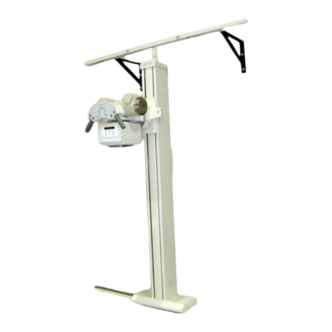
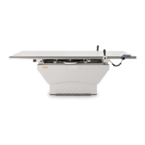
Table of Contents
HF Series X-ray Generators - Service Manual Revision W
Quantum Medical Imaging ix
CHAPTER 6 - DIAGRAMS (CONT’D)
Three-Phase (208-240) Input (32, 40 and 50 kW without High
Speed Starter) X-ray Generators Interconnection Diagram ...................6-26
Three-Phase (50, 65 and 80 kW with AID High Speed Starter) X-ray
Generators Interconnection Diagram ..................................................6-27
Three-Phase (32, 40 and 50 kW without High Speed Starter, with
Universal AEC Board) X-ray Generators Interconnection Diagram .........6-28
Three-Phase (65 and 80 kW with AID High Speed Starter, Universal
AEC Board) X-ray Generators Interconnection Diagram ........................6-29
Three-Phase (208-240) Input (32, 40 and 50 kW without High Speed Starter,
with Universal AEC Board) X-ray Generators Interconnection Diagram AEC6-30
Three-Phase (208-240) Input (50 kW with QMI High Speed Starter) X-ray Generator
Interconnection Diagram ....................................................................6-31
Three-Phase (208-240) Input (50 kW with QMI High Speed Starter and
Tomography Interface) X-ray Generator Interconnection Diagram ........6-32
Three-Phase (65 and 80 kW with QMI High Speed Starter) X-ray
Generator Interconnection Diagram ....................................................6-33
Three-Phase (65 and 80 kW with QMI High Speed Starter and Tomography
Interface) X-ray Generator Interconnection Diagram ...........................6-34
Operator Control Panel - ODYSSEY/QUEST Wiring Diagram ...................6-35
Q-Connect Option System Interconnection Diagram .............................6-36
Operator Control Panel Circuit Block Diagram (Non-Q-VISION OCP) .......6-37
Generator Logic Circuit Block Diagram .................................................6-38
Filament Regulator Control Circuit Block Diagram .................................6-39
KVP & Filament Control Circuit Block Diagram ......................................6-40
Single-Phase (Non-STORED ENERGY) and Three-Phase Line Monitor
Circuit Block Diagram ........................................................................6-41
Single-Phase STORED ENERGY Line Monitor Circuit Block Diagram ........6-42
Interface Board A9 (AY40-023T/AY40-023T1) Schematic Diagram .........6-43
Interface Board, Digital Receptor A9 (AY40-034T) Interface Diagram .....6-44
Interface Board, Digital Receptor A9 (AY40-061T) Interface Diagram .....6-45
Power Supply Board A6 (AY40-005T) Schematic Diagram 46
Rotor Circuit Block Diagram ................................................................6-47
QMI High-Speed Starter Circuit Block Diagram .....................................6-48
Logic Board A1 (AY40-006S) Test Point/Jumper Location Diagram .........6-49
KVP Control Board A2 (AY40-003S) Test Point/Jumper Location Diagram 6-50
Filament Control Board A5 (AY40-007T) - Test Point/Jumper Location
Diagram ...........................................................................................6-51
Power Supply Board A6 (AY40-005T) - Test Point/Jumper Location
Diagram ...........................................................................................6-52
Line Monitor Board A8 (AY40-022T1), Single-Phase Systems - Test
Point/Jumper Location Diagram .........................................................6-53
Line Monitor/Battery Charger Board A8 (AY40-028T), Stored-Energy
Systems - Test Point/Jumper Location Diagram ...................................6-54
Line Monitor Board A8 (AY40-022T2/T3), Three-Phase Systems - Test
Point/Jumper Location Diagram .........................................................6-55
Line Monitor Board A8 (AY40-053S2/AY40-053S3), Three-Phase QMI
High-Speed Starter Systems - Test Point/Jumper Location Diagram ......6-56

Table of Contents
Revision W HF Series X-ray Generators - Service Manual
xQuantum Medical Imaging
CHAPTER 6 - DIAGRAMS (CONT’D)
Interface Board (No HSS Non-Digital) A9 (AY40-023T) - Terminal
Block/Jumper Location Diagram ..........................................................6-57
Digital Interface Board (No HSS with Digital Receptor) A9 (AY40-034T) -
Terminal Block/Jumper Location Diagram ............................................6-58
Interface Board (HSS Non-Digital) A9 (AY40-061T) Terminal Block/Jumper
Location Diagram ..............................................................................6-59
Digital Interface Board (HSS with Digital Receptor) A9 (AY40-062T)
Terminal Block/Jumper Location Diagram ............................................6-60
Rotor Drive Board A10 (AY40-013T) - Terminal Block Location Diagram .6-61
Standard AEC Board A11 (AY40-031S) - Test Point/Jumper Location
Diagram ...........................................................................................6-62
Universal AEC Board A11 (AY40-027S) - Test Point/Jumper Location
Diagram ...........................................................................................6-63
OCP Control Board A16A1 (AY40-004S1) - Test Point/Jumper
Location Diagram ..............................................................................6-64
OCP Interface Board A1A1 (AY40-073S) - Test Point/Jumper Location
Diagram ...........................................................................................6-65
QMI High-Speed Starter Control Board A20A1 (AY40-035S) - Test
Point/Potentiometer Location Diagram ................................................6-66
QMI High-Speed Starter Driver Board A20A2 (AY40-036S) - Test
Point/Fuse Location Diagram ..............................................................6-67
APPENDIX A - AEC CALIBRATION WITH
DIGITAL RECEPTOR OR CR FILM PLATE
OVERVIEW .......................................................................................... A-3
SPECIAL CANON DR SYSTEM CONFIGURATION INSTRUCTIONS .......A-3
AEC CALIBRATION WITH DIGITAL RECEPTOR OR CR FILM PLATE
INSTALLED .................................................................................. A-4
AEC Calibration Instructions - One Ion Chamber Per Panel .........A-8
AEC Calibration Instructions - Single Panel, Dual Ion Chambers A-13
APPENDIX B - CALIBRATION (AGFA DIREX)
OVERVIEW .......................................................................................... B-3
REQUIRED TOOLS AND MATERIALS ............................................... B-4
SYSTEM CONFIGURATION/CALIBRATION ............................................. B-4
ACCESSING SERVICE MODE ........................................................... B-4
FACTORY RESET ........................................................................... B-8
Factory Reset .......................................................................... B-8
Backup Configuration Utility ...................................................... B-9
GENERATOR CONFIGURATION ..................................................... B-10
Generator Settings ................................................................. B-13
Tube Settings ........................................................................ B-15
Ion Chamber Configuration .................................................... B-17
Film/Screen Default Settings ................................................... B-21

Table of Contents
HF Series X-ray Generators - Service Manual Revision W
Quantum Medical Imaging xi
APPENDIX B - CALIBRATION (AGFA DIREX) (CONT’D)
Copy Film Screen Utility ..........................................................B-23
GENERATOR CALIBRATION ..........................................................B-25
General Calibration Procedure Notes ........................................B-26
A/D Calibration ......................................................................B-27
kV Calibration ........................................................................B-30
Filament Offset Calibration ......................................................B-32
MA Calibration ......................................................................B-37
AEC CALIBRATION .......................................................................B-40
Ion Chamber Balancing (Three-field Chambers) .......................B-43
AEC MAS Balance Verification ..................................................B-45
Film Screen Selection .............................................................B-47
The AEC Calibration Menu ......................................................B-50
Optical Density Calibration ......................................................B-51
AEC Optical Density Calibration ...............................................B-52
AEC KV Calibration Procedure .................................................B-55
APPENDIX C - LOG4VIEW ERROR LOGGER
APPENDIX D - (QG-DIG-CXDI CANON/QUANTUM
INTEGRATION) CALIBRATION
OVERVIEW ......................................................................................... D-3
REQUIRED TOOLS AND MATERIALS ............................................... D-4
ACCESSING GENERATOR SERVICE TOOLS ...................................... D-4
Accessing Generator Service Tools - Q-VISION Operator
Control Panel ......................................................................... D-5
Accessing Generator Service Tools - Workstation-Based
Operator Control Panel ........................................................... D-7
SYSTEM CONFIGURATION/CALIBRATION ............................................D-10
GENERATOR CONFIGURATION .....................................................D-12
Generator Settings Tab ...........................................................D-12
Generator Calibrations Tab .....................................................D-13
Tube Settings Tab ..................................................................D-13
Physical Receptors Tab ...........................................................D-15
Receptors Tab .......................................................................D-16
Ion Chambers Tab .................................................................D-18
Licensing Tab ........................................................................D-20
GENERATOR CALIBRATION ..........................................................D-21
A/D Tab ................................................................................D-24
kVp Calibration Tab ................................................................D-28
Filament Offset Calibration ......................................................D-31
MA Calibration Tab .................................................................D-41
AEC CALIBRATION .......................................................................D-45
Ion Chamber Balancing (Three-field Chambers) .......................D-47
AEC MAS Balance Verification ..................................................D-50
The AEC Calibration Tab .........................................................D-52

Table of Contents
Revision W HF Series X-ray Generators - Service Manual
xii Quantum Medical Imaging
APPENDIX D - (QG-DIG-CXDI CANON/QUANTUM
INTEGRATION) CALIBRATION (CONT’D)
Base OD Calibration Procedure ...............................................D-56
AEC kVp Calibration Procedure ...............................................D-58
Copy Receptor Calibration Tab ................................................D-62

Chapter
1-1
SPECIFICATIONS
1

1-2

Chapter 1 Specifications
HF Series X-ray Generators - Service Manual Revision W
Quantum Medical Imaging 1-3
SYSTEM CONFIGURATIONS
The tables below show model numbers of components in each type of HF SeriesTM
X-ray Generator system (hereinafter referred to as the "HF Series X-ray Generators").
Note: The X-Ray Control Models shown in the following
tables are not used if the HF generator system is integrated
with computed radiographic (CR) or digital radiographic (DR)
workstation computer (e.g., Agfa NX, Canon CXDI, etc.).
Single-Phase Model Generators
SYSTEM
TYPE CATALOG
NO. SYSTEM
MODEL
GENERATOR
CABINET
MODEL
X-RAY
CONTROL
MODEL*
ODYSSEY HF
32 kW QG-3200 QG-32 QG-32G QG-3200
ODYSSEY HF
32 kW QG-32-5 QG-32G-5 QG-3200
ODYSSEY HF
40 kW QG-4000 QG-40 QG-40G QG-4000
ODYSSEY HF
40 kW QG-40-5 QG-40G-5 QG-4000
Q-VISION HF
32 kW QGV-32 QG-32 QG-32G QGV-32
QGV-32-5 QG-32-5 QG-32G-5
Q-VISION HF
40 kW QGV-40 QG-40 QG-40G QGV-40
QGV-40-5 QG-40-5 QG-40G-5
Three-Phase Model Generators
SYSTEM
TYPE CATALOG
NO. SYSTEM
MODEL
GENERATOR
CABINET
MODEL
X-RAY
CONTROL
MODEL
ODYSSEY
HF 32 kW QG-3200 QG-32-2 QG-32G-2 QG-3200
QG-32-3 QG-32G-3
ODYSSEY
HF 40 kW QG-4000 QG-40-2 QG-40G-2 QG-4000
QG-40-3 QG-40G-3
ODYSSEY
HF 50 kW QG-5000 QG-50-2 QG-50G-2 QG-5000
QG-50 QG-50G

Chapter 1 Specifications
Revision W HF Series X-ray Generators - Service Manual
1-4 Quantum Medical Imaging
ODYSSEY
HF 65 kW QG-6500 QG-65 QG-65G QG-6500
ODYSSEY
HF 80 kW QG-8000 QG-80 QG-80G QG-8000
Q-VISION
HF 32 kW QGV-32-2 QG-32-2 QG-32G-2 QGV-32
QGV-32-3 QG-32-3 QG-32G-3
Q-VISION
HF 40 kW QGV-40-2 QG-40-2 QG-40G-2 QGV-40
QGV-40-3 QG-40-3 QG-40G-3
Q-VISION
HF 50 kW QGV-50-2 QG-50-2 QG-50G-2 QGV-50
QGV-50 QG-50 QG-50G
Q-VISION
HF 65 kW QGV-65 QG-65 QG-65G QGV-65
Q-VISION
HF 80 kW QGV-80 QG-80 QG-80G QGV-80
STORED ENERGY (SE) Model Generators
SYSTEM
TYPE CATALOG
NO. SYSTEM
MODEL
GENERATOR
CABINET
MODEL
X-RAY
CONTROL
MODEL
ODYSSEY
HF 32 kW QG-3200-SE QG-32-SE QG-32G-SE QG-3200
ODYSSEY
HF 40 kW QG-4000-SE QG-40-SE QG-40G-SE QG-4000
ODYSSEY
HF 50 kW QG-5000-SE QG-50-SE QG-50G-SE QG-5000
Q-VISION
HF 32 kW QGV-32-SE QG-32-SE QG-32G-SE QGV-32-SE
Q-VISION
HF 40 kW QGV-40-SE QG-40-SE QG-40G-SE QGV-40-SE
Q-VISION
HF 50 kW QGV-50-SE QG-50-SE QG-50G-SE QGV-50-SE
Three-Phase Model Generators
SYSTEM
TYPE CATALOG
NO. SYSTEM
MODEL
GENERATOR
CABINET
MODEL
X-RAY
CONTROL
MODEL

Chapter 1 Specifications
HF Series X-ray Generators - Service Manual Revision W
Quantum Medical Imaging 1-5
PHYSICAL SPECIFICATIONS
The following are physical specifications of the HF Series X-ray Generators:
GENERATOR CABINET SPECIFICATIONS
Width: 24.0 inches (609.6 mm)
Depth: 20.0 inches (508.0 mm)
Height: 34.7 inches (881.4 mm)
Weights:
Single-Phase (non-SE units): 298 lbs. (135.2 kg)
32, 40 and 50 kW Stored
Energy (SE) units: 431 lbs. (195.5 kg)
50, 65, 80 kW Three-Phase
units): 380 lbs. (712.4 kg) w/o internal HSS
388 lbs. (176.0 kg) w/internal HSS
OPERATOR CONTROL PANEL SPECIFICATIONS
Note: X-Ray Control Panels below are utilized with HF gener-
ator systems integrated with computed radiographic (CR) or
digital radiographic (DR) workstation computers (e.g., Agfa
NX, Canon CXDI, etc.).
The Q-VISION all-in-one operator control is not powered from the generator cab-
inet; it requires a separate 100-240 VAC, 3A power input.
ODYSSEY HF Control Panel:
Width: 17.9 inches (454.7 mm)
Depth: 12.25 inches (311.2 mm)
Height (without pedestal): 3.3 inches (83.8 mm)
Height (with pedestal): 36.5 inches (927.4 mm)
Weight (without pedestal): 5 lbs. (2.3 kg)
Weight (with pedestal): 25 lbs. (11.3 kg)
Q-VISION HF Control Panel:
Width: 18.7 inches (476.0 mm)
Depth (without stand): 1.9 inches (49.0 mm)
Depth (with stand): 7.125 inches (181.0 mm)
Height: 14.4 inches (365.0 mm)
Weight: 13 lbs. (5.9 kg)
SYSTEM SPECIFICATIONS
System Compatibility: Compatible with all Quantum Medical
Imaging tube stands, overhead tube
cranes, radiographic tables and wall stands
Tube Compatibility: Toshiba Models E7239X, E7242X, E7252X,
E7254X, E7255X, E7813X, E7869X
Varian Models RAD-8, RAD-13, RAD-14,
RAD-21, RAD-44, RAD-56, RAD-60,
RAD-68, RAD-74, RAD-92, A192, A272,
A292

Chapter 1 Specifications
Revision W HF Series X-ray Generators - Service Manual
1-6 Quantum Medical Imaging
Dunlee Models PX 1302, PX 1429, PX 1436,
PX 1312, DU 309, DA 1092, MX100
replacement tube for GE Radiographic
Systems
(For tube types not listed, consult factory.)
Collimators: Huestis Manual, Model 150MC
Huestis Automatic, Model 150PBL
Huestis Selectable, Model 150A,
Progeny Linear MC150 (Manual)
Progeny Linear II and Linear IV
(Automatic)
Note: The HF Series radiographic systems are compatible with any
automatic collimating system that provides an isolated nor-
mally open switch that closes when the Automatic Collima-
tion System presents an “EXPOSURE READY” mode to the
control; they are also compatible with any beam limiting
device that complies with 21 CFR Subchapter J intended for
radiographic equipment.
POWER REQUIREMENTS
In order to assure the proper operation of our equipment and subsequently, the produc-
tion of high-quality radiographs, it is essential that all power requirements, as specified in
the tables that follow, are suitably met by the facility in which the equipment is installed.
This includes usage of the proper size conductor between distribution transformer and dis-
connect switch, connection to a supply transformer of sufficient capacity (specified in
terms of KVA), insuring the AC input voltage tolerance meets specification (±5% or ±10%
depending on model), and voltage regulation of 5% at full load is maintained. All wiring
and grounding at the installation site must be in accordance with applicable National Elec-
tric Code (NEC) and/or local electrical codes.
THe generator requires a 3-phase "Y" connection, measured line-to-line, balanced to
earth or neutral. The "Y" connection can be 4-wire (L1, L2, L3, Neutral) and GND or
3-wire (L1, L2, L3) and GND. The 4-wire connection may be required by local electri-
cal code and in connection where a roughly balanced 3-phase source exists (e.g.,
when using a delta-to-Y transformer).
Note that failure to comply with the above requirements not only may result in
improper generator operation and/or performance, but it will also void the warranty,
as the warranty is exclusive of the following conditions:
• "Failure of customer to prepare the site or provide power requirements or
operating environmental conditions in compliance with any applicable
instructions or recommendations of QMI.
• "Failure of customer to provide the proper incoming power required to support
the equipment in accordance with the recommendation of QMI.
• "Improper or extraordinary use of the Product, improper maintenance of the
Product, or failure to comply with any applicable instructions or
recommendations of Quantum Medical Imaging, LLC.
This manual suits for next models
24
Table of contents
Other Quantum Medical Equipment manuals

Quantum
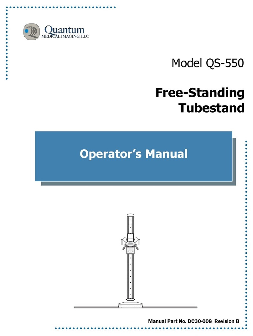
Quantum QS-550 User manual

Quantum
Quantum QS-550 User manual

Quantum
Quantum QT-740 User manual

Quantum
Quantum QT-740 User manual

Quantum
Quantum QT-740 User manual

Quantum
Quantum QS-500 Series User manual

Quantum
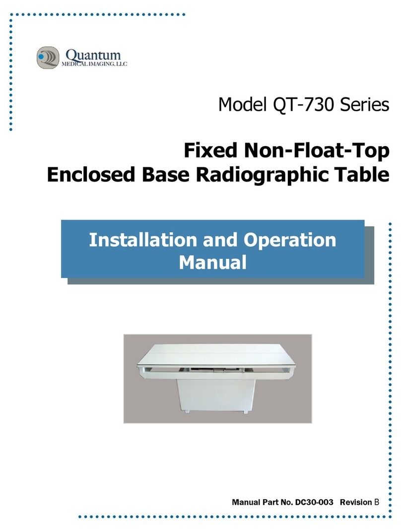
Quantum QT-730 Series User manual

Quantum
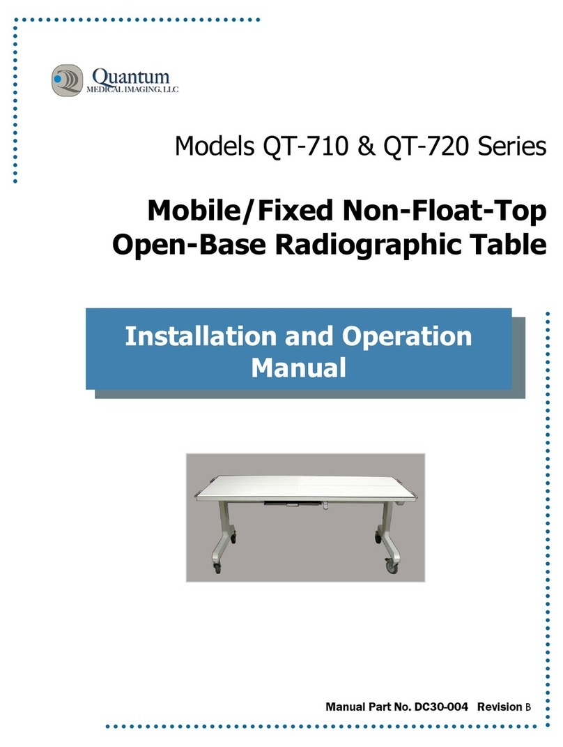
Quantum QT-710 User manual

Quantum
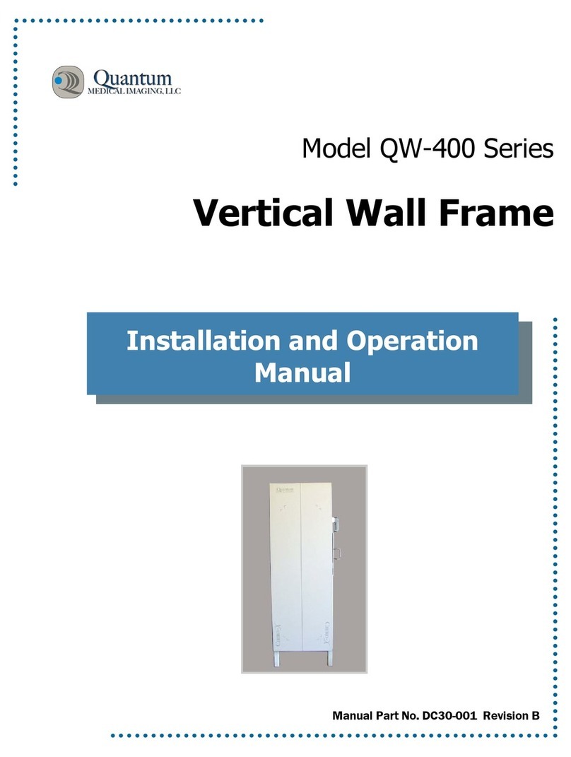
Quantum QW-400 Series User manual