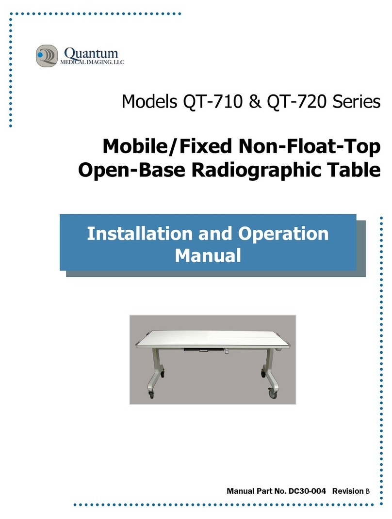
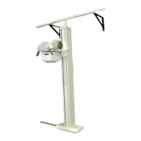
Quantum QS-550 User manual

Model QS-550
Free-Standing
Tubestand
Service Manual
Manual Part No. DC30-009 Revision B

Copyright © 2001 QMI
This manual is copyrighted and all rights are reserved. No portion of this document
may be copied, photocopied, reproduced, translated, or reduced to any electronic
medium or machine readable form without prior consent in writing from Quantum
Medical Imaging, LLC.
Made in U.S.A.
Quantum Medical Imaging, LLC
2905 Veterans Memorial Highway
Ronkonkoma, New York 11779 USA
Phone: (631) 567-5800
Fax: (631) 567-5074

Revision History
Model QS-550 - Service Manual i
REVISION DATE TYPE OF MODIFICATION
A 12/7/00 Initial Release.
B 2/28/01 Minor modification made to installation of tube
stand on floor track procedure.
Page
Number Rev
Page
Number Rev
Page
Number Rev
i - x B
1 - 47 B

Revision History
ii Model QS-550 - Service Manual
THIS PAGE INTENTIONALLY LEFT BLANK

Table of Contents
Model QS-550 - Service Manual iii
Table of Contents
Chapter 1, Specifications 1
Chapter 2, Assembly and Installation 7
Chapter 3, Theory of Operation 27
Chapter 4, Service Maintenance 33
Chapter 5, Diagrams 41

Table of Contents
iv Model QS-550 - Service Manual
THIS PAGE INTENTIONALLY LEFT BLANK

Chapter
1
1
SPECIFICATIONS

2

Chapter 1 Specifications
Model QS-550 - Service Manual 3
PHYSICAL SPECIFICATIONS
SYSTEM SPECIFICATIONS
• Column Height: 92.0 inches (2336.8 mm)
• Tube Mount: Fork or Trunnion
• Weight: 600 lbs. (272.0 kg)
• Collimator
Compatibility: Manual, Selectable or Automatic, 10 - 20 lbs. (typi-
cal). Mounting to fork/tube housing requires four
1/4-20 or M6 x 16 bolts spaced on a 3.625" diame-
ter circle
•X-rayTube
Compatibility: 3" or 4" rotating anode type, 30 - 40 lbs. (typical)
HANDGRIP SPECIFICATIONS
• Controls: Switches (Vertical, Longitudinal, Angulation,Trans-
verse, All Locks), Auto-Stop
• LED Indicators: 40” (100 cm) SID, 72” (180 cm) SID
• LCD Display: 40 inches (100 cm) and 72 inches (180 cm) SID,
tube rotation angle, time, date, x-ray generator
technique selection when APR mode is activated (or
mode [i.e., AEC/Manual] when not in APR mode)
PERFORMANCE SPECIFICATIONS
• Tubestand
Longitudinal Travel: 96.0 inches (1752.6 mm)
• Vertical Travel (x-ray
tube): 60.0 inches (1524.0 mm)
•X-rayTubeHeight:
Maximum: 72.5 inches (1848.2 mm)
Minimum: 13.0 inches (330.2 mm)
• Transverse Tube
Travel: ±5 inches (127 mm) from centerline of table
• Transverse Travel
Detent: Center position
•X-rayTube
Angulation: 240° (±120°)
• X-ray Tube Angulation
Detents: 0°, 90°(CW), 90°(CCW)
• Column Rotation: 180° (±90°)
• Column Rotation
Detents: 0°, 90°(L), 90°(R)

Chapter 1 Specifications
4Model QS-550 - Service Manual
ELECTRICAL SPECIFICATIONS
Note: The following specifications are for the tubestand only and do not
apply to the x-ray tube or collimator. Refer to x-ray tube and collimator
manufacturer’s documentation (supplied with the tubestand) for
applicable specifications.
•LockingSystem
Power: +24 VDC, 1.0 Ampere
• Mode of Operation: Continuous
• Power Supply Type: Double (or Reinforced) Insulated (must meet con-
struction/performance criteria per UL 2601-1)
• Electrical Interfacing: Tubestand-mounted terminal strip for interfacing
+24 VDC and, when equipped with automatic colli-
mator, tray sensing signals
SYSTEM OPTIONS
• Six-Button non-LCD type Handgrip
• Fork Mount (replaces Trunnion Mount)
• Floor Grout Kit
SYSTEM OPERATING ENVIRONMENT
Note: The tubestand is not designed for use in the presence of explosive
or flammable gases as might be found in operating rooms.
•Ambient
Temperature: +10°C to +40°C
• Relative Humidity: 20 to 80%, non-condensing
• Altitude: -30.5 to +2440 meters relative to sea level
NON-OPERATING ENVIRONMENT
Note: Operation or prolonged storage temperatures below 32 degrees
Fahrenheit should be avoided as it will cause lubricants to become more
resistive to manually-operated motions.
•Ambient
Temperature: -18°C to +70°C
• Relative Humidity: 20 to 95%, non-condensing
• Altitude: -30.5 to +3048 meters relative to sea level
COMPATIBILITY STATEMENT
The Quantum Medical Imaging, LLC. tubestand is compatible with all Quantum Medi-
cal Imaging, LLC. manufactured tables, wall stands, and high-voltage x-ray genera-
tors, and with other manufacturer’s equipment having equivalent means for indication
of SID and perpendicularity.
Chapter 1 Specifications
Model QS-550 - Service Manual 5
Figure 1. Model QS-550 Tubestand Configuration Diagram

Chapter 1 Specifications
6Model QS-550 - Service Manual
THIS PAGE INTENTIONALLY LEFT BLANK

Chapter
7
2
ASSEMBLY &
INSTALLATION

8

Chapter 2 Assembly & Installation
Model QS-550 - Service Manual 9
OVERVIEW
This chapter describes the steps required to assemble and install the Model QS-550
Tubestand, including making all required electrical connections, and performing all
required alignments and calibrations.
ROOM CONSTRUCTION
A conventional radiographic room construction should be used in the area where
the tubestand is to be installed. Consult with your State Health Department or
local Building Codes for specific radiation shielding requirements.
INSTALLATION PRECAUTIONS
Install the tubestand before installing the radiographic table.
Check that the space location, conduit arrangements and junction boxes are pre-
pared for the permanent installation of the tubestand. Verify that the location
and space allowed is sufficient for the full range of tubestand/Transverse Arm
travel without hitting any walls or structures in the room (see Figure 1 for equip-
ment dimensions). Note that the Transverse Arm in/out adjustment and the Ver-
tical Column position relative to the rear wall are critical. Column rotation in the
counterclockwise (right-hand) direction could result in the Tube Housing striking
the wall before the 90 degree index position is reached.
CDRH CERTIFICATION
The tubestand is not a CDRH certifiable product. However, it must be compatible
and operate in conjunction with other components in the x-ray system so that the
x-ray system performs in compliance with CDRH performance standards.
REQUIRED TOOLS AND MATERIALS
The following tools and materials are required to complete the assembly and
installation procedures:
• Double-bubble level - two feet minimum length
• Tape Measure - eight feet minimum length
• Standard hand tools
• Alcohol - to clean the high-tension cable ends, tubehead, and high- tension
transformer sockets
• Dow-Corning DC4 vapor-proofing compound, silicon insulating grease or
equivalent - for packing x-ray tubehead and high-tension cable terminals
• Special film cassette (11" x 14" cassette with scribed centerline)
• Electric drill and drill bits
• Lubricant - white lithium grease

Chapter 2 Assembly & Installation
10 Model QS-550 - Service Manual
UNPACKING
Open crate or carton marked "packing list enclosed" first. Remove packing list
and use it as a guide to open the remaining cartons. Do not dispose of packing
material until packing list is matched with actual parts received. Should there be
a shortage or damage, notify Quantum Medical Imaging, LLC.’s customer service
department immediately. The manufacturer is relieved of any responsibility for
damage during shipment after unit is picked up by the carrier.
INSTALLATION INSTRUCTIONS
When the Tubestand is used with a vertical wall frame or wall stand, care should
be taken during room planning and pre-installation to allow for the accurate align-
ment of these components. Alignment accuracy must be within 2% of the SID
used. After the tubestand Floor Track is aligned with the table receptor, the track
cannot be adjusted transversely. Therefore, transverse alignment of the x-ray
field to the image receptor in the vertical wall frame or wall stand must be made
by adjusting the position of the image receptor within the wall stand or relocation
of the entire wall stand.
All mounting procedures must be approved before and checked after installation
by the hospital or facility engineering department and a registered, professional,
structural engineer. It is recommended that a leakage current measurement be
taken following installation to verify system meets allowable levels.
To assemble and install the tubestand, refer to Figures 2 through 20 and proceed
as follows:
Floor Track Installation
The area of the floor on which the Floor Track is to be mounted must be
level in all directions. Shims may be used, however, grouting is recom-
mended.
1. Position the Floor Track in the proper location for installation.
2. Using a bubble-level, check that the Floor Track is level both lon-
gitudinally and transversely. If not, shims can be used to level
track, however, grout is recommended.
3. Fasten the Floor Track to the floor using appropriate fastening
hardware (capable of supporting 100 lb. pull-load) depending on
the installation site (see Figure 2).
4. Install five (5) Hole Plugs in holes for floor mounting screws.
Vertical Column/Base Assembly Attachment
Mount the Base Assembly to the Vertical Column and secure with the
supplied retaining ring at the bottom of Vertical Column (see Figure 3).
NOTE
Examine all car-
tons and crates
carefully at time
of delivery. If
damage is appar-
ent, have deliv-
ery driv er write a
"Dam ag ed Ship-
ment Note" on
copies of fr eight
bill, sign it, and
file appropri ate
carrier claim.
Should you dis-
cover concealed
damage, immedi-
ately no tify the
transporting
agent and ask
for an
"Inspection of
Damage". Carrier
will not accept
concealed dam-
age claim if filed
after 15 days
from date of
receipt of mer-
chandise.

Chapter 2 Assembly & Installation
Model QS-550 - Service Manual 11
Figure 2. Floor Track Installation
MOUNTING
HOLES (5X)
Figure 3. Installing the Column Retaining Ring
RETAINING
RING

Chapter 2 Assembly & Installation
12 Model QS-550 - Service Manual
INSTALLING TUBESTAND ON FLOOR TRACK
1. Remove the End Cap from one end of the Floor Track.
2. At the end of Floor Track without End Cap, slide the Front and Rear Bearing
Bracket Assemblies into the Floor Track.
3. Raise the Base and Vertical Column onto the Floor Track.
4. Securel the Front and Rear Bearing Brackets to the Base Assembly (see Fig-
ures 4 and 5).
Figure 4. Bearing Bracket Locations
FRONT
BEARING
BRACKET
BEARING W/
ECCENTRIC
BUSHING
REAR
BEARING
Figure 5. Vertical Column Angle Adjustment

Chapter 2 Assembly & Installation
Model QS-550 - Service Manual 13
CAUTION! When Bearing Brackets are removed,
extreme care must be taken not to tip over the
Base Assembly and Vertical Column. The Base
Assembly and Vertical Column should not be left
standing unattended at any time. Re-install Front
and Rear Bearing Brackets immediately once the
column is raised.
5. Re-install the End Cap to the end of the Floor Track using four (4) 5/16-18 x
1/2" hex head bolts, lockwashers and flat washers.
6. Using a two-foot (minimum) double-bubble level, placed on the front of the
Vertical Column, check that the Vertical Column is plumb. If not, adjustment
can be made by rotating the two (2) Vertical Angle Adjustment Bearings with
eccentric bushings (see Figure 5). Loosen the two (2) eccentric bearings
mounted to the rear of the Base Assembly; rotate the bearings to adjust. Re-
tighten the bearings after the column angle adjustment is made.
INSTALLING THE TRANSVERSE ARM
1. Align mounting holes in the Transverse Arm with holes in Vertical Column
Trolley and install four (4) 3/8-16 x 1-1/2" hex head bolts and lockwashers
(see Figure 6).
Figure 6. Installing the Transverse Arm
LEVELING SET
SCREW (4X)
3/8-16 X 1-1/2"
HEX HEAD
BOLT (4X)

Chapter 2 Assembly & Installation
14 Model QS-550 - Service Manual
2. Place a level on top or bottom of the Transverse Arm (from front to back). If
not level (±1.0°), verify the Floor Track and Vertical Column are level.
3. If both Floor Track and Transverse Arm are level, loosen four (4) 1/4-20 x 1-
1/2" hex head bolts securing Transverse Arm to Trolley.
4. Adjust four (4) set screws as required to level Transverse Arm (see Figure 6).
5. Re-tighten four (4) 1/4-20 x 1-1/2" hex head bolts.
INSTALLING THE X-RAY TUBE, COLLIMATOR AND HANDGRIPS
CAUTION! The tube angulation lock is not a
mechanical lock; electrical power must be applied
to hold angulation. During installation, the x-ray
tube and collimator must be held to prevent free-
turning. Mount the collimator per instructions
supplied by the collimator manufacturer.
The system is supplied with either a Trunnion type x-ray tube mounting bracket
or a Tube Mounting Fork. Refer to the appropriate paragraph that follows corre-
sponding with the type of x-ray tube mounting bracket used on your system.
Trunnion Configuration
1. Install the Trunnion Assembly onto the Transverse Arm using four
(4) 1/4-20 x 2" hex head bolts and lockwashers (see Figure 7).
1/4-20 X 2" HEX
HEAD BOLT
AND LOCK-
WASHER (4X)
TUBE SUPPORT
BRACKET
COLLIMATOR
MOUNTING
PLATE
Figure 7. Mounting the Tube and Trunnion Assembly
TRUNNION
ASSEMBLY
Other manuals for QS-550
1
Table of contents
Other Quantum Medical Equipment manuals

Quantum
Quantum QS-500 Series User manual

Quantum
Quantum QT-740 User manual

Quantum
Quantum QS-550 User manual

Quantum
Quantum QT-730 Series User manual

Quantum
Quantum QT-740 User manual

Quantum
Quantum QT-710 User manual

Quantum
Quantum QT-740 User manual

Quantum
Quantum ODYSSEY HF Series User manual

Quantum
Quantum QW-400 Series User manual
Popular Medical Equipment manuals by other brands

Getinge
Getinge Arjohuntleigh Nimbus 3 Professional Instructions for use

Mettler Electronics
Mettler Electronics Sonicator 730 Maintenance manual

Pressalit Care
Pressalit Care R1100 Mounting instruction

Denas MS
Denas MS DENAS-T operating manual

bort medical
bort medical ActiveColor quick guide

AccuVein
AccuVein AV400 user manual