Quantum QT-740 User manual

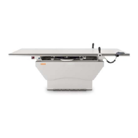
Models QT-740 and QT-750
Manual Part No. DC30-007 Revision B
Service Manual
Fixed/Elevating
Float-Top
Radiographic Tables

Copyright© 2000 QMI
This manual is copyrighted and all rights are reserved. No portion of this document
may be copied, photocopied, reproduced, translated, or reduced to any electronic
medium or machine readable form without prior consent in writing from Quantum
Medical Imaging, LLC.
Made in U.S.A.
Quantum Medical Imaging, LLC
2905 Veterans Memorial Highway
Ronkonkoma, New York 11779 USA
Phone: (631) 567-5800
Fax: (631) 567-5074

Revision History
Models QT-740 & QT-750 - Service Manual i
REVISION DATE TYPE OF MODIFICATION
A 12/07/00 Initial Release.
B 1/5/01 Added long. magnet adjustment, tabletop width
adjustment, DC Motor Driver Bd. replacement procedure
Page
Number Rev
Page
Number Rev
Page
Number Rev
i - iv B
1 - 57 B

Revision History
ii Models QT-740 & QT-750 - Service Manual
THIS PAGE INTENTIONALLY LEFT BLANK

Table of Contents
Models QT-740 & QT-750 - Service Manual iii
Chapter 1 Specifications
PHYSICAL SPECIFICATIONS . . . . . . . . . . . . . . . . . . . . . . . . . . . . . . . . . . . . . . . . . . . . . . . . . . . . . . . . . . 3
TABLETOP SPECIFICATIONS . . . . . . . . . . . . . . . . . . . . . . . . . . . . . . . . . . . . . . . . . . . . . . . . . . . . . . . 3
TABLE BASE SPECIFICATIONS. . . . . . . . . . . . . . . . . . . . . . . . . . . . . . . . . . . . . . . . . . . . . . . . . . . . . . 3
IMAGE RECEPTOR SPECIFICATIONS . . . . . . . . . . . . . . . . . . . . . . . . . . . . . . . . . . . . . . . . . . . . . . . 3
SYSTEM SPECIFICATIONS . . . . . . . . . . . . . . . . . . . . . . . . . . . . . . . . . . . . . . . . . . . . . . . . . . . . . . . . . . 3
ELECTRICAL SPECIFICATIONS . . . . . . . . . . . . . . . . . . . . . . . . . . . . . . . . . . . . . . . . . . . . . . . . . . . . . . . 4
SYSTEM OPTIONS . . . . . . . . . . . . . . . . . . . . . . . . . . . . . . . . . . . . . . . . . . . . . . . . . . . . . . . . . . . . . . . . . . . . 4
SYSTEM OPERATING ENVIRONMENT . . . . . . . . . . . . . . . . . . . . . . . . . . . . . . . . . . . . . . . . . . . . . . . . . 4
NON-OPERATING ENVIRONMENT. . . . . . . . . . . . . . . . . . . . . . . . . . . . . . . . . . . . . . . . . . . . . . . . . . . . . 4
Chapter 2 Assembly & Installation
OVERVIEW. . . . . . . . . . . . . . . . . . . . . . . . . . . . . . . . . . . . . . . . . . . . . . . . . . . . . . . . . . . . . . . . . . . . . . . . . . . .9
UNPACKING. . . . . . . . . . . . . . . . . . . . . . . . . . . . . . . . . . . . . . . . . . . . . . . . . . . . . . . . . . . . . . . . . . . . . . . . . . 9
TABLE ASSEMBLY. . . . . . . . . . . . . . . . . . . . . . . . . . . . . . . . . . . . . . . . . . . . . . . . . . . . . . . . . . . . . . . . . . . . 9
POSITIONING THE TABLE BASE . . . . . . . . . . . . . . . . . . . . . . . . . . . . . . . . . . . . . . . . . . . . . . . . . . . . 9
ELECTRICAL CONNECTIONS . . . . . . . . . . . . . . . . . . . . . . . . . . . . . . . . . . . . . . . . . . . . . . . . . . . . . . 10
Power Input Connections (Permanent Wiring Configuration) . . . . . . . . . . . . . . . . . . . . . . . . . . 10
Bucky Power Input Connections . . . . . . . . . . . . . . . . . . . . . . . . . . . . . . . . . . . . . . . . . . . . . . . . . . 10
PBL Interlock Cable Connections . . . . . . . . . . . . . . . . . . . . . . . . . . . . . . . . . . . . . . . . . . . . . . . . . 10
ALIGNMENT PROCEDURES . . . . . . . . . . . . . . . . . . . . . . . . . . . . . . . . . . . . . . . . . . . . . . . . . . . . . . . . . . 12
TABLE LEVELING. . . . . . . . . . . . . . . . . . . . . . . . . . . . . . . . . . . . . . . . . . . . . . . . . . . . . . . . . . . . . . . . . 12
IMAGE RECEPTOR/COLLIMATOR X-RAY ALIGNMENT . . . . . . . . . . . . . . . . . . . . . . . . . . . . . 12
TABLETOP ASSEMBLY/INSTALLATION . . . . . . . . . . . . . . . . . . . . . . . . . . . . . . . . . . . . . . . . . . . . 14
OPERATIONAL CHECKS AND ADJUSTMENTS . . . . . . . . . . . . . . . . . . . . . . . . . . . . . . . . . . . . . . . . . 17
CHECKING TABLE FLOAT-TOP OPERATION . . . . . . . . . . . . . . . . . . . . . . . . . . . . . . . . . . . . . . . 17
CHECKING UP/DOWN OPERATION (MODEL QT-750 ONLY) . . . . . . . . . . . . . . . . . . . . . . . . . . 17
TABLE UP/DOWN SPEED ADJUSTMENT (MODEL QT-750 ONLY). . . . . . . . . . . . . . . . . . . . . . 18
PEDAL DISABLE SWITCH OPERATIONAL CHECK. . . . . . . . . . . . . . . . . . . . . . . . . . . . . . . . . . . 18
CHECKING THE OBSTRUCTION SENSORS (ELEVATING TABLE ONLY) . . . . . . . . . . . . . . 19
POSITIVE BEAM LIMITATION (PBL) COLLIMATORS . . . . . . . . . . . . . . . . . . . . . . . . . . . . . . . . 20
MODEL QT-750 COVERS INSTALLATION/ADJUSTMENT PROCEDURE . . . . . . . . . . . . . . . . . . 20

Table of Contents
iv Models QT-740 & QT-750 - Service Manual
Chapter 3 Theory of Operation
OVERVIEW . . . . . . . . . . . . . . . . . . . . . . . . . . . . . . . . . . . . . . . . . . . . . . . . . . . . . . . . . . . . . . . . . . . . . . . . . . 25
MODEL QT-740 TABLE . . . . . . . . . . . . . . . . . . . . . . . . . . . . . . . . . . . . . . . . . . . . . . . . . . . . . . . . . . . . . 25
Power Distribution . . . . . . . . . . . . . . . . . . . . . . . . . . . . . . . . . . . . . . . . . . . . . . . . . . . . . . . . . . . . . . 25
Float Control. . . . . . . . . . . . . . . . . . . . . . . . . . . . . . . . . . . . . . . . . . . . . . . . . . . . . . . . . . . . . . . . . . . 25
Foot Pedal Disable Circuit. . . . . . . . . . . . . . . . . . . . . . . . . . . . . . . . . . . . . . . . . . . . . . . . . . . . . . . . 26
Receptor Cabinet Lock . . . . . . . . . . . . . . . . . . . . . . . . . . . . . . . . . . . . . . . . . . . . . . . . . . . . . . . . . . 26
MODEL QT-750 TABLE . . . . . . . . . . . . . . . . . . . . . . . . . . . . . . . . . . . . . . . . . . . . . . . . . . . . . . . . . . . . . 26
Power Distribution . . . . . . . . . . . . . . . . . . . . . . . . . . . . . . . . . . . . . . . . . . . . . . . . . . . . . . . . . . . . . . 26
Voltage Regulation . . . . . . . . . . . . . . . . . . . . . . . . . . . . . . . . . . . . . . . . . . . . . . . . . . . . . . . . . . . . . . 26
Table Up Motion Control . . . . . . . . . . . . . . . . . . . . . . . . . . . . . . . . . . . . . . . . . . . . . . . . . . . . . . . . 27
Table Down Motion Control . . . . . . . . . . . . . . . . . . . . . . . . . . . . . . . . . . . . . . . . . . . . . . . . . . . . . . 28
Float Control. . . . . . . . . . . . . . . . . . . . . . . . . . . . . . . . . . . . . . . . . . . . . . . . . . . . . . . . . . . . . . . . . . . 30
Foot Pedal Disable Switch . . . . . . . . . . . . . . . . . . . . . . . . . . . . . . . . . . . . . . . . . . . . . . . . . . . . . . . . 30
Positive Beam Limitation. . . . . . . . . . . . . . . . . . . . . . . . . . . . . . . . . . . . . . . . . . . . . . . . . . . . . . . . . 30
Receptor Cabinet Lock . . . . . . . . . . . . . . . . . . . . . . . . . . . . . . . . . . . . . . . . . . . . . . . . . . . . . . . . . . 31
Emergency Stop Switch . . . . . . . . . . . . . . . . . . . . . . . . . . . . . . . . . . . . . . . . . . . . . . . . . . . . . . . . . . 31
Chapter 4 Service Instructions
OVERVIEW . . . . . . . . . . . . . . . . . . . . . . . . . . . . . . . . . . . . . . . . . . . . . . . . . . . . . . . . . . . . . . . . . . . . . . . . . . 35
SERVICE MAINTENANCE . . . . . . . . . . . . . . . . . . . . . . . . . . . . . . . . . . . . . . . . . . . . . . . . . . . . . . . . . . 36
Visual Inspection . . . . . . . . . . . . . . . . . . . . . . . . . . . . . . . . . . . . . . . . . . . . . . . . . . . . . . . . . . . . . . . 36
Functional Check for Model QT-750 Elevating Tables . . . . . . . . . . . . . . . . . . . . . . . . . . . . . . . . 36
Lubrication . . . . . . . . . . . . . . . . . . . . . . . . . . . . . . . . . . . . . . . . . . . . . . . . . . . . . . . . . . . . . . . . . . . . 38
REMOVAL/REPLACEMENT PROCEDURES . . . . . . . . . . . . . . . . . . . . . . . . . . . . . . . . . . . . . . . . . . 38
Replacing the Drive Belt (Model QT-750 Tables Only) . . . . . . . . . . . . . . . . . . . . . . . . . . . . . . . . 38
Replacing the Sync Belt (Model QT-750 Tables Only) . . . . . . . . . . . . . . . . . . . . . . . . . . . . . . . . . 39
Replacing the DC Motor (Model QT-750 Tables Only) . . . . . . . . . . . . . . . . . . . . . . . . . . . . . . . . 42
Replacing the DC Motor Driver Board A2 (Model QT-750 Tables Only) . . . . . . . . . . . . . . . . . 42
Receptor Cabinet Removal/Replacement . . . . . . . . . . . . . . . . . . . . . . . . . . . . . . . . . . . . . . . . . . . 44
Cassette Tray Removal Procedure . . . . . . . . . . . . . . . . . . . . . . . . . . . . . . . . . . . . . . . . . . . . . . . . . 45
REPLACEMENT PARTS AND ORDERING INFORMATION . . . . . . . . . . . . . . . . . . . . . . . . . . . . 45
ORDERING INFORMATION . . . . . . . . . . . . . . . . . . . . . . . . . . . . . . . . . . . . . . . . . . . . . . . . . . . . . . . . 46
Chapter 5 Diagrams
MODEL QT-740 RADIOGRAPHIC TABLE WIRING DIAGRAM. . . . . . . . . . . . . . . . . . . . . . . . . . . . 53
MODEL QT-750 RADIOGRAPHIC TABLE WIRING DIAGRAM. . . . . . . . . . . . . . . . . . . . . . . . . . . . 54
4-WAY TABLE CONTROL BOARD A1 (AY40-017T) . . . . . . . . . . . . . . . . . . . . . . . . . . . . . . . . . . . . . . 55
6-WAY TABLE CONTROL BOARD A1 (AY40-002T) . . . . . . . . . . . . . . . . . . . . . . . . . . . . . . . . . . . . . . 56
Chapter
1
1
SPECIFICATIONS

2

Chapter 1 Specifications
Models QT-740 & QT-750 - Service Manual 3
PHYSICAL SPECIFICATIONS
The following are physical specifications of the radiographic tables:
TABLETOP SPECIFICATIONS
Length: 85.0 inches (2159.0 mm)
Width:35.5inches (901.7mm)
Height (Model QT-740): 32.5 inches (825.5 mm)
Height (Model QT-750):
Raised: 32.5 inches (825.5 mm)
Lowered: 21.0 inches (533.4 mm)
Tabletop Travel:
Longitudinal: 32 inches (812.8 mm)
Lateral: 10 inches (254 mm)
Tabletop Motion: 4-Way Floating
Tabletop Material: Fiber-resin (phenolic)
Tabletop X-ray Density: <1.0 mm Aluminum
Tabletop-to-Film Plane
Distance: approx. 2.5 inches (63.5 mm)
TABLE BASE SPECIFICATIONS
Width: 48.0 inches (1219.2 mm)
Depth: 26.0 inches (660.4 mm)
Weight Capacity (Max. Patient
Load): 650 lbs. (295 kg)
IMAGE RECEPTOR SPECIFICATIONS
Compatible With: Grid Cabinet, Bucky, ACL Bucky
Receptor Longitudinal Travel: 20.0 inches (508.0 mm)
SYSTEM SPECIFICATIONS
Tube Stand Compatibility: Compatible with all Quantum Medical Imaging
tube stands and overhead tube cranes
Overall Weight:
Model QT-740: 350.0 lbs. (158.8 kg)
Model QT-750: 500.0 lbs. (226.8 kg)

Chapter 1 Specifications
4Models QT-740 & QT-750 - Service Manual
ELECTRICAL SPECIFICATIONS
Input Power: 115 VAC (±10%), 15 Amps, 50/60 Hz
230 VAC (±10%), 10 Amps, 50/60 Hz
Mode of Operation:
Model QT-740: Continuous
Model QT-750: Intermittent Operation (80 cycles/hour max.)
Momentary Current:
Model QT-740:2.0Amps
Model QT-750:5.0 Amps
Long Term Current:
Model QT-740: 0.05 Amps
Model QT-750: 0.20 Amps
Locking System Power: 24 VDC/4.35 Amp
SYSTEM OPTIONS
• Abdominal compression band
• Lateral cassette holder (for cross-table work)
SYSTEM OPERATING ENVIRONMENT
Ambient Temperature: +10°C to +40°C
Relative Humidity: 20 to 80%, non-condensing
Altitude: -30.5 to +2440 meters relative to sea level
NON-OPERATING ENVIRONMENT
Ambient Temperature: -18°C to +70°C
Relative Humidity: 20 to 95%, non-condensing
Altitude: -30.5 to +3048 meters relative to sea level

Chapter 1 Specifications
Models QT-740 & QT-750 - Service Manual 5
Figure 1. Model QT-740 Table Configuration Diagram

Chapter 1 Specifications
6Models QT-740 & QT-750 - Service Manual
Figure 2. Model QT-750 Table Configuration Diagram

Chapter
7
2
ASSEMBLY &
INSTALLATION

8

Chapter 2 Assembly & Installation
Models QT-740 & QT-750 - Service Manual 9
OVERVIEW
Preparing the table for operation requires completion of the following tasks:
• Positioning the Table Base
• Making the Electrical Connections
• Alignment Procedures
• Tabletop Assembly/Installation
• Checking Table Operation
• Installing the Covers
UNPACKING
Open crate or carton marked "packing list enclosed" first. Remove packing list and
use it as a guide to open the remaining cartons. Do not dispose of packing material
until packing list is matched with actual parts received. Should there be a shortage or
damage, notify Quantum Medical Imaging, LLC.’s customer service department imme-
diately. The manufacturer is relieved of any responsibility for damage during ship-
ment after unit is picked up by the carrier.
TABLE ASSEMBLY
The radiographic table is shipped with most of its major components assembled.
However, the tabletop assembly must be attached to the base assembly. After the
table is assembled, an operational check is performed. (This check is required only
on Model QT-750 Odyssey HF Series X-ray Generators.)
POSITIONING THE TABLE BASE
Place the table base in the approximate location where it will be mounted.
Ensure that the floor below the table is level. When positioning the table base,
ensure there is a minimum clearance of 87 inches from the outer edge of Bearing
Rail to the wall on either side of the table (see Figures 1 and 2). This allows for
installation of the tabletop rails following table mounting. If enough clearance is
provided, proceed to the "Electrical Connections" paragraph in this chapter.
If there is not enough clearance on either side to install the tabletop after the
table is mounted to the floor, the tabletop must be installed prior to mounting the
table. To install the tabletop, proceed to the paragraph entitled "Tabletop Assem-
bly/Installation" before performing the next procedure.
NOTE
Examine all car-
tons and crates
carefully at time
of delivery. If
damage is appar-
ent, have deliv-
ery driv er write a
"Dam aged Ship-
ment Note" on
copies of freight
bill, sign it, and
file appropri ate
carrier cl aim.
Should you dis-
cover conceal ed
damage, immedi-
ately no tify the
transporting
agent and ask
for an
"Inspection of
Damage". Carrier
will not accept
concealed dam-
age claim if filed
after 15 days
from date of
receipt of mer-
chandise.

Chapter 2 Assembly & Installation
10 Models QT-740 & QT-750 - Service Manual
ELECTRICAL CONNECTIONS
CAUTION! This equipment contains electrostatic
sensitive devices. Observe proper grounding pre-
cautions before handling components or printed
circuit boards.
The table can be powered from independently fused power source (mains) or
from specified equipment, such as an X-ray generator. The power supply line
input connection is fused internal to the table (2A for 115 VAC line input, 1A for
230 VAC line input for Model QT-740 tables; 6A for 115 VAC line input, 3A for 230
VAC line input for Model QT-750 tables).
For 115 VAC installations, a 25-foot power cord with a hospital-grade plug is fac-
tory pre-wired to the table. Based on installation requirements, the plug can be
removed, such as when the table is permanently wired to mains or an X-ray gen-
erator. For 230 VAC installations, a 25-foot "HAR" power cord is factory pre-wired
to the table. All electrical connections must be made in compliance with NEC
requirements. The table is completely factory pre-wired; no connections are
required to enable the internal circuitry.
Power Input Connections (Permanent Wiring Configuration)
1. To connect external wires to table, either bring cables through
the rear bottom cover access opening or, if conduit and flush
floor box is run beneath the table, through the large 6" x 5"
opening in the table base.
2. Route power input to Terminal Block terminals TB1-1, TB1-2 and
TB1-3 (located on table base) as shown in Figure 3. If line cord
with plug is provided by the facility, a 16 AWG minimum cord
(Type SJT or equivalent) and hospital grade plug must be used.
Connect plug to hospital grade receptacle only.
3. Connect system ground wires as shown in Figure 4.
Bucky Power Input Connections
To connect bucky wiring to table, route bucky cable through rear bottom
cover access opening to Terminal Block TB2 (see Figure 3). Refer to QT-
740 and QT-750 Table Wiring Diagrams in Chapter 5, Diagrams and to
bucky manufacturer’s installation manual (provided with system) for spe-
cific bucky wiring information.
PBL Interlock Cable Connections
On Model QT-750 tables using PBL interlock, connect PBL cable in accor-
dance with QT-740 and QT-750 Table Wiring Diagrams (refer to Chapter
5, Diagrams).

Chapter 2 Assembly & Installation
Models QT-740 & QT-750 - Service Manual 11
.
POWER INPUT
CABLE
TERMINAL
BOARD TB2
TERMINAL
BOARD TB1
Figure 3. Connecting Input Power Cable
Figure 4. System Ground Wire Connections

Chapter 2 Assembly & Installation
12 Models QT-740 & QT-750 - Service Manual
ALIGNMENT PROCEDURES
TABLE LEVELING
Before aligning the table to the collimator light field, the table must be leveled.
This is achieved by adding flat shim plates under the 1/2" aluminum base plate.
The shims, which measure approximately 3" x 5", are included with the table
hardware kit.
1. Move the entire table under the collimator, positioning the tray center as close
to the cross-center spot as possible.
2. Place a level on the table or bucky. A double-bubble level at least 18" long is
recommended.
3. If the table is not perfectly level, place the flat shim plates near the mounting
locations as required until the table or bucky reads level.
IMAGE RECEPTOR/COLLIMATOR X-RAY ALIGNMENT
The image receptor must be properly aligned with the projected light field of the
collimator in order to provide accurate x-ray exposures. If the tubestand used
with the table provides transverse travel of the x-ray tube relative to the table, set
the tube transverse travel in the center detent position prior to performing align-
ment.
The following x-ray alignment procedure may require slight repositioning of the
table base. This movement may affect the position or arrangement of the leveling
plates, requiring an additional check prior to final table mounting.
Collimator calibration, tubestand alignments, and collimator light field to x-ray
field adjustments, as described in their respective manuals, must be performed
prior to the following procedure.
1. If the tabletop is installed, remove the radiographic portion of the tabletop,
otherwise, proceed to step 2. The tabletop is held on with dual-lock tape; lift
up a corner then carefully pull the tabletop off.
2. With the collimator parallel to the tabletop (0°), turn on the collimator light.
Using the light field adjusting knobs on the collimator, reduce the light field to
a narrow beam of light along the length of the table.
3. Position the collimator to approximately 24" source-to-image distance (SID).
4. Insert a 14" x 17" cassette into the film tray.
5. Turn on power to the table.

Chapter 2 Assembly & Installation
Models QT-740 & QT-750 - Service Manual 13
6. Turn on the collimator light and move the entire table so that the longitudinal
center line on the cassette (i.e., the line which is parallel to the length of the
table) is properly aligned with the narrow beam of light (see Figure 5).
7. Remove cable tie securing the Receptor Cabinet to tabletop frame.
8. Move the tubestand and Receptor Cabinet simultaneously to check for contin-
uous alignment of the narrow beam of light to the cassette center line (see
Figure 5).
9. If the light beam and cassette center line are in proper alignment, mount the
table through the 3/8" diameter holes in the front and back (be sure the lev-
eling shim plates are in the proper position). Use hardware suitable for the
type of floor in the installation and of sufficient strength to handle 500 lb.
pull-load.
Figure 5. Table Longitudinal Axis Alignment

Chapter 2 Assembly & Installation
14 Models QT-740 & QT-750 - Service Manual
10. Position the collimator at 40" SID.
11. Pull the cassette film tray handle out so it extends out of the front opening in
table.
12. Turn on the collimator light.
13. Check for proper alignment of the image receptor centering light (emitted by
the collimator) with the notch in the cassette film tray handle. If misaligned,
refer to the collimator manual for alignment procedures.
TABLETOP ASSEMBLY/INSTALLATION
CAUTION! Be careful not to damage the Obstruc-
tion Sensors when installing the Tabletop Assem-
bly.
The following procedure describes how to install the Tabletop Assembly in the
Tabletop Frame.
1. Unpack the Tabletop Assembly from the carton.
2. At one end of the Tabletop Assembly, remove three (3) 1/4-20 x 1" low profile
socket head screws securing End Trim Plate to Tabletop Assembly.
3. Remove two (2) Table Top End Stop Bumpers from Tabletop Frame (see Fig-
ure 6).
END STOP
BUMPERS
END TRIM
PLATE
Figure 6. Table Top End Trim Plate and End Stop Bumpers
TABLE TOP
ASSEMBLY
END
TABLETOP
SUPPORT
Other manuals for QT-740
2
This manual suits for next models
1
Table of contents
Other Quantum Medical Equipment manuals

Quantum
Quantum QS-550 User manual

Quantum
Quantum QS-550 User manual

Quantum
Quantum QW-400 Series User manual

Quantum
Quantum QT-730 Series User manual

Quantum
Quantum QT-710 User manual

Quantum
Quantum QT-740 User manual

Quantum
Quantum QT-740 User manual

Quantum
Quantum ODYSSEY HF Series User manual

Quantum
Quantum QS-500 Series User manual