Quartech 9605 User manual

Product Manual
9605
Pushbutton Station
for Allen-Bradley SLC500 Programmable Controller
DH+ Interface
Quartech Corporation
15923 Angelo Drive
Macomb Township, Michigan 48042-4050
Phone: (586) 781-0373 FAX: (586) 781-0378
www.QuartechCorp.com
PM9605 Revision 1
The product described in this document can have avariety of uses, the user and those responsible for applying this
equipment must satisfy themselves as to the acceptability of each application and the use of the unit. Under no
circumstances will QUARTECH CORPORATION be responsible or liable for any damage, including indirect or
consequential losses resulting from the use, misuse, or application of the unit.
Thetext,illustrations, charts, and examples included in this document areintendedsolelytohelpexplainapplications
oftheproduct. Duetothemanyvariablesassociatedwithspecificusesorapplications,QUARTECHCORPORATION
cannot assume responsibility or liability for actual use based upon the data provided in this document.
No patent liability is assumed by QUARTECH CORPORATION with respect to the use of circuits, information,
equipment, or software described in this document.
This document is subject to change without notice.

PM9605 Revision 1, 9605 Version 36.1.1
TABLE OF CONTENTS
Subject Page
Section 1: Introduction .................................... 1
1.1 Operating Modes .............................. 1
Section 2: Operating the 9605 .............................. 2
2.1 Dialogue File ................................. 2
2.2 Switch Image bits, Mode B ...................... 3
2.3 Switch Image bits, Mode A ...................... 3
2.4 Green/Amber/Red LED bits, Mode A only .......... 4
2.5 Switch Configure Bits .......................... 4
2.6 Watchdog Timer (Option) ....................... 5
Section 3: Setup Mode .................................... 6
3.1 Using the Setup Mode .......................... 6
3.2 Test Diagnostic Mode .......................... 9
Appendix A: Communication Basics ............................ 10
Appendix B: Error Codes ..................................... 12
Appendix C: Installation ...................................... 14
Appendix D: Legend Cards ................................... 15
Appendix E: Mechanical Dimensions ........................... 15

Section 1: Introduction
Page 1
PM9605 Revision 1, 9605 Version 36.1.1
The Model 9605 is a 16 switch, pushbutton/selector switch panel (PB/SS) specifecally designed to interface with
an Allen Bradley SLC-500(DH+) Programmable Controller. Each of the 9605's sixteen membrane switches can
be configured as a momentary push-button or a two position selector switch, utilizing a push on /push off method.
Sixteen tri-color Light Emitting Diodes (LED) are also provided. Each LED can be individually controlled to
illuminate Green, Amber, or Red.
Since the 9605 is designed to be an active node on the Data Highway Plus network, it does not require any ladder
logic programming, communication interface modules, or Input/Output modules to operate. The 9605 connects
directly to the SLC-500's DH+ port.
When the 9605 is powered up the LEDs will imediately display a version number before it enters Setup mode or
attempts to communicate with the SLC-500. There are two parts to the version number; the top two rows of LEDs
will show a Quartech product code in BCD and the bottom two rows display the BCD number for the software
version.
1.1 Operating Modes
The 9605 has two operating modes, Mode B and Mode A. Mode B controls the LEDs as an integral part of the
switch function. That is, when a switch is pressed its associated LED will light to confirm the selection. Mode A
allows the SLC-500 to control the tri-color LEDs independent of the switches. Both modes provide a watchdog
timer reset which allows the processor to detect a loss of communications.

Section 2: Operating the 9605 Page 2
PM9605 Revision 1, 9605 Version 36.1.1
2.1 Dialogue File
A group of bits in a bit type data file must be reserved within the SLC-500 for use by the 9605. The data file that
contains these bits will be called a Dialogue File. This file will provide a means for information to be exchanged
between the 9605 and the SLC-500's application program. By using the bits in the Dialogue File the 9605's
switches can be monitored and its LEDs can be controlled from within the application program. The following
parameters are associated with the 9605 Dialogue File:
‚The Dialogue File must be a Bit Type file. It can be any bit file that you choose, however,
the file number must be less than 99. For example a valid Dialogue File would be B 10.
‚The Dialogue File must be at least 2 elements (0 and 1) for operating Mode B, or at least 5
elements (0 thru 4) for operating Mode A. If these elements do not exist within the current
application program, the 9605 will signal an error.
‚The Dialogue File will be assigned to the 9605 through the setup process described in
section 3 of this document.
The Dialogue File is structured as follows, where BXX is the Bit File that is assigned as the Dialogue File.
Table A : Dialogue File for 9605 operating Mode B
Word Address BIT #
15 14 13 12 11 10 09 08 07 06 05 04 03 02 01 00
BXX:000 Switch Image bits
BXX:001 Switch Configure bits
Table B: Dialogue File for 9605 operating Mode A
Word Address BIT #
15 14 13 12 11 10 09 08 07 06 05 04 03 02 01 00
BXX:000 Switch image bits
BXX:001 Switch Configure bits
BXX:002 Green LED bits
BXX:003 Amber LED bits
BXX:004 Red LED bits

Section 2: Operating the 9605 Page 3
PM9605 Revision 1, 9605 Version 36.1.1
2.2 Switch Image bits, Mode B
The switch Image bits, within the Dialogue File, will be used to indicate the status of the 9605's
switches. The function of the switch image depends on how the switch is configured, i.e. pushbutton or selector
switch.
Configured as Pushbutton Switch -
When a switch is not being pressed, its image bit will be cleared to zero (0) by the 9605. Its corresponding LED
will be off. When a switch is pressed, the 9601 will set its image bit to one (1),
and its corresponding LED will light red.
Push-button truth table
Switch Image bit LED
Open 0Off
Closed 1Red
Configured as Selector Switch -
The 9605 will control the status of the selector switches using a read-modify-write procedure. The 9605 will first
read the status of the switch image bits from the SLC-500, then if the switch is pressed, it will compliment the state
of the associated register bit. For example, if the register bit is energized and the switch is pressed, the register bit
will be de-energized by the 9605. If the register bit is de-energized and the switch is pressed, the register bit will be
energized. This action produces the push-on/push-off selector switch effect.
The corresponding LED will illuminate green if the Image bit is a zero and red if the bit is a one.
Selector Switch truth table
Switch Image bit LED
open No Change If image bit = 0 = Green
If image bit = 1 = Red
pressed If 0 -> 1 Red
If 1 -> 0 Green
2.3 Switch Image bits, Mode A
The Switch Image bits perform the same function in Mode A as they do for Mode B. The difference for Mode A is
that the 9605 will not control its LEDs based on the status of the Switch Image Bits. The LEDs must be controlled
by the SLC-500's application program, using the Green, Amber, and Red LED bits.

Section 2: Operating the 9605 Page 4
PM9605 Revision 1, 9605 Version 36.1.1
2.4 Green/Amber/Red LED bits, Mode A only
In Operating Mode A, The SLC-500's application program must control the 9605's LED's, using the
Green, Amber, and Red LED bits. The third, fourth and fifth registers of the Dialogue File are reserved for this
purpose. Each LED is assigned one bit from each of the three color registers. The following table shows the
correlation between the LEDs and color register bits.
LED
Number Green
Register Amber
Register Red
Register
1 00 00 00
2 01 01 01
3 02 02 02
4 03 03 03
5 04 04 04
6 05 05 05
7 06 06 06
8 07 07 07
9 08 08 08
10 09 09 09
11 10 10 10
12 11 11 11
13 12 12 12
14 13 13 13
15 14 14 14
16 15 15 15
To illuminate an LED a particular color the appropriate bit must be energized. For example, to light LED 10 red, bit
number 09 of the red register must be energized. A priority scheme exists so that if more than one color register
bit is energized for the same LED the outcome can be anticipated. Red has highest priority, followed by amber
then green. Only LEDs that are configured to be controlled by bits inside the PLC (Mode A) will be affected by the
color registers. Note: For a given LED to be off, all three of its color bits must be 0.
2.5 Switch Configure bits
Each of the 9605's 16 switches can be individually configured as a push-button or selector switch. Each one of
the Switch Configure bits will configure one of the 9605's switches. The second register in the Dialogue File is
reserved for use as a switch configure register. The 9605 will frequently update the bits in this register to
correspond to the action on the sixteen switches.
The diagram on the following page shows the correlation between the switches and the switch configure register
bits.

Section 2: Operating the 9605 Page 5
PM9605 Revision 1, 9605 Version 36.1.1
The register bits may be used as normally open or
normally closed contacts within the PLC application
program just as input bits would be. The effect the
9605's switches have on their assigned register bits
depends on how the switch is configured.
If the configure bit is zero (0) the corresponding
switch will operate as a momentary push-button. If
a configure bit is one (1) the corresponding switch
will operate as a push on/ push off selector switch.
0 = Momentary (push-button) switch.
1 = Selector switch (push on / push off).
2.6 Watchdog Timer (Option)
The 9605 offers the option to create a communication watchdog timer in the SLC-500's application program. It will
work like this: You must program a free running timer into the application program;
set a preset value of about ten (10) seconds for most applications. Then give the 9605 the address of this timer,
by entering the file number and the element number during the setup of the 9605 (see section 3). The 9605 will
write a value of zero (0) to the accumulator of this timer on a regular and continuous basis; therefore the timer will
not reach its preset value, so long as the 9605 is communicating with the PLC. If the watchdog timer ever times-
out, you will know that communication has been interrupted, and you can take whatever action is appropriate.
‚The watchdog timer function is optional. It can only be implemented if a valid timer
address is entered properly during the setup process. If the watchdog timer element
does not exist, or if the entered address is not valid, the 9605 will signal an error.
‚The watchdog timer can be disabled by simply entering a value of zero (0) for the
watchdog file and element address while the 9605 is in setup mode.
In most applications the watchdog timer function will be very important. Keep in mind that the PLC's application
program will be making decisions based on the status of the bits in the Dialogue File. If the 9605 cannot
communicate with the SLC-500, the data in the Dialogue File may not be valid.

Section 3: Setup Mode Page 6
PM9605 Revision 1, 9605 Version 36.1.1
The 9605's Setup mode allows the user to configure the unit for a particular application. The Setup mode is used
to setup the following variables before attempting to communicate with the PLC.
<9605 node address
<SLC-500 (DH+) node address
<Watchdog file number
<Watchdog element number
<Dialogue File number
<Operating Mode A or Mode B
The Setup mode is activated when the 9605 is powered up with the slide switch (located on the side of the 9605)
is in the on position. This condition is only tested on power up, or when restarting the 9605 during the display of
an error code.
The Setup mode will prompt the user to enter the parameters mentioned above. The information that is entered
will be saved in nonvolatile memory (EEPROM). This means that the user only has to configure the 9605 once
(the Setup data will be maintained even if power is removed), but you can change the configuration as often as
you need to.
The slide switch on the side of the unit actually controls the write enable line to the EEPROM. So when the switch
is in the on position the EEPROM can be changed; when in the off position the EEPROM cannot be changed.
With this in mind the slide switch should be kept off whenever the 9605 is not in Setup mode. This will assure that
the 9605's setup data is safe.
Slide switch down toward the bottom of the 9605 = ON
Slide switch up toward the top of the 9605 = OFF
3.1 Using the Setup Mode
Upon entry into the Setup mode, the LEDs will be all Red, then one-by-one the LED's will turn green.
Immediately they will turn off with the exception of the setting of the Operating Mode LED. This distinctive display
pattern will act to confirm the Setup mode selection.
Once the Setup mode has been selected, the 9605 will use its LEDs to indicate the current values of the several
parameters, and you may use its switches to change the values. The switches are defined as follows:
19605's node address
2SLC-500's (DH+) node address
3Watchdog File number
4Watchdog element number
5Dialogue File number
6Operating Mode : Red = Mode A, Green = Mode B.
7Restart 9605: This button will "Warm boot" the 9605 in order to re-establish communications with the
processor. This key is only active when the 9605 is in Setup mode or when the 9605 is displaying an
error code. It will prevent the user from cycling power to the 9605 when the setup process is complete
or to restart the 9605 when in error.
8Enter Test Diagnostic Mode (Refer to section 3.2 for more information)

Section 3: Setup Mode Page 7
PM9605 Revision 1, 9605 Version 36.1.1
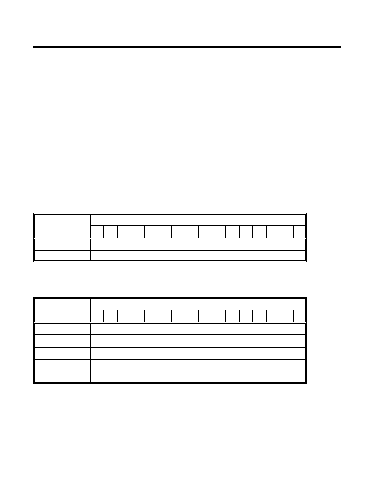
The last two rows of LEDs will be used to display the current value of the 9605 node address, SLC-500 (DH+)
node address, Watchdog file number, Watchdog element number, or Dialogue File number depending on which
parameter is selected. The value will be entered and displayed as a two digit BCD number (See figure 1).
Example
Perhaps the best way to describe the process of changing the Setup parameters is with an example: To set the
Dialogue File to B 24, the operator would:
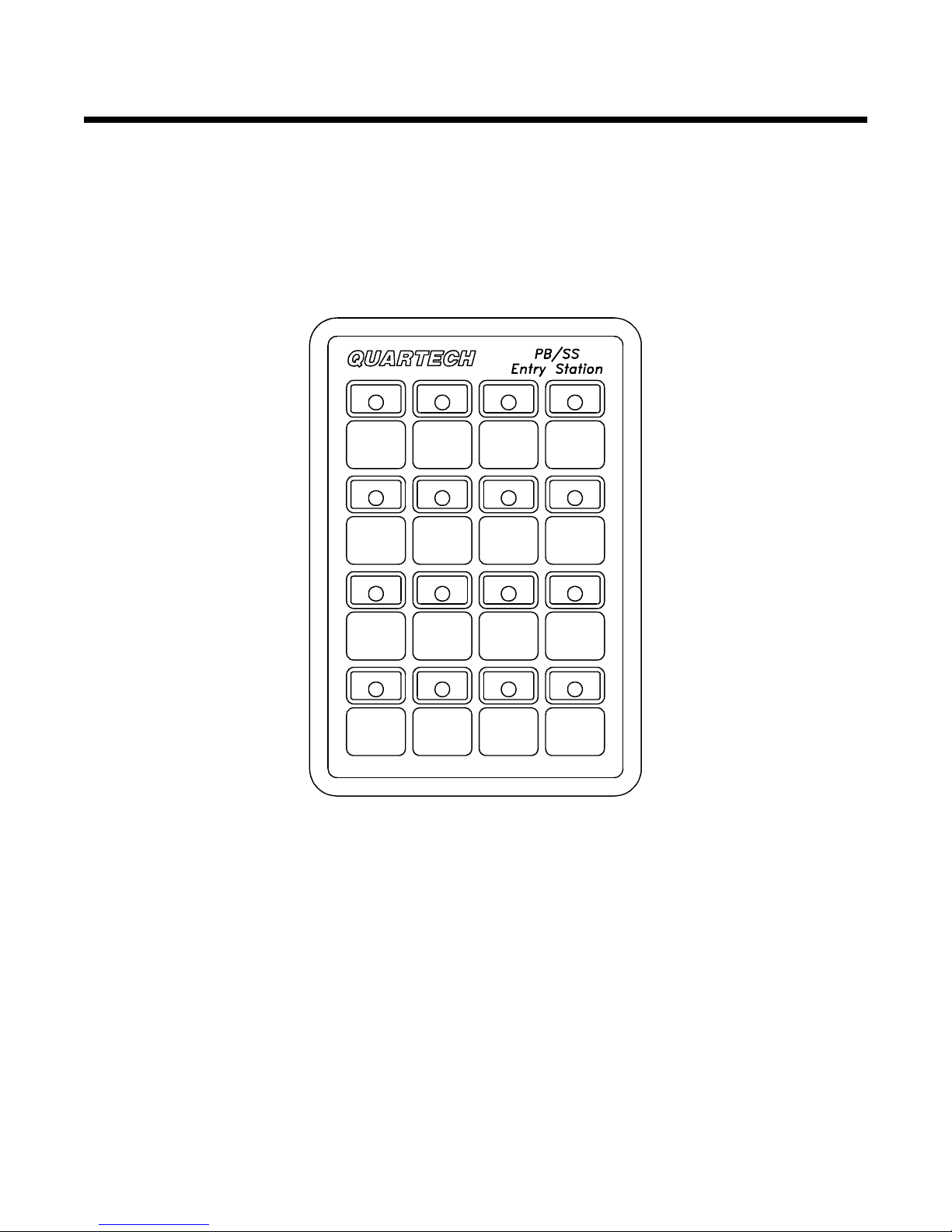
<Position the slide switch to the on position. Then apply the power to the 9605, to enter Setup Mode. If
Setup mode is entered properly the 9605 will cycle every LED green followed by the indicators turning off
with the exception of the Operating Mode LED.
<After power up, press the [5] key (see page 7 for key assignments). Notice how the number 5 led turns
Amber and the last two rows of LEDs change; The last two rows of LEDs display the current value of the
parameter. The value is a two digit BCD number. (See page 10 for a review of BCD numbers.)
<When LED 5 is amber, the Dialogue File number will be displayed in BCD. If you want to change this,
simply use the last two rows of keys to toggle the bits of the BCD number. A green LED means the bit is
zero (0); a red LED means the bit is one (1). You may press as many keys as needed to make up the
desired number. For the example, to make the Dialogue File 24, LEDs 11 and 14 need to be switched
Red the rest of the LEDs should be green. Once this LED pattern is set press the [5] key again to enter
this new value into memory. Note: If you don't press the [5] key a second time the changes will not be
saved.
<If your entry is accepted, the LEDs will turn off with the exception of the Operating Mode LED. If there is a
problem with your entry, the last two rows will flash amber and the 9605 will reject the new value. It will
return you to the parameter where you can adjust it to an acceptable value.
<Repeat the steps mentioned above to change any or all of the remaining setup parameters to match the
application needs. Keep in mind that SLC-500 uses the OCTAL numbering system for node addresses.
In that system any number with 8 or 9 is invalid, therefore keys 9 and 13 (normally used as BCD 8 for
other Setup parameters) will be disabled on the 9605 to prevent an illegal station address from being
entered.
<When the setup of the 9605 is complete, it is a good idea to view all of the setup parameters a second
time to insure that the proper values were entered in properly.
<When satisfied with the setup of the 9605, the slide switch must be placed in the off position. Once the
proper communication cable is attached, the 9605 can attempt to establish communications with the
processor by either pressing the [7] key (RESTART) or by cycling power to the 9605.

Page 8
PM9605 Revision 1, 9605 Version 36.1.1
BCD Numbers
Decimal
digit BCD Bit
8 4 2 1
00 0 0 0
10 0 0 1
20 0 1 0
30 0 1 1
40 1 0 0
50 1 0 1
60 1 1 0
70 1 1 1
81 0 0 0
91 0 0 1
Figure 1.
Setup Mode Switch and LED assignments.
BCD stands for Binary Coded Decimal. The BCD numbering scheme is a
convenient way of using the binary number system to encode a decimal
number. The basic idea is to use a separate four bit binary number to
represent each individual digit of the decimal number. The table to the left
shows the possible combinations for a one digit decimal number. The bits
of the BCD number sum to equal the decimal digit, if each bit is weighted
as shown at the top of the table. For example, look at number 6:
0110 <(0x8) + (1x4) + (1x2) + (0x1) = 6.
Also, for number 9:
1001 <(1x8) + (0x4) + (0x2) + (1x1) = 9.
The 9605 uses BCD numbers to display some Setup Mode parameters.
The 10's digit is displayed on the third row (LEDs 9-12), and the 1's digit is
displayed on the fourth row(LEDs 13-16). For example, to set the Dialogue
file equal to 69, LEDs 10, 11, 13, and 16 must be red and all the rest of the
LEDs must be green.

Section 3: Setup Mode Page 9
PM9605 Revision 1, 9605 Version 36.1.1
3.2 Test Diagnostic Mode
The 9605, while in Setup mode, has a keyboard and communication diagnostic test built in. Test Mode can be
accessed by pressing the [8] key while in Setup mode or by holding down any key during power up when the slide
switch is off. All LEDs will turn off except LED 1,2,& 3 which will flash green. Press the desired key 1,2, or 3 to
begin the tests which are described below:
1Keyboard test This test will verify the integrity of the individual switches. The associated LED will
illuminate upon pressing a particular key. If the LED does not illuminate with the
action of the switch, the keyboard may be damaged.
2LED test This test will prove that power is reaching all of the printed circuit boards and the
microprocessor is operating. Upon entry into this test the LEDs will cycle one by one
in the green color state and repeat for the other LED colors. If one or more of the
LEDs do not cycle they may be faulty.
3Communication This test functions like the LED test, but its purpose is to exercise and test the
electronics associated with the communication port on the 9605. If the port is
functional the LEDs will cycle one by one in the green color state, and repeat for the
other LED colors. If the port is not functional the 9605 will signal an error.

Appendices: Page 10
PM9605 Revision 1, 9605 Version 36.1.1
Appendix A: Communication Basics
The 9605 communicates with the Allen-Bradley SLC-500 processor using the Data Highway Plus (DH+) network.
The 9605 can communicate on the DH+ network along with other 9605's, other Quartech peripherals,
Allen-Bradley's programming software, other programmers, and any other device that strictly follows the SLC-500
DH+ protocol. Several Quartech peripherals and a programming device may communicate with a single SLC-500
at the same time. The 9605 can communicate with any one, but only one, SLC-500 at any time. The operator
cannot select between multiple SLC-500's that may be on the network.
The physical connection between the 9605 and SLC-500 processor is through the Three position terminal block.
The 9605 provides both a nine pin D-type connector and a three position terminal block for making the physical
connection. In either case the communication cable must be twinaxial cable (Belden type 9463 or equivalent).
When multiple devices are to share the Data Highway Plus network the physical data highway cabling must
conform to specific rules. For in-depth information please refer to the Allen-Bradley Data Highway Cable Assembly
and Installation Manual (Publication 1770-6.2.1).
The example on the following page shows the physical cabling for a system having one SLC-500 processor, two
Quartech 9605 Pushbutton Stations, and a programming device.

Appendices: Page 11
PM9605 Revision 1, 9605 Version 36.1.1
Computer
9605 9605
SLC500
A DH+ network is constructed with a main trunkline and optional droplines. In the example above the trunkline
runs from one 9605 to the SLC-500 and onto the second 9605 in a simple daisy chain fashion. The programmer is
connected to the SLC-500 via channel 0(DF1). A terminating resistor must be connected at each end of the
trunkline to provide proper line loading thus reducing signal interference. Devices intended for use on the DH+
network must include, as part of their interface hardware, a line terminating resistor and a method for switching it
in or out of the circuit. The line termination switch on the 9605 enables the termination resistor when set on. The
terminating resistors on both 9605's would be enabled in the above example since they are located at either end of
the trunkline. The terminating resistor on the SLC-500 processor and programming terminal must be off.

Appendices: Page 12
PM9605 Revision 1, 9605 Version 36.1.1
Appendix B: Error Codes
The 9605 will display the following error codes if it encounters a hardware or communication error that it cannot
recover from without help from an operator. An error code is displayed similar to the display of Setup mode
parameters. The last two rows of LEDs will display a BCD value which will indicate the error and the top two rows
will cycle Green, Amber, and Red which indicates that the 9605 is displaying an error code. The following table
will list all of the possible errors and list common causes for the error. After taking appropriate action to correct the
error, press any key to "reboot" the 9605.
Note: Some of the errors below are very uncomon and in most cases will never be seen. Because
these errors are so uncomon they need to be discussed on an individual application basis.
If you encounter one of these errors please contact Quartech.
Error Description Troubleshooting
11 RAM read/write error. Low power supply voltage or chip failure. Adjust the
supply, if the problem continues contact Quartech for
possible repair.
12 ROM checksum error.
13 EEPROM checksum error. - Low or Noisy power supply voltage.
- Slide switch was left in the on position. It should only be on
during Setup Mode.
15 EEPROM write disabled. Slide switch is not in the on position.
21 No activity on the network. Communication cable not attached on power up.
Check the cable for connections and possible breaks in
the wires. Also make sure PLC is powered up.
22 Not invited to join network. Contact Quartech for information.
23 Acknowledge Timeout. The 9605 did not recieve a response to a command.
If connecting for the first time check the PLC node
address entered during setup, it may not be correct.
24 Reply Timeout. Contact Quartech for information.
25 Unknown command or reply. Contact Quartech for information.
26 Unrequested reply. Contact Quartech for information.
28 Can't replace lost successor. The 9605 and the PLC are the only devices online and
the PLC has dropped off the network.
29 Kicked off network. During normal operation, communications with the
9605 has been disrupted. Check the power to the PLC
and the communication cable.
31 PLC in Program Mode The keyswitch on the PLC is in Program mode. The
9605 is communicating but will continue to display the
error until the keyswitch is moved to Run mode.
32 PLC in Remote Program
Mode The PLC is in Remote Program mode. The 9605 is
communicating with the PLC but will continue to display the
error until it is put into Run mode.

Appendices: Page 13
PM9605 Revision 1, 9605 Version 36.1.1
The remainder of the error codes are configuration or test mode oriented. These errors also require assistance
from the operator.
D_File = Dialogue File WD File = Watchdog File
Error Description Possible Cause
41 D_file does not exist.
D_file not a bit file.
Not enough D_file elements.
The D_File entered during setup does not exist in the PLC, or it
is not a bit file. The bit file may not be large enough to support
the operating mode selected during setup.
42 Failure writing D_File. The 9605 was unable to change and update its D_file.
Restart 9605 and check connection of comm. cable.
44 WD file does not exist.
WD file not a timer file.
Not enough WD file elements
The WD File entered during setup does not exist in the PLC, or
it is not a timer file. The timer file may not be large enough to
contain the element # selected during setup.
47 Duplicate node address. The 9605 station address entered during setup is occupied by
another device on a network.
81 Channel A no byte received. The communication test has failed. Cycle power to the 9605
and try the test again. If the problem still exist contact Quartech
for repair information.
82 Channel B no byte received.
If you encounter any of these errors and cannot get the 9605 to recover after checking into the causes contact the
Quartech Corporation technical staff for more information.
For Technical Assistance please call:
Quartech Corporation
50680 Corporate Drive
Shelby Township, MI 48315-3107
Technical Assistance: (810) 997-9400
Fax: (810) 997-9407

Appendices: Page 14
PM9605 Revision 1, 9605 Version 36.1.1
Appendix C: Installation
The 9605 is designed to be mounted in the door of an enclosure or on an operators console for ease of use. A
template is provided to assist in the drilling and cutting of the mounting holes for the unit. Care should be taken to
protect the unit from metal chips and conductive particles. Failure to protect the unit may cause damage when
power is applied and may void warranty.
A minimum clearance of six inches should be kept between the unit and any other device that generates heat. In
the event that the internal enclosure temperature periodically exceeds 55 degrees Celsius (131 degrees
Fahrenheit), fans or a purge air system should be used to increase the air flow, and eliminate "Hot Spots" that
occur within the panel.
Electrical Requirements
Power to the 9605 must be provided by an external power supply meeting the following requirements:
Output voltage: 5.1 VDC to 5.3 VCD at 30 mV max. ripple.
Output current: 450 mA (Minimum) .
Quartech Model 8552 power supply is an excellent choice for most applications.
Environment:
Operating Temperature: ............ 0°c to 60°c
Storage Temperature .............. -20°c to 70°c
Operating Humidity ................ 0% to 95% (non-condensing)
Storage Humidity ................. 0% to 95% (non-condensing)
Vibration (10Hz to 55Hz) ........... Displacement: 0.5mm, Constant X,Y,Z axis
Shock .......................... 40G
Wiring Considerations
Care should be taken when routing DC power supply cable and the communication cable. Follow these guidelines
for a trouble free installation.
‚The power supply should be mounted as close as possible to the 9605. If the 9605 is to be mounted a
long distance from the SLC-500, the power supply should be mounted local to the 9605 to allow short
supply cables.
‚Use at least 16 AWG wire for the 5 VDC power supply cable. If the 9605's power source
must be 10 ft or longer 14 AWG wire should be used. Do not make a power supply cable
longer than 20 ft.
‚The DC power lines and communication cable must be kept away from AC power lines. Keep both at
least one foot away from 120 VAC lines, and two feet away from higher voltage lines. This especially
applies to the communication cable. If the cables must cross AC power lines, cross them at right angles
(90°).
‚Keep the cables away from sources of high energy fields such as arc welders, AC motors, motor starters,
servo controllers, generators, induction heaters, and transformers.

Appendices: Page 15
PM9605 Revision 1, 9605 Version 36.1.1
Appendix D: Legend Cards
The 9605 allows the user to customize the legend area beneath each LED. A pocket between the layers of the
polycarbonate is accessed by pealing the gasket back from the faceplate. The pocket extends completely across
the faceplate to aid in removal of the tags.
A sheet of blank legend strips has been included. The area for customizing will allow three lines by nine
charactersof type (12 cpi). The strip measures 4 x 0.7 inches (0.01 inch max. thickness).
Quartech can provide custom legends produced to your specifications. Custom graphics and color may be
included in each legend. Contact Quartech Customer Service for price and delivery.
The 9605 is gasketed for NEMA 12 panel applications. However, under high humidity conditions a NEMA 4 rating
can be accomplished by sealing the gasket to the polycarbonate faceplate. This may be accomplished by using
either a black RTV sealant or LOCTITE 403 gel adhesive. Use of the LOCTITE will make the seal permanant,
where as the RTV can be pealed off if desired.
Appendix E: Mechanical Dimensions

Table of contents
Popular Keypad manuals by other brands

Contro l4
Contro l4 C4-SKC installation guide

IntelliControl ICS
IntelliControl ICS Contact-TT Quick install guide

BENSHAW
BENSHAW ENHANCED KEYPAD manual

Comelit
Comelit VEDO5TPR Technical manual

DMP Electronics
DMP Electronics 7000INT Series Installation and programming guide

LEGRAND
LEGRAND 0 767 17 manual