AL-KO AMS2 MAMMUT TANDEM User manual

1653922_a I 12/ 2014
AMS2 MAMMUT EINACHS / TANDEM
Montageanleitung Hinten Obeneinbau

DAMS2 Mammut Einachs / Tandem
2 Montageanleitung
Inhaltsverzeichnis
D .................................................................................................................................................................... 4
EN .................................................................................................................................................................... 8
NL .................................................................................................................................................................. 12
FR .................................................................................................................................................................. 16
IT .................................................................................................................................................................. 20
DA .................................................................................................................................................................. 24
SV .................................................................................................................................................................. 28
FI .................................................................................................................................................................. 32
© 2014
AL-KO KOBER GROUP Kötz, Germany
This documentation or excerpts therefrom may not be reproduced or dis-
closed to third parties without the express permission of the AL-KO
KOBER GROUP.

1653922_a 3
min. 20mm
max. 35mm
a

D
4 Montageanleitung
Montage Hinten Obeneinbau
Zu dieser Dokumentation
Lesen Sie diese Dokumentation vor der Inbetriebnahme durch. Dies ist Voraussetzung für sicheres
Arbeiten und störungsfreie Handhabung.
Beachten Sie die Sicherheits- und Warnhinweise in dieser Dokumentation und auf dem Produkt.
Diese Dokumentation ist permanenter Bestandteil des beschriebenen Produkts und soll bei Veräuße-
rung dem Käufer mit übergeben werden.
Zeichenerklärung
ACHTUNG!
Genaues Befolgen dieser Warnhinweise kann Personen- und / oder Sachschäden vermeiden.
HINWEIS
Spezielle Hinweise zur besseren Verständlichkeit und Handhabung.
Sicherheitshinweise
GEFAHR!
Achtung - Lebensgefahr!
Arbeiten unter dem Fahrzeug ohne geeignete Abstütz- und Sicherheitsmaßnahmen sind lebens-
gefährlich! Verwenden Sie immer eine Hebebühne oder eine Montagegrube und sichern Sie ihren
Caravan gegen Eigenbewegungen.
Bei der Montage dürfen keine Teile vom Fahrgestell, der Achsaufhängung oder der Bremsvorrichtung
abmontiert, verändert oder beeinträchtigt werden.
Tragen Sie bei der Montage Schutzhandschuhe und Schutzbrille.
Säubern Sie vor der Montage die Rahmenteile
von Feuchtigkeit und Schmutz
und trennenden oder benetzenden Substanzen.
Installieren Sie keine Batterie im Gaskasten.

Montage Hinten Obeneinbau
1653922_a 5
Lieferumfang
1
2
1
4
5
3
3
7
8
9
6
10
//
10 mm
13 mm
19 mm
86 Nm
11
1 2x Traversenanschluss 7 4x Sechskantschraube M12x30
2 1x Mitteltraverse 8 10x Mutter M12, selbstsichernd
3 2x Anlage außen 9 4x Kunststoff-Gewindestifte
4 2x Distanzeinlage 15 mm 10 14x Scheibe 13 mm
5 2x Distanzeinlage 10 mm 11 Werkzeuge (nicht im Lieferumfang)
6 6x Schlossschraube M12x55
HINWEIS
Wir empfehlen alle Montagearbeiten nur durch kompetente Fachbetriebe oder unsere AL-KO Ser-
vicestellen durchführen zu lassen.
Montage
Voraussetzung
AL-KO Fahrgestell mit freigegebenen Montagebohrungen
Fremdchassis mit herstellerseitig eingebrachten und freigegebenen Montagebohrungen.
Maß zwischen Reifeninnenseite und Rahmen: mindestens 125 mm.
Montagebereich frei von Leitungen und Lüftungsrohren.
Montage mit zwei Personen durchführen.
Montage nur hinter der Achse möglich.

D
6 Montageanleitung
Arbeitsschritte
HINWEIS
Die Arbeitsschritte dieser Montage sind spiegelbildlich auf jeder Seite durchzuführen. Ausnahme:
Punkt 13.
Die Abbildungen bezieht sich auf die Bildseite am Heftanfang.
1. Bringen Sie ihren Caravan auf eine komfortable Arbeitshöhe und sichern Sie ihn.
2. Messen Sie den Abstand zwischen Radinnenseite und Rahmen (1).
3. Ziehen Sie vom gemessenen Wert 115 mm ab.
➯Wird kein Wert ermittelt, der den Distanzeinlagen entspricht, runden Sie das Ergebnis nach unten ab.
Beispiel 1 gemessen: 129 mm (129 -115 = 14) Distanzeinlage 10 mm ver-
wenden
Beispiel 2 gemessen: 140 mm (140 -115 = 25) Distanzeinlagen 10 und
15 mm verwenden
4. Stellen Sie die Distanzeinlagen für ihr Fahrzeug zusammen. Verwenden Sie hierzu die beiliegenden
Kunststoff- Gewindestifte (2).
➯Die Kombinationen der Distanzeinlagen muss auf jeder Seite gleich sein! Mind. Distanzeinlage:
10 mm.
5. Setzen Sie die passenden Schloss-Schrauben (3 -a) in das Führungsprofil .
bis 25 mm Distanz: 12x55
6. Stecken Sie die benötigten Distanzeinlagen (3 -b) auf die Schloss-Schrauben.
7. Die Anlage außen (4 -a) an die Rahmenaußenseite halten und den Traversenanschluss (4 -b) in die
Lasche einfädeln.
HINWEIS
Wir empfehlen den Arbeitsschritt 8. mit zwei Personen durchzuführen!
8. Setzen Sie den Mammutantrieb mit den Schrauben in die vorhandenen Aufnahmebohrungen des
Rahmens ein (5).
9. Unterlegscheiben und Muttern montieren. Ziehen Sie die Muttern handfest an.
➯der Traversenanschluss ist gesichert.
10.Diesen Schritt nur bei Tandem Einbau ausführen.
Markieren Sie die weißen Kabelstecker vom Mammutantrieb mit einem wasserfesten Stift.
1 = Antrieb vorne links 3 = Antrieb hinten links
2 = Antrieb vorne rechts 4 = Antrieb hinten rechts
3
4
1
2
11.Führen Sie das Kabel vom Mammutantrieb an einer geeigneten Stelle durch das Rahmenteil bzw.
unter dem Rahmenteil durch.

Montage Hinten Obeneinbau
1653922_a 7
12.Stecken Sie die Mitteltraverse auf die Anschlusstücke.
13.Setzen Sie die Schrauben M12x30 mit Unterlegscheiben und Muttern in die Langlöcher ein und mitteln
Sie das Traversenstück aus (7).
➯Die Überdeckung mit dem Traversenanschluss soll beidseitig gleich sein!
14.Platzieren Sie den Mammutantrieb im richtigen Abstand zum Rad und ziehen Sie die Muttern handfest
an (8).
➯Benutzen Sie zur Überprüfung den beiliegenden Distanzklotz: 20x20x35 mm (8-a). Abstand Rad zu
Mammutwalze: 20 mm.
15.Ziehen Sie die Schrauben am Traversenmittelstück handfest an.
16.Lassen Sie das Fahrzeug ab, prüfen bei eingefedertem Rad die Abstände erneut und justieren eventu-
ell nach (1 / 8).
17.Bringen Sie ihren Caravan wieder auf eine komfortable Arbeitshöhe und sichern Sie ihn.
18.Richten Sie den Mammutantrieb waagerecht aus.
19.Ziehen Sie anschließend alle Schrauben mit einem Drehmoment von 86 Nm an.

en
8 Assembly instructions
Rear assembly from the top
About this documentation
Read this documentation before starting up the machine. This is a precondition for safe working and
flawless operation.
Observe the safety warnings in this documentation and on the product.
This documentation is a permanent integral part of the product described and must be passed on to the
new owner if the product is sold.
Explanation of symbols
CAUTION!
Following these safety warnings carefully can prevent personal injury and/or material damage.
ADVICE
Special instructions for greater ease of understanding and improved handling.
Safety instructions
DANGER!
Important – Danger of fatal injury!
Working under the vehicle without suitable support and safety measures represents a risk of fatal
injury! Always use a lifting platform or an assembly pit, and secure your caravan to prevent inad-
vertent movements.
Do not remove, modify or impair any parts of the chassis, the axle suspension or the brake device during
installation.
Wear protective gloves and protective glasses during installation.
Clean the frame parts before installation
to remove moisture and dirt
as well as parting or wetting substances.
Do not install any batteries in the gas box.

Rear assembly from the top
1653922_a 9
Scope of delivery
1
2
1
4
5
3
3
7
8
9
6
10
//
10 mm
13 mm
19 mm
86 Nm
11
1 2x cross beam connection 7 4x hexagon bolts M12x30
2 1x centre cross beam 8 10x nuts M12, self-locking
3 2x exterior attachments 9 4x plastic threaded pins
4 2x spacers 15 mm 10 14x washers 13 mm
5 2x spacers 10 mm 11 Tools (not included in the scope of delivery)
6 6x carriage bolts M12x55
ADVICE
We recommend having all installation work carried out only by competent specialist workshops or
our AL-KO Service Centres.
Assembly
Requirement
AL-KO chassis with approved assembly holes
Third-party chassis with assembly holes provided and released by the manufacturer.
Dimension between the inner tyre side and frame: min. 125 mm.
Assembly area free of lines and ventilation pipes.
Assembly must be carried out by two persons.
Assembly can only be performed behind the axle.

en
10 Assembly instructions
Work steps
ADVICE
The work steps for this assembly must be carried out as a mirror image for each side. Exception:
Point 13.
The illustration refers to the image page at the beginning of the booklet.
1. Bring your caravan to a comfortable work height and secure it.
2. Measure the distance between the inner tyre side and the frame (1).
3. Subtract 115 mm from the measured value.
➯If you don't get a value that matches the spacers, then round down the result.
Example 1 measured: 129 mm (129 -115 = 14) Use spacer 10 mm
Example 2 measured: 140 mm (140 -115 = 25) User spacer 10 and 15 mm
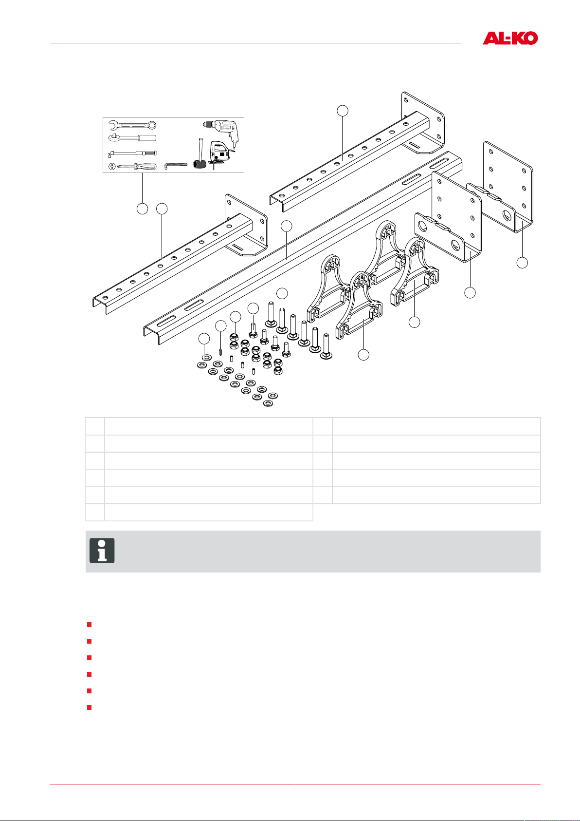
4. Put together the spaces for the vehicle. For this purpose, use the included plastic threaded pins (2).
➯The combination of spaces must be the same on both sides! Min. spacer: 10 mm.
5. Insert the right carriage bolts (3 -a) into the guide profile.
Up to 25 mm distance: 12x55
6. Place the required spacers (3 -b) onto the carriage bolts.
7. Hold the exterior attachments (4 -a) onto the outside of the frame and thread the cross beam connec-
tion (4 -b) into the lug.
ADVICE
We recommend performing work step 8 with two persons!
8. Insert the Mammut drive with the bolts into the available attachment holes of the frame (5).
9. Install the washers and nuts. Tighten the nuts by hand.
➯The cross beam connection is secured.
10.Only perform this step for the tandem installation.
Mark the white cable plug from the Mammut drive with a water-proof pen.
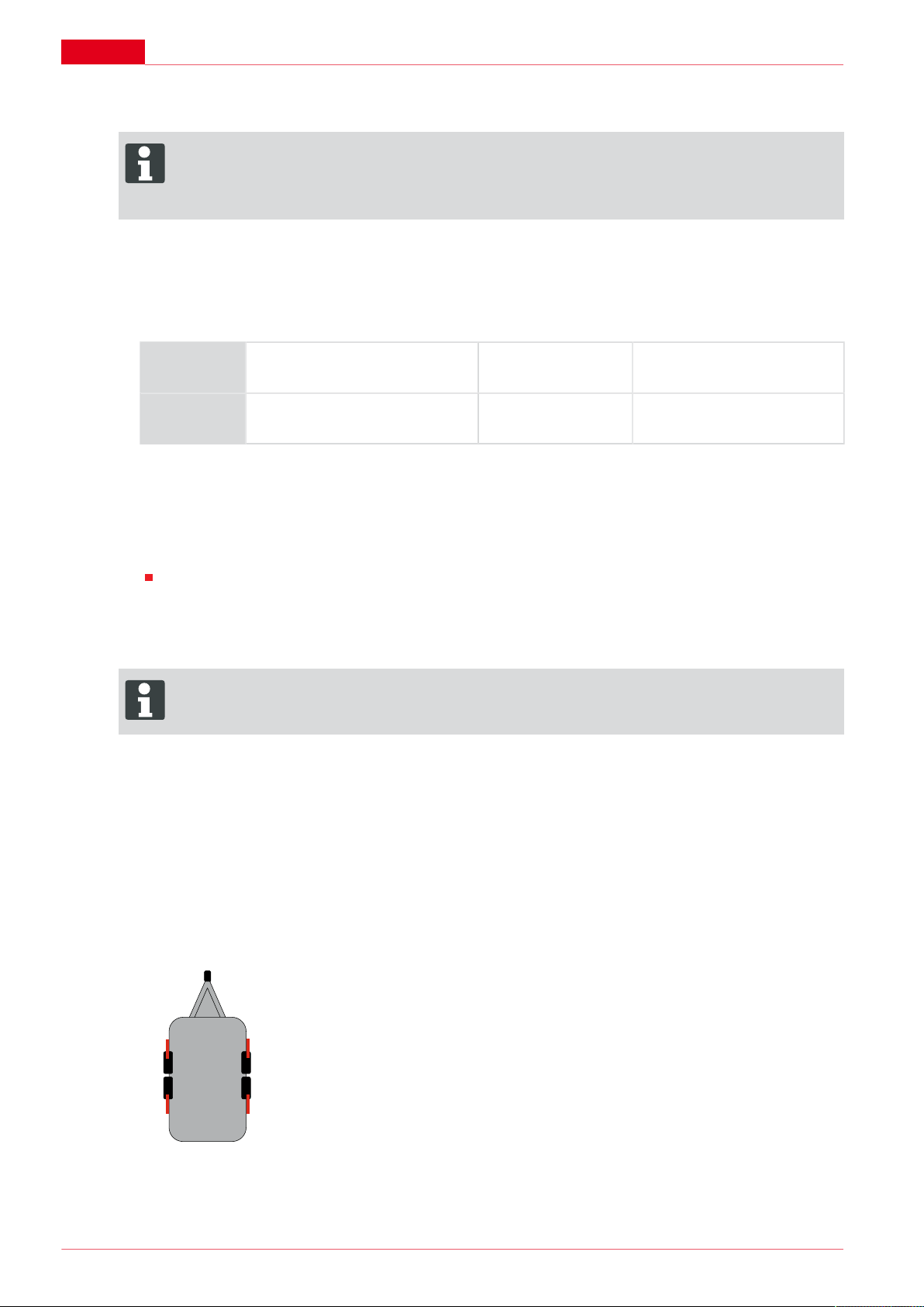
1 = Drive front left 3 = Drive rear left
2 = Drive front right 4 = Drive rear right
3
4
1
2
11.Lay the cable of the Mammut drive to the suitable location through the frame part and/or under the
frame part.
12.Insert the centre cross beam into the connectors.
13.Insert the M12x30 bolts with the washers and nuts in the elongated holes and take the mean of the
cross beam piece (7).
➯The overlap with the cross beam connection should be the same on both sides!

Rear assembly from the top
1653922_a 11
14.Set the Mammut drive to the right distance from the wheel and tighten the nuts by hand (8).
➯Use the included distance block to check your work: 20x20x35 mm (8-a). Distance of wheel to Mam-
mut roller: 20 mm.
15.Tighten the bolts on the cross beam centre piece by hand.
16.Lower the vehicle and check the distance when the wheel is compressed and adjust if necessary
according to (1 / 8).
17.Move your caravan again to a comfortable work height and secure it.
18.Level the Mammut drive.
19.Then tighten all bolts to a torque of 86 Nm.

nl
12 Montagehandleiding
Montage achter boveninbouw
Over deze documentatie
Lees deze documentatie vóór ingebruikname door. Dit is een voorwaarde voor veilig werken en sto-
ringsvrij gebruik.
Neem de veiligheidsvoorschriften en waarschuwingen in deze documentatie en op het product in acht.
Deze documentatie is permanent onderdeel van het beschreven product en dient bij verkoop aan de
koper te worden overgedragen.
Legenda
LET OP!
Het nauwkeurig in acht nemen van deze waarschuwingen kan verwondingen en/of materiële
schade voorkomen.
ADVICE
Speciale aanwijzingen voor een beter begrip en gebruik.
Veiligheidsvoorschriften
GEVAAR!
Let op - levensgevaar!
Werkzaamheden onder het voertuig zonder passende stut- en veiligheidsmaatregelen zijn levens-
gevaarlijk! Gebruik altijd een hefbrug of een werkkuil en maak de caravan vast om bewegingen
te voorkomen.
Bij de montage mogen er geen onderdelen van het chassis, de asophanging of de reminrichting worden
gedemonteerd, gewijzigd of beschadigd.
Draag beschermende handschoenen en een veiligheidsbril tijdens de montage.
Maak voorafgaand aan de montage de framedelen vrij van
vocht en vuil
en coatings- of bevochtigingsmiddelen.
Installeer geen accu in de gaskast.

Montage achter boveninbouw
1653922_a 13
Inhoud van de levering
1
2
1
4
5
3
3
7
8
9
6
10
//
10 mm
13 mm
19 mm
86 Nm
11
1 2 x dwarsbalkverbinding 7 4 x zeskantbout M12x30
2 1 x middendwarsbalk 8 10 x moer M12, zelfborgend
3 2 x mechanisme buiten 9 4 x kunststof draadeinden
4 2 x vulplaat 15 mm 10 14 x onderlegring 13 mm
5 2 x vulplaat 10 mm 11 Gereedschap (niet meegeleverd)
6 6 x slotschroef M12x55
ADVICE
Wij adviseren alle montagewerkzaamheden uitsluitend door competente vakbedrijven of door onze
AL-KO servicestations te laten uitvoeren.
Montage
Voorwaarden
AL-KO chassis met vrijgegeven montagegaten
Chassis van derden met door de fabrikant aangebrachte en vrijgegeven montagegaten.
Afstand tussen de binnenzijde van de band en het frame: minimaal 125 mm.
Montagegedeelte vrij van kabels en ventilatiebuizen.
Voer de montage met twee personen uit.
Montage is uitsluitend mogelijk achter de as.

nl
14 Montagehandleiding
Montagestappen
ADVICE
De montagestappen bij deze montage moeten aan beide kanten in spiegelbeeld worden uitgevo-
erd. Uitzondering: punt 13.
De afbeeldingen hebben betrekking op de geïllustreerde pagina aan het begin van het handboek.
1. Zet uw caravan op een prettige werkhoogte en zet deze goed vast.
2. Meet de afstand tussen de binnenkant van het wiel en het frame (1).
3. Trek 115 mm van de gemeten afstand af.
➯Als er geen waarde overblijft die overeenkomt met de vulplaten, rondt u het resultaat naar beneden
af.
Voorbeeld 1 gemeten: 129 mm (129 -115 = 14) Vulplaten van 10 mm gebrui-
ken
Voorbeeld 2 gemeten: 140 mm (140 -115 = 25) Vulplaten van 10 en 15 mm
gebruiken
4. Monteer de vulplaten voor uw voertuig aan elkaar. Gebruik hiervoor de meegeleverde kunststof draad-
einden (2).
➯De combinatie van vulplaten moet voor elke zijde gelijk zijn! Vulplaat minimaal: 10 mm.
5. Plaats de juiste slotschroeven (3 -a) in het geleideprofiel.
tot 25 mm afstand: 12 x 55
6. Plaats de benodigde vulplaten (3 -b) op de slotschroeven.
7. Houd het mechanisme (4 -a) tegen de buitenkant van het frame en plaats de dwarsbalkverbinding (4 -
b) in het lipje.
ADVICE
Wij adviseren om montagestap 8 met twee personen uit te voeren!
8. Plaats de Mammut-aandrijving met de schroeven in de aanwezige bevestigingsgaten van het frame
(5).
9. Monteer de onderlegringen en moeren. Draai de moeren handvast aan.
➯De dwarsbalkverbinding is geborgd.
10.Voer deze montagestap uitsluitend bij een tandem-asser uit.
Markeer de witte kabelstekker van de Mammut-aandrijving met een watervaste stift.
1 = aandrijving linksvoor 3 = aandrijving linksachter
2 = aandrijving rechtsvoor 4 = aandrijving rechtsachter
3
4
1
2
11.Steek de kabel van de Mammut-aandrijving op een geschikte plek door het framegedeelte of onder
het framegedeelte door.

Montage achter boveninbouw
1653922_a 15
12.Plaats de middendwarsbalk op de verbindingsstukken.
13.Steek de schroeven M12x30 met onderlegringen en moeren in de langgaten en centreer het dwars-
balkstuk (7).
➯De overlap met de dwarsbalkverbinding moet aan beide kanten gelijk zijn!
14.Plaats de Mammut-aandrijving op de juiste afstand tot het wiel en draai de moeren handvast aan (8).
➯Gebruik het meegeleverde afstandsblok: 20 x 20 x 35 mm (8-a). Afstand wiel tot Mammut-rol: 20 mm.
15.Draai de schroeven van de middendwarsbalk handvast aan.
16.Laat het voertuig zakken en controleer bij een ingeveerd wiel de afstanden opnieuw en stel deze
eventueel bij (1 / 8).
17.Breng de caravan weer op een prettige werkhoogte en zet de caravan vast.
18.Zorg dat de Mammut-aandrijving waterpas is uitgelijnd.
19.Draai daarna alle schroeven aan met een aantrekkoppel van 86 Nm.

fr
16 Notice de montage
Montage par l'arrière et intégration par en haut
À propos de cette documentation
Veuillez lire cette documentation avant la mise en service. Ceci est indispensable pour pouvoir effectuer
un travail fiable et une manipulation sans difficulté.
Veuillez respecter les remarques relatives à la sécurité et les avertissements figurant dans cette docu-
mentation et sur le produit.
Cette documentation est partie intégrante du produit décrit et devra être remise au client lors de la vente.
Explication des symboles
ATTENTION!
Le respect de ces avertissements permet d’éviter des dommages corporels et / ou matériels.
ADVICE
Remarques spéciales pour une meilleure compréhension et manipulation.
Consignes de sécurité
DANGER!
Attention - danger de mort !
Tout travail sous le véhicule sans la prise de mesures de support et de sécurité adaptées présente
un danger de mort ! Utilisez systématiquement une plateforme de levage ou une fosse de montage
et bloquez votre caravane contre tout déplacement propre.
Lors du montage, aucune pièce du châssis, de la suspension de l'essieu ou du dispositif de freinage ne
doit être démontée, modifiée ou altérée de quelque manière que ce soit.
Pour le montage, porter des gants et des lunettes de protection.
Avant le montage, nettoyez les pièces du cadre
de toute humidité ou encrassement
et de toutes substances entraînant une mauvaise adhérence ou mouillées.
N'installez pas de batterie dans le coffre à gaz.

Montage par l'arrière et intégration par en haut
1653922_a 17
Contenu de la livraison
1
2
1
4
5
3
3
7
8
9
6
10
//
10 mm
13 mm
19 mm
86 Nm
11
1 2x raccords de traverse 7 4x vis hexagonales M12x30
2 1x traverse centrale 8 10x écrous M12, autobloquants
3 2x supports extérieurs 9 4x tiges filetées en plastique
4 2x entretoises, 15 mm 10 14x rondelles 13 mm
5 2x entretoises, 10 mm 11 Outils (non fournis)
6 6x boulons M12x55
ADVICE
Nous conseillons de ne faire effectuer tous les travaux de montage que par des entreprises spé-
cialisées compétentes ou par nos points de service après-vente AL-KO.
Montage
Conditions requises
Châssis AL-KO à alésages de montage validés
Châssis tiers à alésages de montage exécutés par le fabricant et validés.
Distance entre le flanc intérieur du pneu et le cadre : au moins 125 mm.
Zone de montage exempte de conduites et de tuyaux d'aération.
Réaliser le montage avec deux personnes.
Montage possible derrière l'essieu uniquement.

fr
18 Notice de montage
Opérations
ADVICE
Les opérations de montage doivent être exécutées symétriquement de chaque côté. Exception :
point 13.
Les illustrations se rapportent aux page du début du livret.
1. Placez votre caravane à une hauteur de travail confortable et bloquez-la en position.
2. Mesurez la distance entre le flanc intérieur du pneu et le cadre (1).
3. Retirez 115 mm de la valeur mesurée.
➯Si la valeur calculée ne correspond pas à la mesure des entretoises, arrondissez le résultat au chiffre
inférieur.
Exemple 1 mesuré : 129 mm (129 -115 = 14) Utiliser l'entretoise de 10 mm
Exemple 2 mesuré : 140 mm (140 -115 = 25) Utiliser les entretoises de 10
et 15 mm
4. Assemblez les entretoises pour votre véhicule. Pour cela, utilisez les tiges filetées en plastique four-
nies (2).
➯Les combinaisons d'entretoises doivent être identiques des deux côtés ! Entretoise min. : 10 mm.
5. Insérez les boulons correspondants dans le profilé de guidage (3 -a).
jusqu'à 25 mm : 12x55
6. Placez les entretoises nécessaires (3 -b) sur les boulons.
7. Tenir les supports extérieurs (4 -a) sur la face extérieure du châssis et passer le raccord de traverse
(4 -b) dans la patte.
ADVICE
Nous recommandons de réaliser l'étape 8 à deux personnes !
8. Installez l'entraînement Mammut avec les vis dans les alésages du cadre prévus à cet effet (5).
9. Poser les rondelles et les écrous. Serrez les écrous à la main.
➯Le raccord de traverse est fixé.
10.Exécuter cette opération exclusivement pour le montage sur une caravane Tandem.
Marquez les connecteurs de câble blancs de l'entraînement Mammut au marqueur indélébile.
1 = Entraînement avant gauche 3 = Entraînement arrière gauche
2 = Entraînement avant droit 4 = Entraînement arrière droit
3
4
1
2
11.Faites passer le câble de l'entraînement Mammut par une partie adaptée du cadre ou sous une partie
du cadre.
12.Enfichez la traverse centrale sur les raccords.

Montage par l'arrière et intégration par en haut
1653922_a 19
13.Placez les vis M12x30, ainsi que les rondelles et écrous dans les orifices oblongs et centrez la tra-
verse (7).
➯Le chevauchement avec le raccord de traverse doit être identique des deux côtés !
14.Placez l'entraînement Mammut à une distance adaptée de la roue et serrez les écrous à la main (8).
➯Contrôlez l'écartement à l'aide du bloc d'écartement fourni : 20x20x35 mm (8-a). Écartement de la
roue au cylindre Mammut : 20 mm.
15.Serrez les vis de la pièce centrale de traverse à la main.
16.Abaissez le véhicule et contrôlez à nouveau les écartements une fois la roue reposant sur sa suspen-
sion à ressort. Au besoin, ajustez (1 / 8).
17.Replacez votre caravane à une hauteur de travail confortable et bloquez-la.
18.Installez l'entraînement Mammut à l'horizontale.
19.Serrez ensuite toutes les vis à un couple de 86 Nm.

it
20 Istruzioni di montaggio
Montaggio posteriore dall'esterno
Informazioni sulla documentazione
Leggere la presente documentazione prima della messa in funzione. Ciò è indispensabile per garantire
il funzionamento sicuro e l'uso corretto.
Attenersi alle indicazioni di sicurezza e alle avvertenze contenute in questa documentazione e presenti
sul prodotto.
La presente documentazione è parte integrante del prodotto descritto e in caso di cessione deve essere
consegnata all'acquirente.
Spiegazione dei simboli
ATTENZIONE!
Seguire attentamente queste avvertenze per evitare danni a persone e / o materiali.
ADVICE
Indicazioni speciali per maggiore chiarezza e facilità d'uso.
Indicazioni di sicurezza
PERICOLO!
Attenzione - pericolo di morte!
Lavorare sotto il veicolo senza adeguate misure di sostegno e sicurezza è estremamente perico-
loso! Utilizzare sempre una piattaforma elevatrice o una fossa di montaggio e assicurare il camper
da movimenti incontrollati.
Durante il montaggio non è consentito smontare, modificare o compromettere parti del telaio, della
sospensione o del dispositivo di frenatura.
Durante il montaggio indossare guanti e occhiali protettivi.
Prima del montaggio pulire i componenti del telaio
da umidità e sporcizia
e da sostanze separanti o impregnanti.
Non installare batterie nel gavone portabombole.
Other manuals for AMS2 MAMMUT TANDEM
4
Table of contents
Languages:
Other AL-KO Caravan manuals