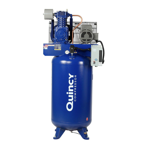
Quincy QR-25 Series User manual

This manual contains important safety information and must be
carefully read in its entirety and understood prior to installation
byallpersonnelwhoinstall,operateand/ormaintainthisproduct.
On-line product registration, parts ordering and warranty information is available at www.quincycompressor.com
Manual No. 50215-106
January 2014 Edition
QR-25
®
Series
Model 325
Parts Manual
Record of Change 106

QR 325 Quincy Compressor
50215-106, January 2014 1 3501 Wismann Lane, Quincy IL - 62305-3116
INTRODUCTION
This manual provides information for the following
QR-25 Series, Model 325 (Record of Change 106)
compressor versions:
L Control Version L
head assembly with 1 unloader tower &
a hydraulic unloader
LS Control Version LS
head assembly with 2 unloader towers, a
hydraulic unloader, & a pilot valve with
a check valve assembly
LVD Control Version LVD
head assembly with 2 unloader towers, a
hydraulic unloader, & a pilot valve with
a lockout & check valve
These compressors are aircooled, two stage, two
cylinder, pressure lubricated compressors, with up
to 200 PSI continuous pressure capability (201 to
500 PSI intermittant pressure capability with proper
configuration; consult factory). The Model 325 has a
4.5" low pressure piston bore and a 2.5" high pres-
sure piston bore and a 3" stroke and can be run at
400-900 RPM.
Available options included in this manual:
-high pressure rated cylinder and head
-spin-on oil filter
-hooded air filter
-hooded air filter / silencer
CHANGES
since previous printing dated October 2006:
Control groups were redesigned.
TABLE OF CONTENTS
..................................2
.................................2
.................................................2
..............................2
................................................3-4
.................................................5-6
......................................................7-8
....................................................9-10
...............................................11-12
................................................13-14
.........................................15-16
............................17-18
.........................................19-20
............................21-22
............................................................23
..........................................................24
.......................................................25
............................................................26
...................................26
...................27
.............................................................28
.........................................................................28
.................................29
....................................................................29
.........................30-32
QR 325 Quincy Compressor
50215-106, January 2014 2 3501 Wismann Lane, Quincy IL - 62305-3116
SERIAL NUMBER
IDENTIFICATION
Model & Serial Number
Identification Tag
The model & serial number tag is located on the
handhole plate side of the crankcase. Fill in the num-
bers from your compressor's tag in the corresponding
spaces provided here and reference this page when
ordering replacement parts.
All replacement parts are to be ordered through
an authorized Quincy distributor. Insist on genuine
Quincy parts only! Failure to do so may void warranty.
ORDERING
Prompt service can be rendered on repair parts orders
if the following information is given:
Item 1) the model number, record of change
number, & serial number.
Item 2) the exact part number needed. (Do not
order by item numbers.)
Item 3) the exact quantity needed.
Item 4) the preferred type of transportation CAUTION !
DANGER !
WARNING !
CRANKCASE LUBRICANT
CAUTION !
Model Less Filter With Filter
325 1 qt. & 16 oz. Add 10 oz.
(1.42 lit.) (296 ml)
Refer to the chart below to order Quin-Cip-D or Quin-
Cip compressor lubricant from your local authorized
Quincy distributor.
Quart 115468Q
Case (12 Qts.) 115438C
Quart 112541Q032
Case (12 Qts.) 112541C032
Quart 112542Q068
Case (12 Qts.) 112542C068
Quart 112543Q100
Case (12 Qts.) 112543C100
Quart 2024601401
Case (12 Qts.) 2024601405

QR 325 Quincy Compressor
50215-106, January 2014 3 3501 Wismann Lane, Quincy IL - 62305-3116
1.2
1.5
1.3
1.4
1.3
1.6
1.1
2
3.1
3.2
3.3
CRANKSHAFT GROUP 110238
3.4

QR 325 Quincy Compressor
50215-106, January 2014 4 3501 Wismann Lane, Quincy IL - 62305-3116
CRANKSHAFT GROUP 110238
Item Part
Number Qty. Number Description
1 1 110217 crankshaft assembly
1.1 1 110216 crankshaft (N.S.S.; order 110217)
1.2 1 110234 orifice, 1/8 npt
1.3 2 2755S pipe plug, 1/8 npt
1.4 1 2585 bearing cone
1.5 1 2788 bearing cone
1.6 1 110705-F15 pin
2 1 1466 key
3 1 110472X sheave assembly
3.1 1 4126R sheave, 16", 2 groove, B sect., ccw (N.S.S.; order 110472X)
3.2 2 110983-N23 hex. screw, 1/2-13 unc x 3.50, grade 8 (@ 90 ft.-lbs.)
3.3 2 116124-N02 square nut, 1/2-13 unc
3.4 2 110428N050 flatwasher
N.S.S. = Not Sold Separate
@ Indicates torque value in foot pounds (dry threads)
Note: For reversal of compressor rotation refer to QR-25 instruction manual.

QR 325 Quincy Compressor
50215-106, January 2014 5 3501 Wismann Lane, Quincy IL - 62305-3116
CRANKCASE GROUP 110237

QR 325 Quincy Compressor
50215-106, January 2014 6 3501 Wismann Lane, Quincy IL - 62305-3116
CRANKCASE GROUP 110237
Item Part
Number Qty. Number Description
1 1 5503X003 crankcase assembly
1.1 1 5503-003 crankcase
1.2 1 2720 bearing cup
2 * 6294D bearing adj. shim, .002 steel
3 * 6294 bearing adj. shim, .005 steel
4 * 6294A bearing adj. shim, .007 steel
5 * 6294B bearing adj. shim, .020 steel
6 * 6294C bearing adj. shim, .005 paper
7 4 123478-L10 hex. screw, 3/8-16 unc x .75, grade 5 (@ 30 ft.-lbs.)
8 1 5506X1 bearing adjustment plate assembly
8.1 1 5506 adjustment plate
8.2 1 6316 oil seal
9 1 112031X001 breather assembly
9.1 1 112032-001 breather tube
9.2 1 5783-002 breather ball
9.3 1 110705-C11 roll pin, 3/32 x .81
9.4 1 112031-001 breather body
10 3 ft. 110515-031 copper tube, 5/16 o.d.
11 1 1301 pipe plug, 3/8 npt
12 1 6272 screen
13 1 6313 gasket, inlet screw
14 1 123157-116 "o"ring, 3/32 wide x .94 o.d.
15 1 6275 gasket, inlet screw
16 1 6273 inlet screw
17 1 1840 gasket, inspection plate
18 1 2322-1 inspection plate, oil filler type
19 6 123478-K12 hex. screw, 5/16-18 unc x 1.00, grade 5 (@ 12 ft.-lbs.)
20 1 110070-3 oil gauge
21 1 8270 inlet tube
22 1 123157-112 "o"ring, 3/32 wide x .69 o.d.
23 1 110919-010 tube fitting, 5/16 tube x 3/8 npt, 90°
8.2 1 6316 oil seal
10.1 1 22749-111 "o"ring, 3/32 wide x .62 o.d.
14 1 22749-116 "o"ring, 3/32 wide x .94 o.d.
22 1 22749-112 "o"ring, 3/32 wide x .69 o.d.
Maintenance Parts
Parts for use with diester or phosphate ester synthetic based lubricants
* Quantity as required
@ Indicates torque value (dry threads).
‡ Assemble item 21 into item 16 with Loctite® 609.
‡
‡

QR 325 Quincy Compressor
50215-106, January 2014 7 3501 Wismann Lane, Quincy IL - 62305-3116
BEARING CARRIER GROUP 110816-001
(with oil filter)
1.11
1.12
1.13
1.14
1.15
1.1
2
1.16
1.2
1.3
1.4
1.6
1.7 1.5
1.10
1.9
1.17
5
6
4
3
1.8

QR 325 Quincy Compressor
50215-106, January 2014 8 3501 Wismann Lane, Quincy IL - 62305-3116
Item Part
Number Qty. Number Description
BEARING CARRIER GROUP 110816-001
(with oil filter)
*
*
*
*
1 1 110810-003 bearing carrier assembly (N.S.S.; order 110810X003)
1.1 1 110810 bearing carrier (N.S.S.; order 110810X003)
1 2523 bearing cup
2 160005 bushing
1.2 1 123157-152 "o"ring, 3/32 wide x 3.44 o.d.
1.3 1 123157-112 "o"ring, 3/32 wide x .69 o.d.
1.4 1 160002-002 driveshaft
1.5 1 160075-001 driveshaft key
1.6 1 160003 pump gerotor
1.7 1 6285 retaining ring
1.8 1 110813-001 oil pump housing
1.9 6 123777-J12 hex. screw, 1/4-20 unc x 1.00, grade 5 (@ 6 ft.-lbs.)
1.10 2 2719 pipe plug, 1/4 npt, hex socket
1.11 1 5489 adjustment screw
1.12 1 123157-011 "o"ring, 1/16 wide x .44 o.d.
1.13 1 124369-P02 jamnut, 9/16-18 unf
1.14 1 1160 spring
1.15 1 112857 needle valve
1.16 2 6565 hole plug
1.17 1 2755S pipe plug, 1/8 npt
2 1 6312 gasket, bearing carrier
3 6 123478-L12 hex. screw, 3/8-16 unc x 1.00, grade 5 (@ 30 ft.-lbs.)
4 1 110822 oil pressure gauge
5 1 110825 stud
6 1 110814-001 6 pack of oil filters
160078 Oil Pump Repair Kit
includes "o"rings, driveshaft, key, pump gerotor, & retaining ring
110810X003 Replacement Bearing Carrier Assembly
includes bearing carrier assy., oil filter, stud, & bearing carrier gasket
Maintenance Parts
*
N.S.S. = Not Sold Separate
@ Indicates torque value (dry threads). Tighten multiple bolts, capscrews & hex nuts in a criss-cross or alternating pattern. Bring
each fastener to the recommended torque specification in even increments.
* Can not be used with diester or phosphate ester synthetic lubricants.
§ Install with Teflon®tape.
§
§

QR 325 Quincy Compressor
50215-106, January 2014 9 3501 Wismann Lane, Quincy IL - 62305-3116
BEARING CARRIER GROUP 110816
(less oil filter)
1.11
1.12
1.13
1.14
1.15
1.1
2
1.16
1.2
1.3
1.4
1.5
4
1.7
1.10
1.9
1.8 3
1.6

QR 325 Quincy Compressor
50215-106, January 2014 10 3501 Wismann Lane, Quincy IL - 62305-3116
Item Part
Number Qty. Number Description
BEARING CARRIER GROUP 110816
(less oil filter)
*
*
*
1 1 110810-002 bearing carrier assembly (N.S.S.; order 110810X002)
1.1 1 110810 bearing carrier (N.S.S.; order 110810X003)
1 2523 bearing cup
2 160005 bushing
1.2 1 123157-152 "o"ring, 3/32 wide x 3.44 o.d.
1.3 1 123157-112 "o"ring, 3/32 wide x .69 o.d.
1.4 1 160002-002 driveshaft
1.5 1 160075-001 driveshaft key
1.6 1 160003 pump gerotor
1.7 1 6285 retaining ring
1.8 1 110813 housing
1.9 6 123777-J12 hex. screw, 1/4-20 unc x 1.00, grade 5 (@ 6 ft.-lbs.)
1.10 2 2719 pipe plug, 1/4 npt, hex socket
1.11 1 5489 adjustment screw
1.12 1 123157-011 "o"ring, 1/16 wide x .44 o.d.
1.13 1 124369-P02 jamnut, 9/16-18 unf
1.14 1 1160 spring
1.15 1 112857 needle valve
1.16 2 6565 hole plug
2 1 6312 gasket, bearing carrier
3 6 123478-L12 hex. screw, 3/8-16 unc x 1.00, grade 5 (@ 30 ft.-lbs.)
4 1 110822 oil pressure gauge
160078 Oil Pump Repair Kit
includes "o"rings, driveshaft, key, & retaining ring
110810X002 Replacement Bearing Carrier Assembly
includes "o"rings, driveshaft, key, pump gerotor, & retaining ring
1.2 1 22749-152 "o"ring, 3/32 wide x 3.44 o.d.
1.3 1 22749-112 "o"ring, 3/32 wide x .69 o.d.
1.12 1 22749-011 "o"ring, 1/16 wide x .44 o.d.
160078-001 Oil Pump Repair Kit
includes "o"rings, driveshaft, key, pump gerotor, & retaining ring
Maintenance Parts
Parts for use with diester or phosphate ester synthetic based lubricants
N.N.S. = Not Sold Separate
@ Indicates torque value (dry threads). Tighten multiple bolts, capscrews & hex nuts in a criss-cross or alternating pattern. Bring
each fastener to the recommended torque specification in even increments.
§ Install with Teflon®tape.
§
§

QR 325 Quincy Compressor
50215-106, January 2014 11 3501 Wismann Lane, Quincy IL - 62305-3116
CONNECTING ROD & PISTON GROUP 110248
(high pressure)
SECOND
BOTTOM
THIRD
6
6
6
7
5
7
4
23
2
1.3
1.2
9
1.1
9
1.4
8
Be sure to stagger ring gaps !
Pip mark
or "T"
on top of ring

QR 325 Quincy Compressor
50215-106, January 2014 12 3501 Wismann Lane, Quincy IL - 62305-3116
CONNECTING ROD & PISTON GROUP 110248
(high pressure)
Item Part
Number Qty. Number Description
Maintenance Parts
*
1 1 40201 connecting rod assembly (N.S.S.; order 6442HPX)
1.1 1 6442C- HP rod, connecting (N.S.S.; see maintenance parts)
1.2 1 6443 bushing, connecting rod (N.S.S.; order 6440SR)
1.3 2 3493 connecting rod bolt
1.4 2 1836 washer
2 2 8648 retaining ring
3 1 110190-021 piston pin
4 1 1530-001 piston , high pressure
5 1 111280 oil ring expander
6 3 1652 piston ring
7 2 111281 oil ring rail
8 2 124471-L08 locknut, 3/8-24 unf (@ 35 ft.-lbs.)
9 2 6444 insert, connecting rod (N.S.S.; see maintenance parts)
9 1 6444PR inserts, connecting rod (1 pair, standard size)
9 1 6444-010PR inserts, connecting rod (1 pair, .010 undersize)
1.2 1 6440SR replacement connecting rod bushing
4 1 1530-011 piston, high pressure (.010 oversize)
4 1 1530-021 piston, high pressure (.020 oversize)
1 8161A Piston Ring Set (standard)
includes piston rings, oil ring rails & expander
1 4422-010 Piston Ring Set (.010 oversize, light blue color code)
includes includes piston rings, oil ring rails & expander
1 4422-020 Piston Ring Set (.020 oversize, yellow color code)
includes includes piston rings, oil ring rails & expander
1 1530X001 Piston Assembly, high pressure (standard)
includes ring set, piston pin, retaining rings, & piston
1530X011 Piston Assembly, high pressure (.010 oversize)
includes ring set, piston pin, retaining rings, & piston
1530X021 Piston Assembly, high pressure (.020 oversize)
includes ring set, piston pin, retaining rings, & piston
6442HPX Replacement Connecting Rod Assembly
includes connecting rod assembly, connecting rod inserts, & locknuts
*
N.S.S. = Not Sold Separate
@ Indicates torque value (dry threads). Tighten multiple bolts, capscrews & hex nuts in a criss-cross or alternating pattern. Bring
each fastener to the recommended torque specification in even increments.
* One pair required for each connecting rod assembly.

QR 325 Quincy Compressor
50215-106, January 2014 13 3501 Wismann Lane, Quincy IL - 62305-3116
CONNECTING ROD & PISTON GROUP 110247
(low pressure)
1.2
2
1.3
4
3
2
5
6
8
1.4
1.1
9
SECOND
7
THIRD
BOTTOM
10
10
5
Be sure to stagger ring gaps !
Pip mark
or "T"
on top of ring

QR 325 Quincy Compressor
50215-106, January 2014 14 3501 Wismann Lane, Quincy IL - 62305-3116
CONNECTING ROD & PISTON GROUP 110247
(low pressure)
Item Part
Number Qty. Number Description
1 1 40139 connecting rod assembly (N.S.S.; see maintenance parts)
1.1 1 6442C rod, connecting (N.S.S.; see maintenance parts)
1.2 1 6443 bushing, connecting rod (N.S.S.; order 6443SR)
1.3 2 3493 connecting rod bolt
1.4 2 1836 washer
2 2 8648 retaining ring
3 1 8646 piston pin
4 1 8643 piston, low pressure
5 2 112781 oil ring expander
6 1 112780 oil ring rail
7 1 7351 piston ring
8 2 124471-L08 locknut, 3/8-24 unf (@ 35 ft.-lbs.)
9 2 6444 insert, connecting rod (N.S.S.; see maintenance parts)
10 2 2584 piston ring
9 1 6444PR inserts, connecting rod (1 pair, standard size)
9 1 6444-010PR inserts, connecting rod (1 pair, .010 undersize)
1.2 1 6443SR replacement connecting rod bushing
4 1 8643-010 piston, low pressure (.010 oversize)
4 1 8643-020 piston, low pressure (.020 oversize)
8166A Piston Ring Set (standard)
includes piston rings, oil ring expander, & rails
4434-010 Piston Ring Set (.010 oversize, light blue color code)
includes piston rings, oil ring expander, & rails
4434-020 Piston Ring Set (.020 oversize, yellow color code)
includes piston rings, oil ring expander, & rails
8643X Piston Assembly, low pressure (standard size)
includes piston, piston pin, retaining rings & ring set
8643X010 Piston Assembly, low pressure (.010 oversize)
includes piston, piston pin, retaining rings & ring set
8643X020 Piston Assembly, low pressure (.020 oversize)
includes piston, piston pin, retaining rings & ring set
6442X Replacement Connecting Rod Assembly (standard)
includes connecting rod assy., connecting rod inserts, & locknuts
Maintenance Parts
*
*
N.S.S. = Not Sold Separate
@ Indicates torque value (dry threads). Tighten multiple bolts, capscrews & hex nuts in a criss-cross or alternating pattern. Bring
each fastener to the recommended torque specification in even increments.
* One pair required for each connecting rod assembly.

QR 325 Quincy Compressor
50215-106, January 2014 15 3501 Wismann Lane, Quincy IL - 62305-3116
CYLINDER & HEAD GROUP 112071
(control version L)

QR 325 Quincy Compressor
50215-106, January 2014 16 3501 Wismann Lane, Quincy IL - 62305-3116
CYLINDER & HEAD GROUP 112071
(control version L)
Item Part
Number Qty. Number Description
1 1 6610-5 cylinder
2 1 1833 gasket, cylinder to crankcase
3 1 7000 gasket
4 1 111496U head assembly (see page 23 for parts breakdown)
5 1 112073 intercooler (N.S.S.; order Intercooler Replacement Kit)
6 1 123478-L10 hex. screw, 3/8-16 unc x .75, grade 5 (@ 30 ft.-lbs.)
7 1 6293-002 clamp
8 7 123115-06C lockwasher, 3/8
9 2 124393-025 fitting
10 2 3092 pipe elbow, 3/4 npt x 3/4 npt, 90°
11 2 90386-N15 counterbore screw, 1/2-13 unc x 1.50, grade 8 (@ 50 ft.-lbs.)
12 4 90386-N20 counterbore screw, 1/2-13 unc x 2.75, grade 8 (@ 50 ft.-lbs.)
13 6 123478-L14 hex. screw, 3/8-16 unc x 1.25, grade 5 (@ 30 ft.-lbs.)
14 1 110377F100 air filter
14 1 110377H100 filter
14 1 110377S100 air filter/silencer, hooded
15 1 110377E100 air filter element, (fits110377F100 & 110377S100 filter)
1 111496X11L Replacement Head Assembly
includes head assy., head gasket, copper tube & fittings
1 111496-051 Replacement Head Assembly (for high pressure rated compressors)
includes high pressure rated head assy., head gasket, copper tube & fittings
1 112088 Intercooler Replacement Kit
includes intercooler and nut / sleeve fittings
N.S.S. = Not Sold Separate
@ Indicates torque value (dry threads). Tighten multiple bolts, capscrews & hex nuts in a criss-cross or alternating pattern. Bring
each fastener to the recommended torque specification in even increments.
* High pressure compressors and DNV certified applications require 111496HPS head in lieu of 111496 head and 6610-5HPS cylin-
der in lieu of 6610-5 cylinder
Maintenance Parts
*

QR 325 Quincy Compressor
50215-106, January 2014 17 3501 Wismann Lane, Quincy IL - 62305-3116
CYLINDER & HEAD GROUP 112072
(control versions LS & LVD)

QR 325 Quincy Compressor
50215-106, January 2014 18 3501 Wismann Lane, Quincy IL - 62305-3116
CYLINDER & HEAD GROUP 112072
(control versions LS & LVD)
Item Part
Number Qty. Number Description
1 1 6610-5 cylinder
2 1 1833 gasket, cylinder to crankcase
3 1 7000 gasket
4 1 111496UU head assembly (see page 25 for parts breakdown)
5 1 112073 intercooler (N.S.S.; order Intercooler Replacement Kit)
6 1 123478-L10 hex. screw, 3/8-16 unc x .75, grade 5 (@ 30 ft.-lbs.)
7 1 6293-002 clamp
8 7 123115-06C lockwasher, 3/8
9 2 124393-025 fitting
10 2 3092 pipe elbow, 3/4 npt x 3/4 npt, 90°
11 2 90386-N15 counterbore screw, 1/2-13 unc x 1.50, grade 8 (@ 50 ft.-lbs.)
12 4 90386-N20 counterbore screw, 1/2-13 unc x 2.75, grade 8 (@ 50 ft.-lbs.)
13 6 123478-L14 hex. screw, 3/8-16 unc x 1.25, grade 5 (@ 30 ft.-lbs.)
14 1 110377F100 air filter
or
14 1 110377H100 filter
or
14 1 110377S100 air filter/silencer, hooded
15 1 3003 pipe tee, 1/4 npt x 1/4 npt x 1/4 npt
16 1 2706 connector
17 1 2708 tube fitting, 90° male elbow, 1/4 tube x 1/4 npt
18 1 110377E100 air filter element, (fits110377F100 & 110377S100 filter)
1 111496X11S Replacement Head Assembly
includes head assy., head gasket, copper tube & fittings
1 111496-052 Replacement Head Assembly (for high pressure rated compressors)
includes high pressure rated head assy., head gasket, copper tube & fittings
1 112088 Intercooler Replacement Kit
includes intercooler and nut / sleeve fittings
Maintenance Parts
N.S.S. = Not Sold Separate
@ Indicates torque value (dry threads). Tighten multiple bolts, capscrews & hex nuts in a criss-cross or alternating pattern. Bring
each fastener to the recommended torque specification in even increments.
* High pressure compressors and DNV certified applications require 111496HPS head in lieu of 111496 head and 6610-5HPS cylin-
der in lieu of 6610-5 cylinder
*

QR 325 Quincy Compressor
50215-106, January 2014 19 3501 Wismann Lane, Quincy IL - 62305-3116
HEAD ASSEMBLY 111496U
(control version L)
Other manuals for QR-25 Series
3
This manual suits for next models
1
Table of contents
Other Quincy Compressor manuals
Popular Compressor manuals by other brands

CICOGNANI ENGINEERING
CICOGNANI ENGINEERING Florence user manual

Gardner Denver
Gardner Denver DRUM D9000 Installation operating & maintenance manual

Drawmer
Drawmer DL241 Operator's manual

SECOP
SECOP P Series Mounting instructions

Powerex
Powerex SLAE03E Service and maintenance manual

WilTec
WilTec AS06 Operation instructions