Package Contents
Quoizel, Inc.
6 Corporate Parkway
Goose Creek, SC 29445
Customer Service
Phone 631.273.2700
Fax 631.231.7102
www.quoizel.com
ToolsRequired:Flathead screwdriver,Phillips screwdriver,pliers, wirecutters, wirestrippers, electricaltape,
safetyglasses.
BulbRecommended: (3) CandelabraBase 60WMaximum,Alternatebulb(3) 13WCFL
EstimatedAssemblyTime:
Preparation:
Fixturecan onlybe mountedin thedirection indicatedon page2.
30-45minutes
Identifyand inspectall partsbefore beginninginstallation. Checkpackage contentlist anddiagrams
belowto besure allparts arepresent. Ifany partsare missingor damaged,do notattempt toassemble, install,or
operatethe fixture.Contact customerservice forreplacement parts.
Warnings and Cautions
1of2
Assembly Instruction Sheet #IS-MBH8409PN
For Style MBH8409PN
Thank you for purchasing a Quoizel product.
Need assistance with parts or assembly? Call Quoizel customer service at 1-631-273-2700
or visit us on-line at www.quoizel.com
2014 QuoizelInc. February2014
Turn off electricity at circuit breaker or main fuse box before installation. Consult a licensed electrician if in doubt.
These instructions are provided for your safety. It is very important you read them completely before installing the fixture. We strongly
recommend that a licensed, professional electrician perform the installation.
Disconnect fixture from power source before replacing bulbs. Make sure bulbs are given sufficient time to cool before removal. Do not subject
glass parts to any shock while in operation or shattering may result.
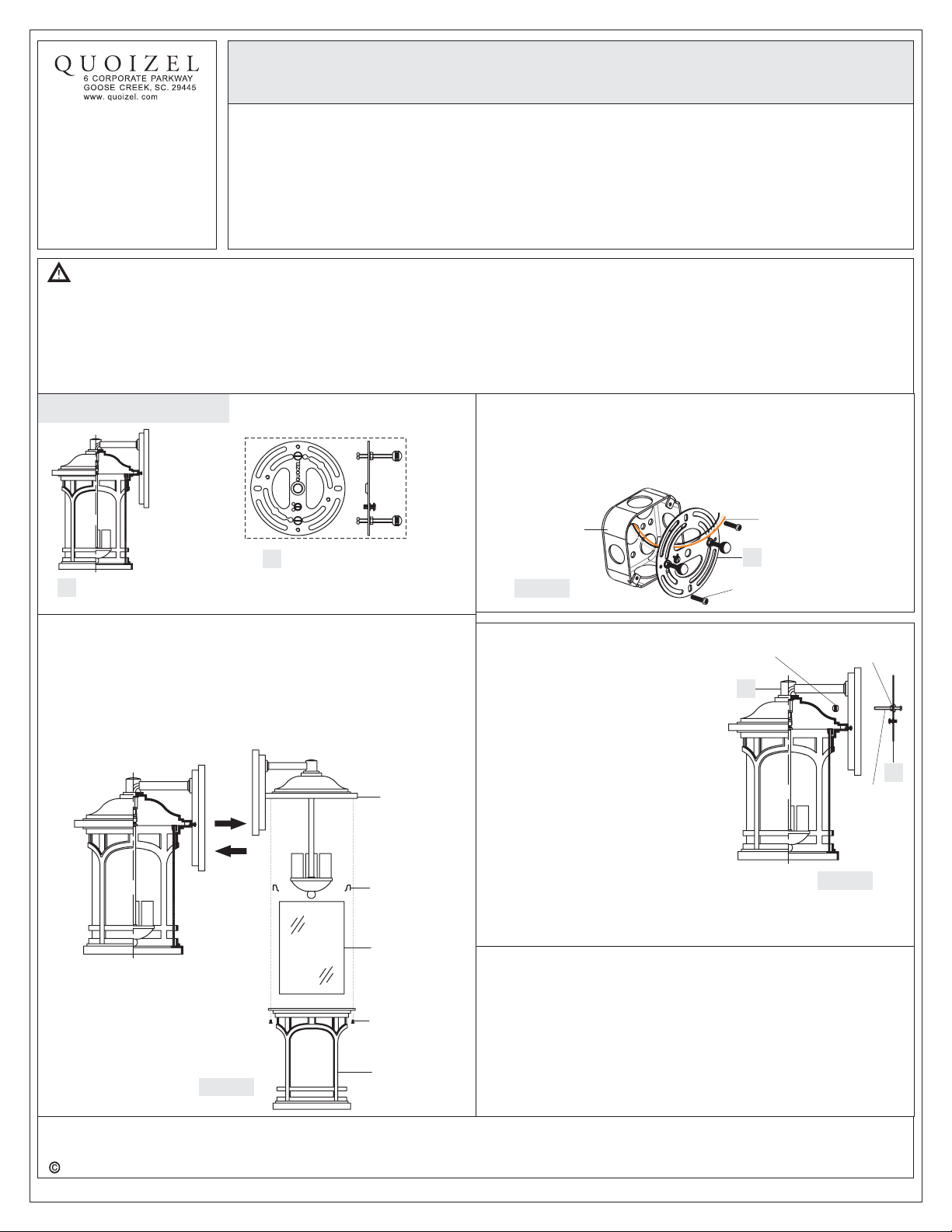
STEP 1 Install Shade-
B. Place Glass Shade into the Cage, secure by place the Tab into the
Cage press on the Glass Shade.
C. Set the Cage with Glass Shade into the Cap on the Fixture Body (A),
secure by threading the Lock Screw into the Cap, tighten until sung.
A. Unscrew the Lock Screw, remove the Cage, the Glass Shade and the
Tab from the Fixture Body (A). Remove the Styrofoam from inside of
the shade.
Figure 3
Figure 1
Mounting
Ball
Mounting
Screw
Hex Nut and
Lock Washer
STEP 2 Install Inner Backplate-
A. Pass the supply wires through the Crossbar Assembly (AA). Attach
the Crossbar Assembly (AA) to the Outlet Box with the head of the
Green Ground Screw facing you. Secure it with Outlet Box Screws
(not included). Tighten until snug.
Supply Wires with
Ground Wire
B
Outlet Box Screws
(not included)
Outlet Box
Figure 2
STEP 3 Fit Fixture Body to
Crossbar Assembly
-
A. Remove mounting balls from the
Crossbar Assembly (B). Fit the
Fixture Body (A) Crossbar
Assembly (B) and secure with
mounting balls. Note: The
backplate of the Fixture Body (A)
should be snug against the wall
surface and the mounting balls. If
not, adjust the length of the nipple
on the Crossbar Assembly (B) by
unscrewing the preassembled hex
nut and lock washer and then
screwing the mounting screws in or
out of the crossbar until the correct
length is achieved. Once the
backplate of the Fixture Body (A) is
secure, remove the mounting ball
and Fixture Body (A) and proceed
to Step 4.
STEP 4 - Wire Connections
A. Use standard wire connectors (not included) to make all wire
connections. (Connectors are not included with fixture.) Strip and
prepare wire ends according to instructions supplied with
connectors.
B. Connect White Supply Wire from the Outlet Box to Ribbed side Wire
from fixture.
C. Connect Black (or Red) Supply Wire from the Outlet Box to Smooth
side Wire from fixture.
D. Connect Ground Wire from the Outlet Box to Ground Wire from
B
A
BCrossbar Assembly
x1
Fixture Body
x1
A
Fixture Body
Cage
Tab
Glass Shade
Lock Screw


