r.LiNK CI-RL2-MMI3G-GW-VW User manual

Version 09.08.2021 HW CAM(V31),(V22) CI-RL2-MMI3G-GW/Q3
Video-inserter
RL2-MMI3G-GW/Q3
Compatible with
Audi vehicles with
MMI3G basic/high, MMI3G+ basic/high infotainments
VW vehicles with
RNS850 infotainment and 4pin HSD LVDS connector
Video-inserter for rear-view camera
and two additional video sources
Product features
Video-inserter for factory-infotainment systems
2 CVBS video-inputs for after-market devices (e.g. DVD-Player, DVB-T tuner)
CVBS Rear-view camera video-input
Automatic switching to rear-view camera input on engagement of reverse gear
Activatable parking guide lines for rear-view camera (not available for all vehicles)
Video-in-motion (ONLY for connected video-sources)
Video-inputs PAL/NTSC compatible

Version 09.08.2021 HW CAM(V31),(V22) CI-RL2-MMI3G-GW/Q3
Seite2
Contents
1. Prior to installation
1.1. …Delivery contents
1.2. Checking the compatibility of vehicle and accessories
1.3. Boxes and connectors
1.3.1. CAN-bus box
1.3.2. Video-interface
1.4. Dip-switch settings –video interface (8 dip black)
1.4.1. …Enabling the interface’s video inputs (dip 2-3)
1.4.2. Rear-view camera setting (dip 5)
1.4.3. Monitor selection (dip 7-8)
1.5. Dip-switch settings –CAN box 4dip –red)
2. Installation
2.1. Place of installation
2.2. Connection schema
2.3. Connection - video-interface and CAN-box
2.4. Connection - head-unit
2.5. Connection to the CAN-gateway (not for Q3 and RNS850)
2.6. Special case Audi Q3 - 4pin harness with stripped cable ends
2.7. Special case RNS-850 –stripped 4pin harness
2.8. Connection –video sources´
2.8.1. Audio-insertion
2.8.2. After-market rear-view camera
2.8.2.1. Case 1: CAN-box detects reverse gear
2.8.2.2. Case 2: CAN-box does not detect reverse gear
2.9. Connection video-interface and keypad
2.10. Picture settings and guide lines
3. Interface operation
3.1. By infotainment key
3.2. By keypad
4. Specifications video-interface
5. Frequently asked questions

Version 09.08.2021 HW CAM(V31),(V22) CI-RL2-MMI3G-GW/Q3
Seite3
Legal Information
By law, watching moving pictures while driving is prohibited, the driver must not be
distracted. We do not accept any liability for material damage or personal injury resulting,
directly or indirectly, from installation or operation of this product. This product should only
be used while standing or to display fixed menus or rear-view-camera video when the
vehicle is moving, for example the MP3 menu for DVD upgrades.
Changes/updates of the vehicle’s software can cause malfunctions of the interface. If
available, we offer free software-updates for our interfaces for one year after purchase. To
receive a free update, the interface must be sent in at own cost. Labor cost for and other
expenses involved with the software-updates will not be refunded.
1. Prior to installation
Read the manual prior to installation.
Technical knowledge is necessary for installation. The place of installation must be free of
moisture and away from heat sources.
1.1. Delivery contents
Take down the serial number of the interface and store this manual for support
purposes: ____________________

Version 09.08.2021 HW CAM(V31),(V22) CI-RL2-MMI3G-GW/Q3
Seite4
Requirements
Brand
Vehicles
Infotainment
Audi
A1 (8X) since 05/2010 til 10/2018
A4 (8K) since 05/2009 til 08/2015
A5 (8T) since 11/2008 til 06/2016
A6 (4F) since 08/2008 til 03/2011
A6 (4G) since 04/2011 til 09/2014
A7 (4G) since 07/2010 til 05/2014
A8 (4E) since 09/2008 til 03/2010
A8 (4H) since 03/2010 til 10/2017
Q3 (8U) 10/2011 –07/2018
Q5 (8R) since 11/2008 til 2017
Q7 (4L) since 05/2009 til 03/2015
MMI Navigation (Plus) -
MMI3G+, MMI3G High,
MMI3G Basic –
7inch or 8inch monitor
A1 (8X) since 05/2010
A6 (4F) since 08/2008 til 03/2011
A6 (4G) since 04/2011 til 05/2018
A7 (4G) since 07/2010 til 01/2018
Q3 (8U) 10/2011 –07/2018
Q7 (4L) since 05/2009 til 03/2015
MMI Radio/MMI Radio
Plus/MMI Navigation -
RMC/RMC_Cnct_Plus/
RMC_Cnct_Nav –
6.5inch monitor
VW
Touareg (7P) since model year 2011 til 06/2018
RNS850
Limitations
Video only The interface inserts ONLY video into the infotainment.
For sound use the possibly existing factory-audio-AUX-input, a
FM-modulator or the AUX-in interface AUX-110.
Factory OPS Display of an optical park display (OPS) isn’t possible if an
after-market rear-view camera is connected and reverse gear is
engaged. Acoustic signals are still existing.
Guide lines If the video interface does not receive the required information
from the vehicle CAN-bus, guide lines will not be supported.
Factory rear-view camera Automatic switch-back from inserted video to factory rear-view
camera only while reverse gear is engaged. To delay the switch-
back time, additional electronics is required.
1.2. Checking the compatibility of vehicle and accessories

Version 09.08.2021 HW CAM(V31),(V22) CI-RL2-MMI3G-GW/Q3
Seite5
1.3. Boxes and connectors
1.3.1. CAN-bus box
The CAN-bus box reads digital signals from the vehicle’s CAN-bus and converts them for the
video-interface.
1.3.2. Video-interface
The video-interface converts the video signals of connected after-market sources in a factory
monitor compatible picture signal which is inserted in the factory monitor, by using separate
trigger options. Further it reads the vehicle’s digital signals out of the vehicle’s CAN-bus and
converts them for the video interface.

Version 09.08.2021 HW CAM(V31),(V22) CI-RL2-MMI3G-GW/Q3
Seite6
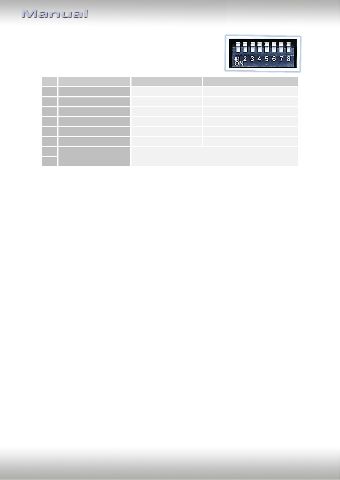
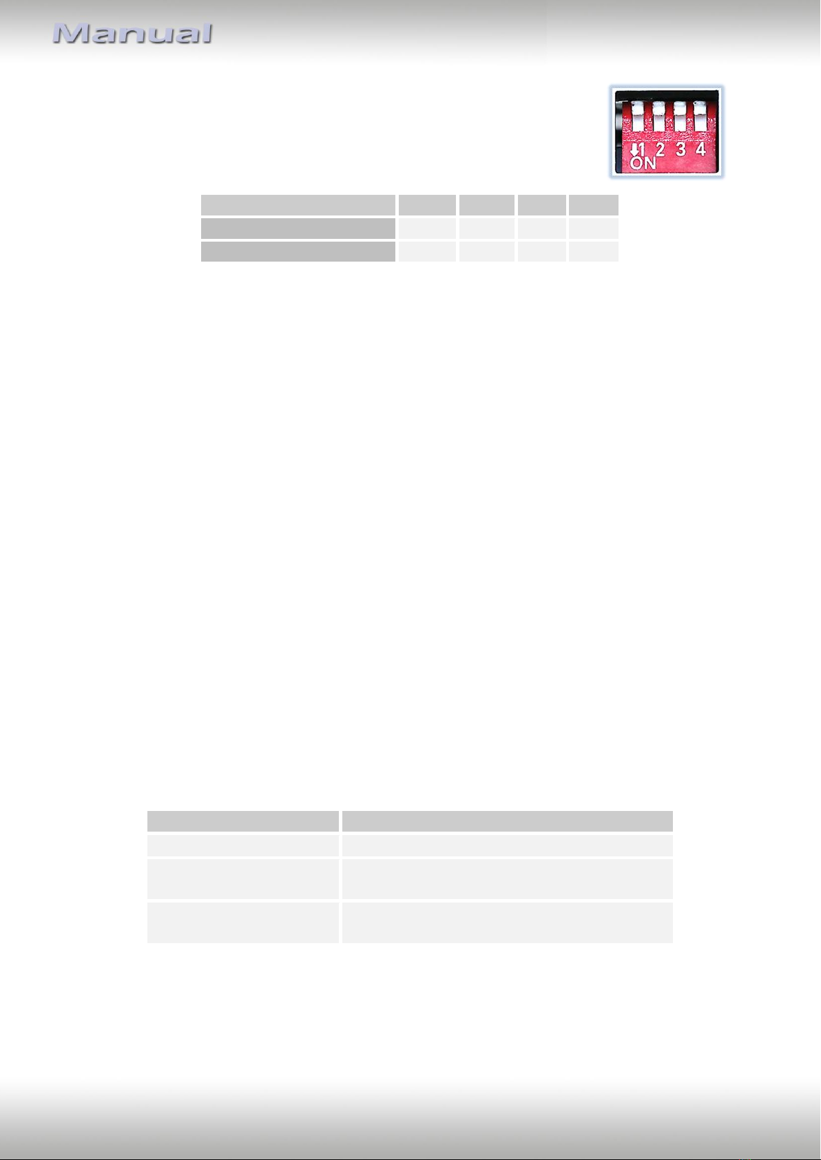
1.4. Dip-switch settings - video interface(8dip –black)
Some settings must be selected by the dip-switches on the
video interface. Dip position down is ON and position up is OFF.
See following chapters for detailed information.
1.4.1. Enabling the interface’s video inputs (dip 2-3)
Only the enabled video inputs can be accessed when switching through the interface’s video
sources. It is recommended to enable only the required inputs for the disabled will be
skipped when switching through the video interfaces inputs.
1.4.2. Rear-view camera setting (dip 5)
If set to OFF, the interface switches to factory LVDS picture while the reverse gear is engaged
to display factory rear-view camera or factory optical park system picture.
If set to ON, the interface witches to its rear-view camera input CAM while the reverse gear
is engaged.
1.4.3. Monitor selection (dip 7-8)
Dips 7 and 8 customize the monitor-specific video settings which sometimes even vary
within head units of the same version, caused by different monitor specifications. It is
necessary to try all possible combinations of the 3 dips while a working video source is
connected to the chosen input of the interface. One of the combinations will show the best
picture size and quality (some may give no picture). It is possible to first hot plug through the
dip combinations. If there is no visible change of picture after trying all options, retry and
disconnect the 6pin plug of the video interface between every change of the dip setting.
Dip 1, 4 and 6 are out of function and have to be set to OFF.
After each Dip-switch-change a power-reset of the Video Interface has to be performed!
Dip
Function
ON (down)
OFF (up)
1
No function
-
set to OFF
2
CVBS AV1-input
enabled
disabled
3
CVBS AV2-input
enabled
disabled
4
No function
-
set to OFF
5
Rear-view cam type
after-market
factory or none
6
No function
set to OFF
7
Monitor specific
adjustments
Try all possible combinations of Dips 7 and 8 to receive
the best picture (quality and size)
8

Version 09.08.2021 HW CAM(V31),(V22) CI-RL2-MMI3G-GW/Q3
Seite7
1.5. Dip-Schalter Einstellungen –CAN box (4dip –red)
Choose the navigation the interface is to be installed in and set dip 1 to 4
according to the below table.
vehicle/infotainment
Dip 1
Dip 2
Dip 3
Dip 4
A1, A4, Q3
OFF
OFF
OFF
OFF
A6, Q7
ON
OFF
OFF
OFF
Note: The experience values of the CAN bus dip settings are only exemplary. If the Can
communication doesn’t succeed, try other dip combinations.
After each Dip-switch-change a power-reset of the Video Interface has to be performed!
2. Installation
To install the interface, first switch off the ignition and disconnect the vehicle’s battery.
Please read the owner`s manual of the car, regarding the battery`s disconnection! If
required, enable the car`s Sleep-mode (hibernation mode)
In case the sleep-mode does not succeed, the disconnection of the battery can be done
with a resistor lead.
If the necessary stabilized power supply for the interface is not taken directly from the
battery, the chosen connection has to be checked for being constantly stabile.
The interface needs a permanent 12V source!
2.1. Place of installation
The interface shell be installed on the backside of the head-unit
(navigation computer/radio).
Depending on the interface version the connection to CAN-Bus and power is different:
Item no.
PNP cable CAN-bus/power
All vehicles
CAN-gateway
Special case RNS850:
RL2-MMI3G-GW
Cable with stripped ends
Climate control panel
Special case Audi A3 (Q8)
Cable with stripped ends
Climate control panel and Quadlock connector

Version 09.08.2021 HW CAM(V31),(V22) CI-RL2-MMI3G-GW/Q3
Seite8
2.2. Connection scheme

Version 09.08.2021 HW CAM(V31),(V22) CI-RL2-MMI3G-GW/Q3
Seite9
2.3. Connection - video-interface and CAN-box
The CAN-bus box reads digital signals from the CAN-bus and converts them for the video-
interface. ACC +12V max. 0.5A (red of 6pin) and reverse gear +12V max. 0.5A (green of 6pin)
constant signal. Video-source switching (white of 6pin) as +12V impulse.
Connect theblack female 4pin connector of the 20pin PNP harness to the male 4pin
connector of the CAN-box.
Connect the white female 6pin connector of the 6pin to 8pin cable to the male 6pin
connector of the video-interface.
Connect the black female 8pin connector of the 6pin to 8pin cable to the male 8pin
connector of the CAN-box.
Connect the CAN communication cable’s white female 8pin connector to the 8pin
connector of the video interface.
Connect the separate white cable to the MMI signal at pin10 of the Quadlock for
alternative switching of sources by NAV button in the centre console, if existing.
(Only for MMI 3G, not for MMI 3G+ or RNS850)

Version 09.08.2021 HW CAM(V31),(V22) CI-RL2-MMI3G-GW/Q3
Seite10
Note: Check the LEDs on CAN-box after reconnecting the battery, two must be on.
Not all vehicles are kompatible. If the CAN-box does not deliver ACC to pin2 of the video-
interface or blocks the thevehicle’s CAN, it is possible to install the video interface without
the CAN-box (analog). In this case see also note in chapter “After-market rear-view
camera”. For analogue connection see 6pin assignment above.
2.4. Connection –head unit
Remove the grey (Depending on the head-unit, possibly also white or pink coloured!)
female 4pin HSD connector from the rearside of the factory head unit and connect it
to the aubergine colored male 4pin HSD connector of the picture signal cable.
Connect the waterblue colored female 4pin HSD connector of the picture signal cable
to the previously become free grey (Depending on the head-unit, possibly also white
or pink coloured!) male 4pin HSD connector of the factory head-unit.
Connect the waterblue colored female HSD+2 connector of the picture signal cable
to the male HSD+2 connector of the video-interface.
Note: No liability for vehicle wire colours and pin definition!
Changes by the vehicle manufacturer are possible. The given information has to be verified
by the installer.

Version 09.08.2021 HW CAM(V31),(V22) CI-RL2-MMI3G-GW/Q3
Seite11
2.5. Connection to the CAN-gateway (not for Q3 and RNS850)
Set the Gateway free.
Location of CAN-gateway
• A1/A3 below the steering-wheel
• A6/A7/A8 footwell passenger side below right
(A6 from 2013 middle of rear bench seat)
• Q5 footwell on the passenger side top left
• A5 (8T) on the left side behind the glove compartment.
Disconnect the female 20pin connector of the factory harness at the
CAN Gateway and connect it to the 20pin connector of the 20-Pin PNP harness.
Connect the opposite female 20pin connector of that 20pin PNP harness
to the previously become free 20-Pin connector of the CAN Gateway.
Note: In case of difficulties with the connection of the 20pin PNP
harness; the enclosed stripped 4pin harness can be used for the
upper shown Gateway pin connection.
Pin diagram
4pin cable
Pin diagram
CAN-gateway
• CAN Low grey
Generally:
••Pin 5 orange/grey
(Audi A6 with deviant connector:
••Pin 6 orange/brown)
• CAN High blue
Generally:
••Pin 15 orange/green
(Audi A6 with deviant connector:
••Pin 22 orange/blue (Audi A6)

Version 09.08.2021 HW CAM(V31),(V22) CI-RL2-MMI3G-GW/Q3
Seite12
2.6. Special case Audi Q3 - 4pin harness with stripped cable ends
Connect the blue coloured wire CAN HIGH and the grey coloured wire CAN Low of
the enclosed 4pin cable with stripped ends to the according pins of the climate
control panel’s 16pin connector, like shown in the upper diagram.
Connect the red and the brown wire, according to the diagrams above, to the female
40-pin- or 52pin Quadlock connector of the factory harness.

Version 09.08.2021 HW CAM(V31),(V22) CI-RL2-MMI3G-GW/Q3
Seite13
2.7. Special case RNS850 - 4pin harness with stripped cable ends
For installation in VW vehicles with RNS850 use the additional 4pin power cable with open
ends. The PNP power/CAN cable isn’t needed.
Connect the female 4pin connector of the 4pin harness to the 4pin connector of the
CAN box.
Connect the stripped ends of the 4pin cable to ground, battery +12V, CAN high and
CAN low of the climate control unit harness, without cutting the cables of the
vehicle harness.
The following pin diagram shows pins and cable colours:
There`s no liability for the vehicle`s pin diagram!
Changes in the manufacturer`s production are possible any time. The mentioned
information has to be verified by the installer.
Pin-diagramm
4pin cable
Pin diagram
CAN-gateway
• grey CAN Low
••Pin 3 orange /brown
• blue CAN High
••Pin 2 orange/violett

Version 09.08.2021 HW CAM(V31),(V22) CI-RL2-MMI3G-GW/Q3
Seite14
2.8. Connection –video sources
It is possible to connect 2 after-market Video-sources and 1 after-market rear-view camera
to the video-interface.
Before final installation of the peripheral devices, we recommend a test-run of the
interface. Due to changes in the production of the vehicle manufacturer is always the
possibility of incompatibility.
Connect the female 6pin connector of the video cable to the male 6pin connector of the
video-interface.
Connect the video RCA of the video source 1 and 2 to the female RCA connector
“Video IN1” and ”Video IN 2” of the 6pin video cable.
Connect the video RCA of the rear-view camera to the female RCA connector
“Camera IN” of the 6pin video cable.

Version 09.08.2021 HW CAM(V31),(V22) CI-RL2-MMI3G-GW/Q3
Seite15
2.8.1. Audio insertion
This interface can only insert video signals into the factory infotainment. Audio insertion
must be done by factory audio AUX input, the optionally available AUX-in interface AUX-110
(only for MMI3G, not for MMI3G+) or FM-modulator. The inserted video-signal can be
activated simultaneously to each audio-mode of the factory infotainment.
If 2 AV sources shall be connected to the infotainment, additional electronic is necessary to
switch the audio signals.
2.8.2. After-market rear-view camera
Some vehicles have a different reverse gear code on the CAN-bus which the included CAN-
box is not compatible with. Therefore, there are two different ways of installation. If the
CAN-box detectes the vehicle’s reverse gear, the green wire of the 6pin to 8pin cable should
carry +12V while the reverse gear is engaged.
Note: Do not forget to set dip5 of video-interface to ON before testing.
2.8.2.1. Case 1: CAN-box detects reverse gear
If the CAN-bus interface delivers +12V on the green wire of the 6pin to 8pin cable when
reverse gear is engaged, the video interface will automatically be switched to the rear-view
camera input CAM while reverse gear is engaged.
Additionally, the +12V (max. 500mA) power supply for the rear-view camera can be
taken from the green wire of the 6pin to 8pin cable.

Version 09.08.2021 HW CAM(V31),(V22) CI-RL2-MMI3G-GW/Q3
Seite16
2.8.2.2. Case 2: CAN-box does not detect reverse gear
If the CAN-bus interface does not deliver +12V on the green wire of the 6pin to 8pin cable
when reverse gear is engaged (not all vehicles are compatible) an external switching signal
from the reverse gear light is required. As the reverse gear light signal contains electronic
interference, a normally open relay (e.g AC-RW-1230 with wiring AC-RS5) or filter (e.g. AC-
PNF-RVC) is required. Below schema shows the use of a relay (normally open).
Connect the green wire of the 6pin to 8pin cable to the output connector (87) of the
relay.
Connect the Reverse light’s power-cable to coil (85) and the vehicle’s ground to coil
(86) of the relay.
Connect the output connector (87) of the relay to the rear-view camera’s power-
cable, like you did it to the green wire of the 6pin to 8pin cable before.
Connect stabile and permanent +12V to the relay’s input connector (30).

Version 09.08.2021 HW CAM(V31),(V22) CI-RL2-MMI3G-GW/Q3
Seite17
2.9. Connecting video-interface and keypad
Connect the female 4pin connector of the keypad to the male 4pin connector of the
video-interface.

Version 09.08.2021 HW CAM(V31),(V22) CI-RL2-MMI3G-GW/Q3
Seite18
2.10. Picture settings and guide lines
The picture settings are adjusted by the 3 buttons on the video-interface. Press the MENU
button to open the OSD settings menu or to switch to the next menu item. Press UP and
DOWN will change the selected value. The buttons are embedded in the housing to avoid
accidental changes during or after installation. Picture settings must be done separately for
AV1 and AV2 while the corresponding input is selected and visible on the monitor. The rear-
view camera settings conceivably have to be done in AV 2.
Note: The OSD menu is only shown when a working video source is connected to the
selected video-input of the interface.
The following settings are available:
Contrast
Brightness
Saturation
Position H / V (no function)
IR-AV1/AV2 (no function)
Guide-CNTRL (guide-lines for rear-view camera)
Guide L/R (no function)
PDC CNTRL (ON/OFF) (Factory PDC ON/OFF)
CAR-TYPE (no function)
Note:
To adjust the reverse picture, engage the reverse gear.
To adjust the guide lines, move the steering wheel to see the changes.
If there is no communication between interface and the vehicle`s CAN-bus (several vehicles
aren’t compatible), the reverse gear guide-lines can`t be shown during the vehicle’s
operation, even if they once appear after having switched the system to powerless!

Version 09.08.2021 HW CAM(V31),(V22) CI-RL2-MMI3G-GW/Q3
Seite19
3. Interface operation
3.1. By infotainment-buttons
The NAV button and the MODE button of the MMI are used to execute interface functions.
MMI3G
Longpress (2-3 seconds) of MODE or NAV button
MMI3G+ and Audi A1 vehicles
Longpress (2-3 seconds) of the steering wheel’s NAVI button
Each press will switch to the next enabled input. If all inputs are enabled the order is:
Factory video
video IN1
video IN2
factory video
…
Inputs which are not enabled by dip switch settings are skipped.
Switchover by vehicle buttons isn’t possible in all vehicles. In some vehicles the external
keypad must be used.
Note: Alternatively the white wire of the 6pin cable can be used with a +5-12V pulse to
switch the video-sources.
3.2. By keypad
Alternatively or additionally to the factory infotainment buttons the interface’s external
keypad can be used to switch the enabled inputs.
4. Specifications video-interface
BATT/ACC range 7V - 25V
Stand-by power drain 40mA
Power 240mA
Video input 0.7V - 1V
Video input formats PAL/NTSC
Temperature range -40°C to +85°C
Dimensions video-box (W x H x D) 113 x 22 x 115mm
Dimensions CAN-box (W x H x D) 73 x 22 x 30 mm

Version 09.08.2021 HW CAM(V31),(V22) CI-RL2-MMI3G-GW/Q3
Seite20
4. FAQ –Trouble shooting Interface functions
For any troubles which may occur, check the following table for a solution before requesting
support from your vendor.
Symptom
Reason
Possible solution
No picture/black
picture (factory
picture).
Not all connectors have been
reconnected to factory head-
unit or monitor after
installation.
Connect missing connectors.
No power on CAN-bus box (all
LED CAN-bus box are off).
Check power supply of CAN-bus box. Check CAN-bus
connection of CAN-bus box.
CAN-bus box connected to
CAN-bus in wrong place.
Refer to the manual where to connected to the CAN-
bus. If not mentioned, try another place to connect to
the CAN-bus.
No power on video-interface
(all LED video-interface are
off).
Check whether CAN-bus box delivers +12V ACC on red
wire output of 8pin to 6pin cable. If not cut wire and
supply ACC +12V directly to video-interface.
No picture/black
picture/white picture
(inserted picture) but
factory picture is OK.
No picture from video source.
Check on other monitor whether video source is OK.
No video-source connected to
the selected interface input.
Check settings dips 1 to 3 of video interface which
inputs are activated and switch to corresponding
input(s).
LVDS cables plugged in wrong
place.
Double-check whether order of LVDS cables is exactly
connected according to manual. Plugging into head-
unit does not work when the manual says to plug into
monitor and vice versa.
Wrong monitor settings of
video-interface.
Try different combinations of dips 7 and 8 of video-
interface. Unplug 6pin power after each change.
Inserted picture totally
wrong size or position.
Inserted picture double
or 4 times on monitor.
Inserted picture
distorted, flickering or
running vertically.
Video sources output set to
AUTO or MULTI which causes
a conflict with the interfaces
auto detection.
Set video source output fixed to PAL or NTSC. It is best
to set all video sources to the same standard.
If error occurs only after
source switching: Connected
sources are not set to the
same TV standard.
Set all video sources to the same standard.
Some interfaces can only
handle NTSC input.
Check manual whether there is a limitation to NTSC
mentioned. If yes, set source fixed to NTSC output.
Inserted picture b/w.
Inserted picture qual.
bad.
Picture settings have not been
adjusted.
Use the 3 buttons and the interface's OSD to adjust the
picture settings for the corresponding video input.
Inserted picture size
slightly wrong.
Inserted picture
position wrong.
Camera input picture
flickers.
Camera is being tested under
fluorescent light which shines
directly into the camera.
Test camera under natural light outside the garage.
Camera input picture is
bluish.
Protection sticker not
removed from camera lens.
Remove protection sticker from lens.
This manual suits for next models
1
Table of contents
Other r.LiNK Automobile Accessories manuals