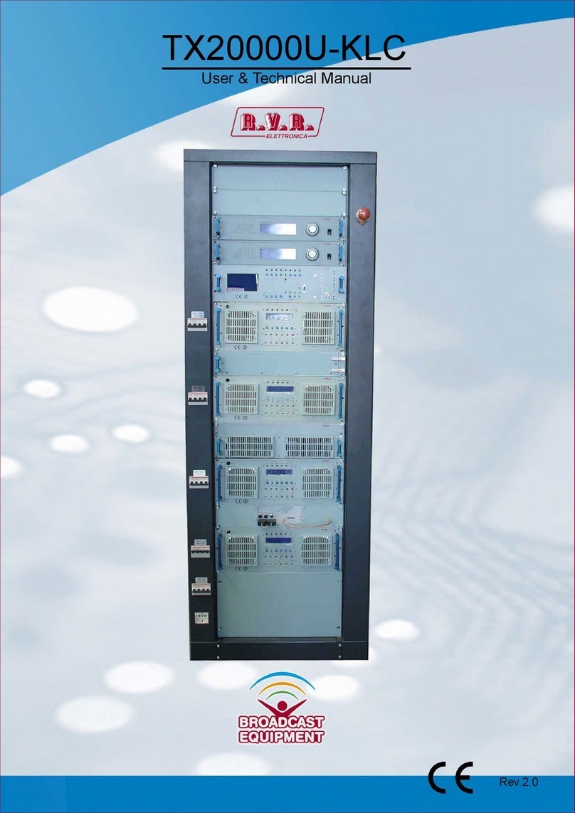
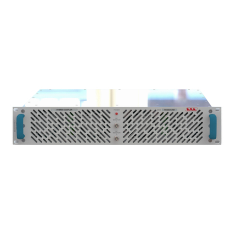
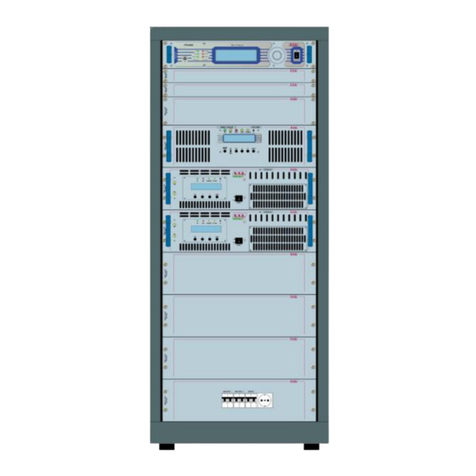
R.V.R. Elettronica PTX-DDS User manual

PTX-DDS
User Manual
Manufactured by Italy

PTX-DDS - User Manual
Versione 1.2
© Copyright 2006-2011
R.V.R. Elettronica SpA
Via del Fonditore 2/2c - 40138 - Bologna (Italia)
Phone: +39 051 6010506
Fax: +39 051 6011104
Email: info@rvr.it
Web: www.rvr.it
All rights reserved
Printed and bound in Italy. No part of this manual may be reproduced,
memorized or transmitted in any form or by any means, electronic
or mechanic, including photocopying, recording or by any informa-
tion storage and retrieval system, without written permission of the
copyright owner.
File Name: 03_PTX-DDS_ING_1.2.indd
Version: 1.2
Date: 24/01/2011
Document History
Date Version Reason Editor
08/05/2006 1.0 First Edition J. H. Berti
29/11/2010 1.1 Major Upgrade J. H. Berti
24/11/2011 1.2 External dip-switch upgrade J. H. Berti

PTX-DDS
iUser Manual Rev. 1.2 - 24/01/11
Table of Contents
1. Preliminary Instructions 1
2. Warranty 1
3. First Aid 2
3.1 Treatment of electrical shocks 2
3.2 Treatment of electrical Burns 2
4. General Description 3
5. Quick guide for installation and use 4
5.1 Preparation 4
5.2 First power-on and setup 6
6. External Description 10
6.1 Front Panel 10
6.2 Rear Panel 11
6.3 Connector Descriprion 12
7. Operating System 13
7.1 Using the encoder 13
7.2 Start-up 14
7.3 Operating System 14
7.4 Menu Organization 16
7.5 Set up Reset 43
7.5 Audio Rescuer 44
7.7 I.T.U. 47
7.8 A.G.C.andClipper 47
8. TechnicalSpecication 49
9. ModulesIdentication 51
9.1 Top View 51
9.2 Power supply unit 52
9.3 Poweramplier 52
9.4 Panel Card 52
9.5 16-bit CPU Card 53
9.6 TRDSP Card 53

PTX-DDS
ii User ManualRev. 1.2 - 24/01/11
This page was intentionally left blank

1 / 54User Manual Rev. 1.2- 24/01/11
PTX-DDS
1. Preliminary Instructions
• General foreword
The equipment in object is to considering for uses,
installation and maintenance from “trained” or “qualied”
staff, they conscious of the risks connected to operate
on electronic and electrical circuits electrical.
The “trained” definition means staff with technical
knowledge about the use of the equipment and with
responsibility regarding the own safety and the other
not qualified staff safety place under his directed
surveillance in case of works on the equipment.
The“qualied”denitionmeansstaffwithinstructionand
experience about the use of the equipment and with
responsibility regarding the own safety and the other not
qualiedstaffsafetyplaceunderhisdirectedsurveillance
in case of works on the equipment.
WARNING: The machine can be equipped with
an ON/OFF switch which could not remove completely
voltages inside the machine. It is necessary to
have disconnected the feeding cord, or to have
switched off the control panel, before to execute
technical operations, making sure himself that the
safety connection to ground is connected.
The technical interventions that expect the equipment
inspection with circuits under voltage must be carry out
fromtrainedand qualied staff in presence of a
second trained person that it is ready to intervene
removing voltage in case of need.
R.V.R. Elettronica SpA doesn’t assume responsibility for
injury or damage resulting from improper procedures or
practicesbyuntrained/unqualiedpersonnelinthehandling
of this unit.
WARNING: The equipment is not water resistant
and an infiltration could seriously compromise
its correct operation. In order to prevent fires or
electric shocks, do not expose the equipment to rain,
inltrationsorhumidity.
Pleaseobservealllocalcodesandreprotectionstandards
during installation and use of this unit.
WARNING: The equipment has to its inside
exposed parts to risk of electric shock, always
disconnect power before opening covers or removing
any part of this unit.
Fissures and holes are supplied for the ventilation in order
toassureareliableefcacyoftheproductthatforprotect
itselffrom excessive heating, these ssures do nothave
tobeobstructedortobecovered.Thessuresdoesn’tbe
obstructed in no case. The product must not be incorporated
in a rack, unless it is supplied with a suitable ventilation or
that the manufacturer’s instructions are been followed.
WIRING: This equipment can irradiate radio
frequency energyand if it’s not installed following
the instructions contained in the manual and local
regulations it could generate interferences in radio
communications.
WIRING: This device has a connection to ground
on the power cord and on the chassis. Check that they
are correctly connected.
Operate with this device in a residential ambient can cause
radio disturbs; in this case, it can be demanded to the user
to take adequate measures.
Specications and informations contained in this manual
are furnished for information only, and are subject to change
at any time without notice, and should not be construed
as a commitment by R.V.R. Elettronica SpA.
The R.V.R. Elettronica SpA assumes no responsability or
liability for any errors or inaccuracies that may appear in
this manual, including the products and software described
in it;and it reserves the right to modify the design and/or
thetechnicalspecicationsoftheproductandthismanual
without notice.
• Warning regarding the use designated and the use
limitations of the product.
This product is an transmitter radio indicated
for the audio broadcasting service in frequency
modulation. It uses working frequencies that are not
harmonized in the states of designated user.
The user of this product must obtain from the Authority
for spectrum management in the state of designated
user the appropriate authorization to use the radio
spectrum, before putting in exercise this equipment.
The working frequency, the transmitter power, let alone
otherspecicationsofthetransmissionsystemaresubject
tolimitationanddenitedintheauthorizationobtained.
2. Warranty
R.V.R. Electronics S.P.A. guarantees absence of
manufacturing defect and the good operation for the
products, within the provided terms and conditions.
Please read the terms carefully, because the purchase of
theproductoracceptanceoforderconrmation,constitutes
acceptance of the terms and conditions.
For the last legal terms and conditions, please visit our web
site (WWW.RVR.IT) wich may also be changed, removed
or updated for any reason without prior notice.
Warranty will be void in cases of opened products, physical
damage, misuse, modification, repair by unauthorised
persons, carelessness and using the product for other
purpose than its intended use.
In case of defect, proceed like described in the following:
1 Contact the dealer or distributor where you purchased
the unit. Describe the problem and, so that a possible
easy solution can be detected.
Dealers and Distributors are supplied with all the information
about problems that may occur and usually they can repair
the unit quicker than what the manufacturer could do. Very
often installing errors are discovered by dealers.
2 If your dealer cannot help you, contact R.V.R. Elettronica
and explain the problem. If it is decided to return the
unit to the factory, R.V.R. Elettronica will mail you a
regular authorization with all the necessary instructions
to send back the goods;
3 When you receive the authorization, you can return the
unit. Pack it carefully for the shipment, preferably using
the original packing and seal the package perfectly.
The customer always assumes the risks of loss (i.e.,
IMPORTANT
The symbol of lightning inside a triangle placed on the product, evidences the operations for
which is necessary gave it full attention to avoid risk of electric shocks.
The symbol of exclamation mark inside a triangle placed on the product, informs the user
about the presence of instructions inside the manual that accompanies the equipment, im-
portantfortheefcacyandthemaintenance(repairs).

2 / 54 User ManualRev. 1.2 - 24/01/11
PTX-DDS
R.V.R. is never responsible for damage or loss), until
the package reaches R.V.R. premises. For this reason,
we suggest you to insure the goods for the whole value.
Shipment must be effected C.I.F. (PREPAID) to the
addressspeciedbyR.V.R.’sservicemanageronthe
authorization
DO NOT RETURN UNITS WITHOUT OUR
AUTHORIZATION AS THEY WILL BE REFUSED
4 Be sure to enclose a written technical report where
mention all the problems found and a copy of your
original invoice establishing the starting date of the
warranty.
Replacement and warranty parts may be ordered from
the following address. Be sure to include the equipment
model and serial number as well as part description and
part number.
R.V.R. Elettronica SpA
Via del Fonditore, 2/2c
40138 BOLOGNA ITALY
Tel. +39 051 6010506
3. First Aid
The personnel employed in the installation, use and
maintenance of the device, shall be familiar with theory and
practiceofrstaid.
3.1 Treatment of electrical shocks
3.1.1 If the victim is not responsive
Follow the A-B-C’s of basic life support.
• Place victim flat on his backon a hard
surface.
• Open airway: lift up neck, push forehead back
(Figure 1).
Figure 1
• clear out mouth if necessary and observe for
breathing
• if not breathing, begin artificial breathing
(Figure 2): tilt head, pinch nostrils, make airtight
seal, four quick full breaths. Remember mouth
to mouth resuscitation must be commenced as
soon as possible.
Figure 2
• Check carotid pulse (Figure 3); if pulse is
absent, begin articial circulation (Figure 4)
depressing sternum (Figure 5).
Figure 3 Figure 4
Figure 5
• In case of only one rescuer, 15 compressions
alternated to two breaths.
• If there are two rescuers, the rythm shall be of
one brath each 5 compressions.
• Do not interrupt the rythm of compressions
when the second person is giving breath.
• Call for medical assistance as soon as
possible.
3.1.2 If victim is responsive
• Keep them warm.
• Keep them as quiet as possible.
• Loosen their clothing (a reclining position is
recommended).
• Call for medical help as soon as possible.
3.2 Treatment of electrical Burns
3.2.1 Extensive burned and broken skin
• Cover area with clean sheet or cloth.
• Do not break blisters, remove tissue, remove
adhered particles of clothing, or apply any salve
or ointment.
• Treat victim for shock as required.
• Arrange transportation to a hospital as quickly
as possible.
• If arms or legs are affected keep them
elevated.
If medical help will not be available within an hour and
the victim is conscious and not vomiting, give him a weak
solution of salt and soda: 1 level teaspoonful of salt and
1/2 level teaspoonful of baking soda to each quart of water
(neither hot or cold).
Allow victim to sip slowly about 4 ounces (half a glass) over
a period of 15 minutes.
Discontinueuidifvomitingoccurs.
DO NOT give alcohol.
3.2.2 Less severe burns
• Apply cool (not ice cold) compresses using the
cleansed available cloth article.
• Do not break blisters, remove tissue, remove
adhered particles of clothing, or apply salve or
ointment.
• Apply clean dry dressing if necessary.
• Treat victim for shock as required.
• Arrange transportation to a hospital as quickly
as possible.
• If arms or legs are affected keep them
elevated.

3 / 54User Manual Rev. 1.2- 24/01/11
PTX-DDS
4. General Description
The PTX-DDS is a FM digital exciter, DDS (Direct Digital Synthesizer), featuring
a 19” RACK-mountable form factor.
User interface consists of a graphic liquid crystal display and a knob (encoder).
This interface lets you view all parameters relating to machine operation and adjust
settable parameters (e.g.: power level or working frequency).
The exciter has been designed to easily integrate into complex transmission
systems. To this end, it is capable of accepting data from, controlling or interacting
with external equipments, such as ampliers, switching units, relays or other
exciters.
The PTX-DDS design is based on a modular concept: the different functions
are performed by modules that are connected directly through male and female
connectorsorthroughatcablesterminatedbyconnectors.Thisdesignfacilitates
maintenance and module replacement.
A LCD on the front panel and a control knob provide for user interfacing with the
microprocessor control system, which implements the following feature:
• Set up of the power output
• Set up of the working frequency
• Enabling or disabling of the power output delivery
• Measurement and visualization of the working parameters
• Communication with eternal devices
The management software offers an intuitive user interface and runs on any PC
in the WINDOWS™ environment.
On the rear panel is placed the audio section, which allows the interfacement with other
devices. From this section are available the analogic connectors for audio input (mono,
audiostereo,MPX),digitalaudioinput (AES/EBUelectricalandoptical), 19kHzpilottone
output and two SCA input for signals modulated on subcarriers from external coders,
it is normally uses in Europe for RDS transmission (Radio Data System).
The audio section includes functionality of RDS coder, externally programmable
through the proper RVR software.
There are also placed the mains power plug, RF output, RF test, the remote
connector and the protection fuse.
The equipment foresees several options on request, as GPS board function.

4 / 54 User ManualRev. 1.2 - 24/01/11
PTX-DDS
5. Quick guide for installation and use
This section provides a step-by-step description of the machine installation and
conguration procedure. Follow these procedures closely upon rst power-on
andeachtimeanychangeismadetogeneralconguration,suchaswhenanew
transmissionstationisaddedortheamplierisreplaced.
Oncethedesiredcongurationhasbeensetup,nomoresettingsarerequired
for normal operation; at each power-up (even after an accidental shutdown),
the amplifier defaults to the parameters set during the initial configuration
procedure.
The topics covered in this section are discussed at greater length in the next
sections, with detailed descriptions of all hardware and rmware features and
capabilities. Please see the relevant sections for additional details.
IMPORTANT: When conguring and testing the transmitter in which the exciter is
integrated, be sure to have the Final Test Table supplied with the machine ready
at hand throughout the whole procedure; the Final Test Table lists all operating
parameters as set and tested at the factory.
5.1 Preparation
5.1.1 Preliminary checks
Unpacktheamplierandimmediatelyinspectitfortransportdamage.Ensurethat
all connectors are in perfect condition.
Provide for the following (applicable to operating tests and putting into service):
√ Single-phase 230 VAC (-15% / +10%), or 115 VAC through internal connector,
mains power supply with adequate ground connection
√ For operating tests only: dummy load with 50 Ohm impedance and adequate
capacity
√ Connection cable kit including:
• Mains power cable

5 / 54User Manual Rev. 1.2- 24/01/11
PTX-DDS
5.1.2 Mains power supply
WARNING: Disconnect mains power supply before beginning these
procedures.
The mains power supply protection fuse is conveniently located on the rear panel
andareeasilyaccessed(seegure6.2):tocheckorreplaceafuse,disconnect
machine from power mains, unscrew fuse cover and pull fuse out of socket.
The following fuse is used:
@ 115 Vac/230 Vac
Main Power Supply
(g. 6.2 – item [15]) (1x) 6.3AT type 5x20
Table 5.1: Fuse
5.1.3 Connections
Connect a suitable dummy load with suitable dissipation power, or antenna, or the
inputofnalamplier(forinstance,PJ1000-LIGHTexciteravailablefromR.V.R.
Elettronica)totheRFoutput(seegure6.2-item[3])usinga50-Ohmcoaxial
cable with “N”-type connectors.
Note: When you connect the PTX-DDS to other devices, it is necessary to strictly
follow the instructions given by the resepective manufacturers, to avoid damages
or danger situations.
WARNING: Electric shock hazard. Never handle the RF output connector
when the machine is powered on and no load is connected. Injury or death
may result.
Ensure that the POWERswitchonthefrontpanel(seegure6.1-item[7]),and
theswitchontherearpanelaresetto(seegure6.2-item[1])“OFF”.
Connect the mains power cable to the MAINS terminal board on the rear panel
(seegure6.2-item[1]).
Note : The mains must be equipped with adequate ground connection properly
connected to the machine. This is a pre-requisite for ensuring operator safety and
correct operation.
Connect your source audio (for example the mixer or STL output) to the suitable
input connector. The PTX-DDS offers a number of input choices, L+R, MPX or
even digital; see the connectors description for details.

6 / 54 User ManualRev. 1.2 - 24/01/11
PTX-DDS
5.2 First power-on and setup
Follow this procedure upon rst power-on and after making changes to the
congurationofthetransmitterinwhichtheamplierisintegrated.
Note : Standard factory settings are RF power output Off (Pwr OFF) and output
power set to upper limit (unless otherwise specied by customer).
5.2.1 Power-on
Question:
The equipment is turn off?
Answer:
• Whenyouhaveperformedalloftheconnectionsdescribedinthepreviousparagraph,
powerontheamplierusingthesuitablepowerswitchontherearpanel(gure6.2-item
[1]).Poweronthepilotexciterswitchonthefrontpanel(gure6.1-item[7]).
Ensure that the ONlightturnson(seegure6.1-item[2]).Startupinformations
shouldappearbrieyonthedisplay,quicklyfollowedbythemainreadings(gure
7.5 - chap.7.4.1). If RF output is disabled, these readings will be zero.
5.2.2 Frequency lock check
Question:
The equipment doesn’t work correctly?
Answer:
• Ensure that the LOCKlightturnson(seegure6.1-item[1]).Itindicatesthe
PLL is locked to working frequency, wait at least 15 seconds from the power on
of PTX-DDS.
5.2.3 Power check
Question:
The equipment doesn’t work correctly at the power set up?
Answer:
• Ensure that the INTERLOCKlightturnsoff(seegure6.1-item[2]).Itindicates
that no external interlock signal inhibites the delivering power from exciter.
• Ensure that the F.BACKlightturnsoff(seegure6.1-item[10]).Incountercase
indicates the foldback function is operating (automatic reduction of the delivered
RF power). To restore the right operation, connect a proper load, or antenna, to
the exciter.

7 / 54User Manual Rev. 1.2- 24/01/11
PTX-DDS
• Check current RF output setting and enable output (if not already enabled)
following menu path Admin ⇒RfSet ⇒Pwr ⇒ON (chap. 7.4.3.1). Otherwise is
possible enable the output power directly from main menu (chap. 7.4.1).
Output power can also be set in a Pwr OFF condition; in this condition, (Fwd) output
power reading on the display will be 0 (zero), that will be delivered the moment
you switch back to Pwr ON state.
• Check output power level and set to maximum level (if not already set to
maximum) from the Power Setup Menu, which you can call up by pressing these
keys in the order: Admin ⇒RfSet ⇒Pwr ⇒P.Out (chap. 7.4.3.1). In alternative
is possible adjust the output power directly from main menu (chap. 7.4.1).
Use RfSetmenutosetthedesiredamplieroutputpower,whereastheforward
power value shown on the display (Forward: xxx.x W) gives actual output power
reading, and may be lower than set power if an Automatic Gain Control is in
limited-power mode.
IMPORTANT: The transmitter incorporates Automatic Gain Control and output
power is modulated based on the power level set by the user and actual operating
conditions, such as temperature, reected power and other parameters. Drive
power must be kept steady at maximum output power capacity. Please read section
5.3 for more details of RF power modulation.
5.2.4 Changing the Power Good alarm threshold
Change Forward Power Good alarm setting PgFWD from the Admin ⇒PgSet
menu as required (factory setting is 50%).
Please read section 7.4.3.2 for more details.
5.2.5 Changingtheinternaldip-switchconguration
Tochangethedip-switchcongurationopentheuppercover;switchofftheequipment(ifit
poweron)anddisconnectthemainspowercable, thenunscrewingallthescrewpresent.
Removethecoverandidentifythepanelcard(seegurebelow);conguratethe
dip-switch referred to the own necessity.
Figure 5.1

8 / 54 User ManualRev. 1.2 - 24/01/11
PTX-DDS
Dip-Switch Set ON Set OFF
1 (SW1)
- I2C Bus disconnected.
- Analogic Input 5 activated.
- Analogic Input 6 activated.
- I2C Bus connected.
- Analogic Input 5 deactivated.
- Analogic Input 6 deactivated.
2 (SW1) Not used Not used
3 (SW1) Not used Not used
4 (SW1) - Mains Alarm on analogic input 6 activated - Mains Alarm on analogic input 6
disactivated
5 (SW1) - RLY1 and RLY2 enabled for power good
output.
- RLY1 and RLY2 enabled for ON/OFF
output.
6 (SW1) - RLY1 output activated for reflected power
good signalling.
- RLY1 output activated for audio alarm
signalling.
7 (SW1) Not used Not used
8 (SW1) Not used Not used
1 (SW2) - Vmeter bar in kHz - Vmeter bar in “%”
2 (SW2) Not used Not used
3 (SW2) Not used Not used
4 (SW2) Not used Not used
5 (SW2) Not used Not used
6 (SW2) Not used Not used
7 (SW2) Not used Not used
8 (SW2) Not used Not used
Table 5.1: Dip-Switch congurations
5.2.6 How to enable Local mode
Question:
The equipment don’t accept command through Control knob?
Answer:
• Check current mode setting and enable Local mode (if not already enabled)
following menu path Admin ⇒PgSet ⇒Loc ⇒Local (chap. 7.4.3.2): if left
disabled, the machine will not accept the next commands.
5.2.7 How to enable Remote mode
If you wish to use the telemetry control feature, enable Remote control in the Admin
⇒PgSet ⇒Loc ⇒Local menu (see section 7.4.3.2 for details).
Note : In the Remote mode the control knob, except Remote/Local (for switching
back to Local mode), are disabled. Operating parameter readings are available.

9 / 54User Manual Rev. 1.2- 24/01/11
PTX-DDS
5.2.8 Changingtheexternaldip-switchconguration
To change the external dip-switch configuration; switch off the equipment
(if it power on) and disconnect the mains power cable, then unscrewing all
the screws present.
Removetheequipmentfromtherackandidentifythebottompanel(seegure
below);conguratethedip-switchreferredtotheownnecessity.
D
D
DI
I
IP
P
P-
-
-S
S
SW
W
WI
I
IT
T
TC
C
CH
H
H
S
S
SW
W
W1
1
1
D
D
DI
I
IP
P
P-
-
-S
S
SW
W
WI
I
IT
T
TC
C
CH
H
H
S
S
SW
W
W2
2
2
Figure 5.2
Dip-Switch
ON position
OFF position
1 & 2
(SW1)
L&R Input Impedance
600 Ω
L&R Input Impedance
10 kΩ
1 & 2
(SW2)
L&R Input Attenuation
12 dB
L&R Input Attenuation
0 dB
Tabelle 5.2: Dip-Switch congurations

10 / 54 User ManualRev. 1.2 - 24/01/11
PTX-DDS
6 External Description
This section describes the components found on the front and rear panel of PTX-
DDS.
6.1 Front Panel
Figure 6.1
[1] LOCK GreenLED,itislitonwhenthePLLislockedtoworkingfrequency.
[2] ON GreenLED,itislitonwhentheexciterisswitchedon.
[3] ALARM RedLED,itislitoninpresenceoftransmitterfailureincaseof
hardware alarms (for example communicaton lack between the
modules).IncasetheLEDashing,itindicatesthetemperaturealarm.
[4] AUDIO RedLED,itislitonwhenincaseofaudiolackbelowthethresholds
set up in ALSET menu (see chap 7.4.3.11).
[5] DISPLAY LiquidCrystalDisplay,supportsbothgraphics(240x64pixels).
[6] ENCODER Softwarecontrolknobandbutton
[7] POWER Powerswitch.
[8] USB USBconnectorforupgradesandcommunicationswithTELECON
software.
[9] PWROK GreenLED,itislitonwhenthedeliveringoutputpowergetoverthe
thresholds of PGset set up in PGSET menu (see chap 7.4.3.2).
[10] FOLDBACK YellowLED,itislitonwhenthefoldbackfunctionisoperating
(automatic reduction of the delivered RF power).
[11] LOCAL YellowLED,itislitonwhentheexciterissetinLocalstatus(seechap
7.4.3.2).IncasetheLEDashing,itindicatescommunicationsahead
between exciter and TELECON software.
[12] INTERLOCK RedLED,itislitonwhenexciterisnotdeliveringpowerbecause
inhibited by an interlock signal.

11 / 54User Manual Rev. 1.2- 24/01/11
PTX-DDS
6.2 Rear Panel
Figure 6.2
[1] PLUG MainspowerplugandMainspowerswitch.
[2] FAN Forcedcoolingfan.
[3] RFOutput RFoutputconnector,N-type,50Ω.
[4] Remote DB15connectorfortelemetryofthemachine.
[5] SLOT Slotallocationfortheoptions.
[6] SCA1 BNCinputconnector,SCA1unbalanced.
[7] DIGITALOUT Notavailable(reservedforfutureuses).
[8] SCA2 BNCinputconnector,SCA2unbalanced.
[9] DIGITALOUT Notavailable(reservedforfutureuses).
[10] MPXUNBAL BNCinputconnector,MPXunbalanced.
[11] MONITOR BNCoutputconnectorforinternalMPXsignalmonitoring.
[12] 19kHzpilot BNCoutputconnectorforoutputtonecontrol,maybeusedto
synchronise external devices (such as RDS coder).
[13] 10MHz OptionalBNCinputconnectorforcarriersynchronismsignalfrom
external devices (such as GPS receiver).
[14] 1PPS BNCconnectorforTTLsignalinputof1PPS(suchasGPSreceiver).
[15] FUSE Powersupplyfuse(6.3AT/250V/5x20).
[16] RFTEST BNCoutputconnectorfortestoutputat30dBbelowcarrier.
[17] INTERLOCKIN BNCconnectorforinterlock.Incaseofcentralconductorisconnected
to ground,the transmitter is placed into forced standby mode.
[18] EXTAGCFWD Trimmerforautomaticgaincontrolbasedonexternalsignalofforward
power.
[19] EXTAGCRFL Trimmerforautomaticgaincontrolbasedonexternalsignalofreected
power.
[20] LEFT(MONO) XLRinputconnectorforleftormonochannel.
[21] RIGHT XLRinputconnectorforrightchannel.
[22] AES/EBU XLRinputconnectorforAES/EBUdigitalaudioinput.
[23] Optical TOS-LINKconnectorfordigitalaudioinputinopticalber.
[24] RDSCom DB9 connector for RDS data serial communication.
[25] RDSRemote DB9 connector for electromechanical remote interface.

12 / 54 User ManualRev. 1.2 - 24/01/11
PTX-DDS
6.3 Rear Panel
6.3.1 Remote
Type: Female DB15
1 Ext Rem Interlock input, disables tx if connected to ground
2 Ext Fwd Pwr Analogue input for forward power from external
amplier
3 GND GND
4 Analogue Input 5 (0 - 5V) or I2C bus SDA (*)
5 Analogue Input 3 (0 - 5V)
6 Analogue Input 1 (0 - 5V)
7 RLY 2 Out Digital output. Normally open relay contact; it is closed
to ground according to a preset on/off time when exciter
state changes from ON to OFF (*)
8 GND GND
9 GND GND
10 Ext Rfl Pwr Analogue input for reflected power from external
amplier
11 Analogue Input 6 (0 - 5V) or I2C bus SCL or mains alarm input
signalling (*)
12 Analogue Input 4 (0 - 5V)
13 Analogue Input 2 (0 - 5V)
14 GND GND
15 RLY 1 Out Digital output. Normally open relay contact; it is
closed to ground according to a preset on/off time
when exciter state changes from OFF to ON.
Otherwise the states of this contact have the following
meanings: power good signalling or audio alarm
signalling (*)
(*) : the function is determined by dip-switches SW1 and SW2 on the panel
card (see chap. 5.2.8 for details).

13 / 54User Manual Rev. 1.2- 24/01/11
PTX-DDS
7. Operating System
The exciter is controlled by a microprocessor system. Software operations may
be grouped into two broad categories: start-up and normal operation.
7.1 Using the encoder
The interaction between the user and the exciter’s control software is performed
using the encoder.
Figure 7.1
The possible operations that you can carry out on the encoder are:
• rotation: moves the cursor shown on the display; if you turn the encoder
to the left (counterclockwise), the cursor moves downwards, if you turn
it right the cursor moves upwards; it also permits to increase or diminish
the parameters (turning the encoder left diminishes the parameter,
turning it right increases it) or to select an item from a list of options.
The rotation of encoder causes the lighting of the display, in case it is not been
lighted.
• pushing: push the button once when the cursor is on the name of a
menu to enter in that menu, push it when the corsor is on the name of a
parameter to enter in modication mode (the cursor starts blinking); after
themodicationofaparameter,pushthebuttontosavethenewvalue.
The pushing of encoder causes the lighting of the display, in case it is not been
lighted.
Afterhavingmodiedthevalueofaparameter,thecursorgoesonblinkingfor
approximately10seconds,waitingforconrmationfromtheuser.Iftheuserdoesn’t
conrmthenewvalue(i.e.,thebuttonisnotpressed),thecursorstopsblinking
and remains on the selected parameter.
Turn the encoder counterclockwise
to move the cursor downwards, to
decrease the value of a parame-
ter or to choose an element from
a list of possibilities
Turn the encoder clockwise to
move the cursor upwards, to in-
crease the value of a parameter
or to choose an element from a
list of possibilities
Push the button once to enter in the desired
menu, to enter in modication mode or to
conrm a choice

14 / 54 User ManualRev. 1.2 - 24/01/11
PTX-DDS
If no controls are operated during 2 minutes, the exciter returns to the default
menu (see chap. 7.4.1), and after 5 minutes of inactivity the display lighting will
be turning off.
7.2 Start-up
Upon switch-on, a window that holds the RVR logo and machine informations
appearsonthedisplay.Theinformationsregardsthermwarereleaseandthe
programming table.
Note: during the start-up operation don’t press or turn the encoder. To reset the
factory parameters read chapter 7.5.
PTDS-000100 01/08/2005
BIOS-000300 01/08/2005
Figure 7.2
Otherwise, in substitution of the RVR logo, are available informations regarding
equipment personalization, arranged on three rows of 16 characters.
ŕőőőőőőőőőőőőőőőőőőőőőŘ
ŒXyz 1Œ
ŒXyz 2Œ
ŒXyz 3Œ
śőőőőőőőőőőőőőőőőőőőőőŞ
PTDS-000100 01/08/2005
BIOS-000300 01/08/2005
Figure 7.3
After approximately 10 seconds this screen is replaced with the default screen
(see chap. 7.4.1).
7.3 Operating System
The PTX-DDS menu system consists of a default menu and set of administration
menus.
Thelogicoftheorganizationofthedisplayisrepresentedintheguresbelows.

15 / 54User Manual Rev. 1.2- 24/01/11
PTX-DDS
| | |Menu1|
| | |Menu2|
| | |Menu3|
| | |Menu4|
| | |Menu5|
| | |Menu6|
| | |Menu7|
| |-------Exit--------|Exit |
| |
| |
| |
| | Menu default
| |
| |
| |
| |---------[Admin]-[Maint]-
VMeter
Space for
graphic
symbols of
background
operations
Space for
informations:
7 characters for info
8 characters for
measurement
3 characters for unit
of measurement
Applications bar
Figure 7.4
7.3.1 Common menu elements
In normal operation the equipment introduces default menu where are visualized
the fundamental working parameters and comes characterizes two menu levels:
Maint Maintenance level where the equipment measures are only visualized,
theoperationparameterscannotbemodied.
Admin Management level where are present all the equipment settings.
The visualization menu and the measure description can be available in several
languages, depending the version.
7.3.1.2 Input modulation deviation bar (Vmeter)
The modulation sent to DDS is displayed as vertical bar in the left portion of the screen.
The visualization of the bars in kHz or in percentage is determined by dip-switch
SW2 on the panel card (see chap. 5.2.8 for details)
7.3.1.3 Graphic symbols
This graphic bar, placed on the left portion of the screen, shown the information
icons relates to communication through TELECON.
Icon for signalling the IIC commnication
Icon for signalling the RS232 commnication
Icon for signalling the happened audio commutation on one of the two
secondary channels
Icon for signalling the happened power reduction during SFN
operation
Icon for signalling the presence of the internal or external signal
reference of 10MHz.
Icon for signalling the detection of SPB490 data in RDS signal
reception.

16 / 54 User ManualRev. 1.2 - 24/01/11
PTX-DDS
7.4 Menu Organization
7.4.1 Default menu (MAIN)
Thisisaninformationscreen;itshowsthemainampliermeasures,mostofthis
cannotbemodied.OnlyRFStatus,FrequencyandPowerOutputarequickly
modiablefromthismenu.
Iftheilluminationofthedisplayisturnedoff,therstpressureorrotationofthe
encoder cause the lighting.
To change the editable parameters press the encoder, turn until the indicator
is highlighted on the desired menu and then press again to confirm. The
setting of the value is now possible by the rotating of the encoder.
Afterhavingmodiedthevalueofaparameter,thecursorgoesonblinkingfor
approximately10seconds,waitingforconrmationfromtheuser.Iftheuserdoesn’t
conrmthenewvalue(i.e.,thebuttonisnotpressed),thecursorstopsblinking
and remains on the selected parameter.
To access to the Maintenance submenus (chap. 7.4.2) or to the Administrator
submenus (see chap. 7.4.3) press the encoder, turn until the indicator is highlighted
onthedesiredmenuandthenpressagaintoconrm.
If no controls are operated through the encoder during 2 minutes, the exciter
returns to this menu and after 5 minutes of inactivity the display lighting will be
turning off.
| | RF Status: Off
| | Frequency: 000.000 MHz
| | Power Out: 000 %
| | Forward : 000.0 W
| | Reflected: 000.0 W
| | Ch. Input: Analog
| | Lev.Input: +00 +00 dBu
| |----- ---[Admin]-[Maint]-
Figure 7.5
RF Status Visualization of the equipment power status
Frequency Visualization of the working frequency
Power Out Visualization of the output power expressed in percentage
Forward Visualization of the forward power expressed in Watt
Reected VisualizationofthereectedpowerexpressedinWatt
Ch. Input Visualization of the source on input audio channel that is generating
modulation
lev. InputVisualization of the audio level necessary to obtain the 100% of
FM deviation expressed in dBu or dBfs
Table of contents
Other R.V.R. Elettronica Media Converter manuals

R.V.R. Elettronica
R.V.R. Elettronica TX05KSS/61D082B User manual

R.V.R. Elettronica
R.V.R. Elettronica TRDS 4001 User manual

R.V.R. Elettronica
R.V.R. Elettronica TX20000U-KLC User manual

R.V.R. Elettronica
R.V.R. Elettronica TRDS4002 User manual

R.V.R. Elettronica
R.V.R. Elettronica HC04CH-FM User manual

R.V.R. Elettronica
R.V.R. Elettronica TEX-TFT Series User manual