Bonart KRUUSE-SP1 User manual


- 1 -
BONART Co., Ltd. owns all rights to this publication. This publication shall be used solely as a
reference for operation, maintenance, and repair on BONART equipment. No part of this document
may be reproduced or distributed in any form for any other purpose.
In the event of inadvertent or deliberate publication, BONART intends to enforce its rights to this
manual under the copyright law. Reproduction of the materials presented in this manual without the
express written permission of BONART Co., Ltd. is prohibited.
The contents of this manual are subject to change without prior notice.
PROPERTY OF BONART CO., LTD.
ALL RIGHTS RESERVED
ART is a registered trademark of BONART Co., Ltd. & its affiliates.
Document No. RD-02-13-02 Rev.1.0 (08/12)
Printed in Taiwan, R.O.C.

- 2 -
Operator Safety
Please read this manual before operating unit.
The KRUUSE-SP1 Scaler/Polisher Combo Unit should be operated, maintained and repaired by
qualified and properly trained personnel.
NOTE, CAUTION, AND WARNING STATEMENTS
NOTE:Provides tips and advice
CAUTION:Provides correct operating or maintenance procedures
WARNING:Alerts users of danger that may cause severe injury when proper procedures
are not followed
SYMBOLS
Complies with MDD 93/42/EEC
BF equipment
Grounding terminal
Attention! Please read instructions

- 3 -
Warnings
Important!
Only trained and qualified doctors, dentist, and hygienists should operate the
KRUUSE-SP1.
Patients with pacemakers cannot be treated with the KRUUSE-SP1
Do not immerse the KRUUSE-SP1 in water!
If the patient or operator is pregnant, consult a physician prior to performing
dental scaling for safety purposes.
The KRUUSE-SP1 requires a shielded AC power cord.
Plug the power cord into a well-grounded outlet.
Attention to users with cardiac pacemakers!
Patients with pacemakers should avoid treatment with the KRUUSE-SP1. Electronic
appliances including razors, hair dryers, microwave ovens, TV receptors, and other medical
equipment, such as the KRUUSE-SP1, may interfere with the performance of pacemakers.
For more information on this subject, please refer to the following articles:
"Advances in Cardiac Pacemaker", The New York Academy of Sciences, Vol. 167,
Article 2, pp. 515-1075
"Electromagnetic Radiation Interference with Cardiac Pacemaker", U. S. Department of
Health, Education and Welfare
"The Individual with a Pacemaker in the Dental Environment", Journal of the American
Dental Association, Vol. 91, No. 6, pp. 1224-1229
- 4 -
Please Read Before Operating:
Make sure the device is connected to a grounded outlet.
Failure to meet this requirement may severely damage and
harm the device or user.
Place the device on a flat and stable surface. Placing the
device on a tilted or unstable surface may degrade
performance or damage the device.
Do not modify the device. Modifications to the device will
violate safety codes and invalidate the warranty while
endangering the patient and operator.
Do not place heavy objects on top of the power cord and keep
the power cord away from intense heat.
Unplug the device and call Bonart for service and instructions
if you observe any abnormalities while operating the device.

- 5 -
Preface
About the KRUUSE-SP1 Scaler/Polisher Comb Unit
The KRUUSE-SP1 is CE 0434 certified in compliance with the applicable requirements of the
Council Directive 93/42/EEC. The reviewing council also classifies the KRUUSE-SP1 in
accordance with EN60601-1 and EN60601-1-2 safety requirements.
How it works
The KRUUSE-SP1 consists of two parts: The main electronic system and the scaling hand piece.
The main electronic system utilizes two closed loops. One loop provides automatic tuning to
match the resonance of the insert. The other loop will control the tip stroke based on various
working conditions.
The scaling hand piece utilizes a pulsing magnetic field. This magnetic field is applied to a
metal “stack” which flexes and moves an installed scaling tip (insert) approximately 25,000
cycles per second in an elliptical pattern based on the amount of power used. Thus, more power
results in greater tip displacement, which allows for more robust scaling. However, the
vibrating metal stack generates heat and requires adequate amounts of fluid to cool the hand
piece and tissues during treatment.
When the two parts of the KRUUSE-SP1 are placed together, the properties of the main unit and
scaling hand piece enable the KRUUSE-SP1 to “power away” the heaviest calculus deposits. In
addition, tips may be rotated 360 degrees within the hand piece to relieve cord tension and
alignment. As a result, the KRUUSE-SP1 provides maximum comfort to the patient and ease of
use to the operator.
Features:
Scaler and polisher in one system
Automatic phase lock and power control
Automatic feedback control
Micro-motor speed control of 2,000 to 30,000 RPMS

- 6 -
CAUTION:Since the scaling tip (insert) is made of stainless steel, avoid direct contact with
teeth. Direct contact will cause damage to teeth enamel. For optimum performance, we
suggest practicing on a model or aluminum plates to become more familiar with the scaling tips
before performing on patients.

- 7 -
Table of Contents
Copyrights ……………………………...
1
Operator Safety ..........……………………….
2
Warnings ......………………………….
3
Preface ……..……………………….
5
Contents ..…………………………….
7
Section I. Indications for Use ..…………………………….
8
Section II. Contraindications and Warnings ……………………..
8
Section III. Precautions .……………………………..
8
Section IV. Infection Control ……………………………...
9
Section V. Installation …..………………………………………….
11
Section VI. General Description and Information of Parts…………….
15
Section VII. Techniques ……………………………….
18
Section VIII. System Maintenance …………………………..…
19
Section IX. Troubleshooting ……………………………….
20
Section X. Specifications ……………………………….
21
Section XI. Disposal ..……………………………..
22

- 8 -
Section I: Indications for Use
Ultrasonic procedures:
Removal of calculus and plaque during dental prophylaxis.
General supra and sub-gingival scaling applications.
Periodontal debridement for all types of periodontal diseases.
Endodontic procedures.
Polishing procedures.
Section II: Contraindications and Warnings
Do not use the KRUUSE-SP1 for amalgam restorative dental procedures.
Do not use the KRUUSE-SP1 if the patient or operator is wearing a pacemaker.
Do not immerse the KRUUSE-SP1 in water or liquid. If the KRUUSE-SP1 has water
damage, return the machine to Bonart for servicing.
Do not modify the KRUUSE-SP1. Modifications will invalidate the warranty on the
machine as well as invalidate safety codes and endanger the patient and operator.
Section III: Precautions
3-A: Precautions for all Ultrasonic Scaler Units and Systems
Ensure sufficient water flow to the scaler tip during use to cool the hand piece and insert.
Take precaution as all ultrasonic scalers produce aerosols that may transmit contagious
diseases.
Keep the unit away from intense heat. Excessive heat may damage the electronic
components.
Switch the water valve off when the KRUUSE-SP1 is not in use.
Avoid treating patients with pacemakers due to the magnetic field produced by the
KRUUSE-SP1.
The magnetic field may cause monitoring devices to malfunction and provide inaccurate
readings.
3-B: Precautions for Ultrasonic Prophylaxis Procedures
Scaling tips (inserts) will wear with use. Inserts with 2mm of wear will lose approximately
50% of their scaling efficiency. In general, it is recommended that inserts be discarded and
replaced after 2mm of wear to maintain optimal efficiency and avoid breakage.
Avoid direct contact of inserts with the patient’s lips, cheeks and tongue.
Do not reuse scaling tips (inserts) that are damaged, bent, or reshaped. Discard
immediately.

- 9 -
Use the long axis of the scaling tip (insert) to wipe accretions from the tooth. Do not gouge
the tooth with the tip.
3-C: Precautions for hand-piece
In order for the system’s hand-piece to function consistently and effectively, Accumulated
air pressure from the handle (or hand-piece) must be released every 10 to 15 minutes on
every procedure by doing the following steps:
1. Put the insert into the hand-piece and make sure it is fully seated.
2. Hold the hand-piece vertically with the insert tip on top; depress the foot Switch (control).
3. Let the water spray out for a minute or so, then start scaling procedure.
Section IV: Infection Control
4-A: General Infection Control Recommendations:
As with all dental procedures, use standard protective equipment such as face masks, eyewear, face
shields, gloves and protective gowns.
To ensure safety to the operator and patient, carefully follow the Infection Control Procedures
detailed in this section.
4-B: Water Supply Recommendations
All dental water supply systems should conform to applicable Centers for Disease Control and
Prevention (CDC) and the American Dental Association (ADA) standards. These standards should
apply to flushing, chemical flushing, and general infection control procedures.
4-C: Cleaning and Sterilization:
Hand piece
Prior to cleaning, remove the insert from the hand piece. Next, drain any water left in the
hand piece to clear the hand piece of any residue accumulated during treatment. Then, clean
the surface of the hand piece with antiseptic soap or solution and rinse thoroughly with water.
Afterwards, wipe or spray a chemical disinfectant on the hand piece. Please try to use a
nonabrasive disinfectant to avoid damaging the hand piece.

- 10 -
After disinfecting the hand piece, a sterile insert may be re-inserted into the hand piece in
preparation for the next patient.
At the end of the day, remove the insert from the hand piece and scrub both, the hand piece and
cable, with antiseptic soap. Rinse thoroughly with water.
NOTE:Cleaning the hand piece after every patient is advised.
WARNING:Do not dip the hand piece and extension cable directly into sterilization fluid.
Doing so will cause the KRUUSE-SP1 to malfunction.
WARNING:Do not leave the disinfectant on the surface of the hand piece and extension
cable any longer than instructed by the manufacturer of the disinfectant.
Insert
Saliva, blood, and other debris will leave a residue on the insert after each use. Therefore, it is
necessary to clean inserts after each use. Cleaning can be done manually by scrubbing the
insert with a brush, water, and detergent. Be sure to rinse thoroughly after scrubbing. Let
the insert dry. Then, place the insert in a bag and autoclave at 275 ℉(135℃) for 15 minutes
(or as recommended by the manufacturer of your sterilization unit) to sterilize the insert.
Bio-indicators or chemical indicators for ensuring the efficiency of the sterilization cycle are
recommended.
NOTE:Routine spore testing will determine the sterile conditions of your office.
NOTE:The Sterilization Assurance Level (SAL) of steam autoclave should be 10-6
(According to ISO 13683:Sterilization of health Care products)
WARNING:High room temperature conditions, improper dilutions, or extended
immersion time in chemical sterilizers can result in damage to the plastic
and other materials of the insert/tips.
CAUTION:The use of a dry heat oven, incompatible chemical vapor type sterilizers or
quaternary ammonium compounds must be avoided as damage can result
to the plastic and elastomeric materials.
Main Unit
To clean the main unit, wipe with a nonabrasive disinfectant.

- 11 -
Micro-motor
Remove all attachments to the micro-motor prior to cleaning. The outer surface of the
micro-motor should be cleaned with an antiseptic solution. Never oil the micro-motor.
Make sure no moisture gets inside the micro-motor.
Warning: Do not dip the micro-motor and extension wire directly into the sterilization
chemical. The sterilization chemical will interfere with normal operations if
it reaches the inside of the system.
Warning: Do not leave the disinfectant on parts longer than recommended by the
disinfectant manufacturer to avoid damaging materials.
Note: The hand piece should be cleaned after each use between patients.
Straight Hand PieceAttachment (optional accessory)
The straight hand piece should be lubricated at the end of each day of use. Drop 2-3 drops of
mineral oil into the top and allow it to flow down through the hand piece.
Prophy Head (optional accessory)
The prophy angle should be cleaned to remove hair and debris after each patient. At the end of
the day it should be cleaned and lubricated. To clean the Prophy Head, follow the steps
below.
1. Remove the rubber cup
2. Remove the cup holder with pliers by turning the knurled knob right (the knurled knob has a
reversed thread). Wash away debris from the inside. Then put 1 drop of oil onto the gears
(3-in-1 multipurpose oil works well).
3. Make sure all hair and fur, if any, is removed from the end of the prophy angle.
4. Replace the knurled knob.
Section V: Installation
5-A: General Information
If the installation of your KRUUSE-SP1 system is performed by non-Bonart distributor personnel,
check to see that the requirements below are followed.
5-B: Water Line Requirements
Incoming water supply line pressure to the Scaler must be 25 psi (172 kPa minimum) to 60
psi (414Kpa maximum). If your dental water supply line pressure is above 60 psi, install a
water regulator on the water supply line to your KRUUSE-SP1 unit.
After the above installation requirement is fulfilled, thoroughly flush the water prior to
connecting to the scaler.

- 12 -
Please use the manual shut-off valve on the dental water system supply line to shut-off water
when the office is unoccupied.
5-C: Electrical Requirements
Refer to Section X: Specifications
- 13 -
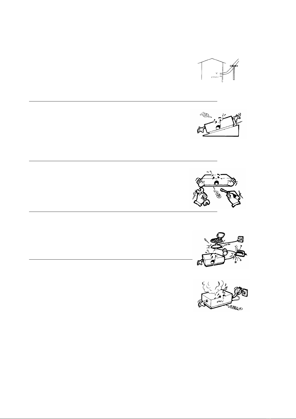
5-D: Unpacking the Unit
Carefully unpack your KRUUSE-SP1 unit and verify that all components and accessories are
included:
(Figure 1) All components and accessories
Item
Quantity
Item
Quantity
(1) Main Unit
1
(2) Foot Control / Foot Switch
1
(3) AC Power Cord Set.
1
(4) PU Water Tubing
1
(5) User Manual & Literature Packet
1
(6)
ART IF-50 Streamline Universal Plastic Handle Internal Flow Insert.
ART P-10 Straight Angle Universal Metal Handle External Flow Insert.
Optional
Optional
(7) Water Hose/ Quick Disconnect Assembly.
Optional
(8) Micro-motor
1
(9) Micro-motor seat
1
(10) Straight Hand piece.
Optional
(11) ProphyAngle
Optional
NOTE:
While unpacking, check your KRUUSE-SP1 unit for any damages. If any damages are
found, please contact your dealer immediately. Enter the unit serial number on your
warranty card and mail it within 14 days from the date of purchase.

- 14 -
5-E: Power Cord / Power Connection
Always make sure that the power switch is set to the OFF position before performing the
following tasks:
oPlug the detachable AC cord into the back of the unit.
oPlug the 3-prong plug into a grounded outlet.
Safety Instructions
A. Grounding:
Prior to connecting accessories to the unit, check that the main unit is plugged into a
grounded wall outlet.
B. Main voltage range and fuse:
Prior to plugging the AC adapter into the power outlet, check that the voltage is supported.
5-F: Foot Control Cable Assembly Connection
Align the pins of the foot control plug with the receptacle on the back of the device and push in
until the plug is firmly seated.
5-G: Water Supply Line Connection
Push the blue water tube (hose) into the stainless steel receptacle until the hose cannot be pushed
any further. Then tighten the screw.
Connect the quick connect to the water supply line. The KRUUSE-SP1 should be prepackaged
with a male quick connect. If a female quick connect is necessary, please contact a Bonart
distributor to purchase it.
Inspect all connections for leaks.
To remove the water line from the KRUUSE-SP1 scaler, first, turn off the water supply or
disconnect the water supply line. Then loosen the screw on the water tube from the receptacle of
the unit and gently pull the water hose out.
5-H: Hand piece Cable Assembly Connection
The KRUUSE-SP1 scaling hand piece is designed only for inserts with a frequency of 25khz. The
KRUUSE-SP1 is no long available in 30khz so please do not try using a 30khz insert with the
KRUUSE-SP1.
- 15 -
5-I: Polishing Hand Piece Assembly and Start Up.
Prophy Angle
Straight Hand Piece
Micro-motor
Knurled Knob
Locking Ring
To assemble the polishing hand piece, connect the Prophy Head, Straight Hand Piece, and
Micro-motor by following the steps below:
1. Connect the straight hand piece and the micro-motor by pushing the straight hand piece over
the rod of the micro-motor. It should snap into place.
2. Attach the prophy angle to the straight hand piece by following the steps below:
A) Unlock the prophy head from the straight hand piece by turning the locking ring clockwise.
This should open the lock. Note: When you first unpack the straight hand piece, there may be
a metal rod at the top that serves as a placeholder. Remove the rod after you open the lock.
B) Match the groove at the base of the prophy head with the top of the straight hand piece and
connect them together.
C) Close the lock by turning the locking ring counter-clockwise. The prophy head should now
be locked onto the straight hand piece and should not fall off during operation.
D) If you wish to remove the prophy head, follow step A to release the lock on the prophy head.
WARNING:The prophy head needs lubrication and cleaning on a regular basis.
When you are ready to begin polishing, follow the steps below:
1. Place a rubber cup on the prophy head and put paste in the cup to begin polishing.
2. Press the Micro-motor (mode) button to switch from scaling to polishing mode
3. Adjust the Oscillating dial to a low speed, 2,000 rpm.
4. Press on the foot switch to engage the polishing hand piece and begin polishing.
5. Add paste as needed.
- 16 -
5-J: Assembling the Scaler Unit
1. Switch the power of the KRUUSE-SP1 off. The power indicator should not be lit if the
machine is off.
2. Plug the power cord of the main unit into a grounded AC power outlet.
3. Install an insert into the hand piece pushing it into the hand piece until it is firmly seated.
4. Check the water tube connection to the water supply source and main unit.
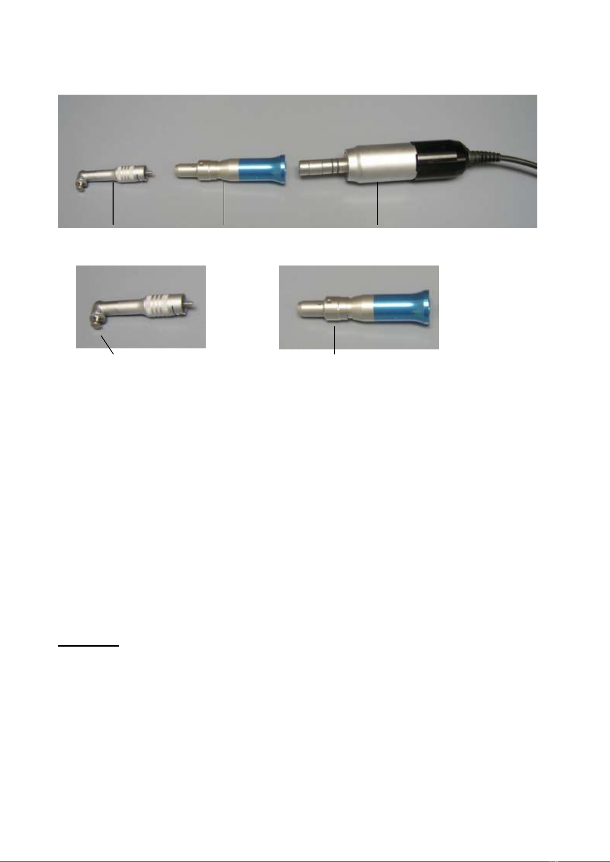
Section VI: General Description and Information of Parts
1. Main unit
5. Water control knob
9. Water hose input
2. Hand piece
6. Power control knob
10. Power cord socket
3. Power button
7. Micro-motor socket
11. Forward/Reverse switch
4. Micro-motor (Mode) button
8. Foot switch socket
Figure 2. KRUUSE-SP1 diagram
1. Main Unit
The main unit generates power and produces a signal that is passed to the hand piece. The
hand piece is then powered up and vibrates the installed insert.
2. Hand piece
The hand piece is the housing for scaling inserts. Inserts are interchangeable and can be
installed with a firm push. To remove the insert, hold the insert at the grip and pull from the
hand piece. Be careful not to cut yourself in the process. Inserts that are compatible with
the KRUUSE-SP1 are made by: Bonart, Dentsply and Hu-Friedy.

- 17 -
The hand piece will heat up when used due to the power generated by the main unit.
Therefore it is necessary to cool the hand piece by ensuring that an adequate amount of water
flows through the hand piece.
CAUTION:Make sure that new insert is firmly seated.
CAUTION: Do not depress the footswitch when there is no insert installed. Doing so
will cause the hand piece to melt!
NOTE:The KRUUSE-SP1 is a stand-alone unit and is now only available in 25Khz.
Please do not use 30Khz inserts with the hand piece.
3. Power button (ON/OFF)
The power button is used to turn the KRUUSE-SP1 main unit on and off. When the power is
on, the LED indicator should be lit. When turned off, the LED power indicator should not be
lit.
Do not depress the foot switch while turning on the KRUUSE-SP1.
4. Micro-motor (Mode) button
The micro-motor (Mode) button is used to switch between polishing and scaling
mode. When pushed, the LED indicator should be lit, indicating that the system
is operating in polishing mode. Under polishing mode, the micro-motor is
engaged. To return to scaling mode, push the button again.
5. Water control knob
The water control knob allows you to control the amount of water that flows through the hand
piece. If turned clockwise, the amount of water will decrease. If turned counter-clockwise,
the amount of water will increase. Please note that water is necessary to cool the tip and
prevent overheating so it is necessary to ensure that an adequate amount of water flows
through the hand piece while operating the device. The larger the water stream, the lower the
temperature, and vice versa.
WARNING:Do not turn the water knob counter-clockwise more than three full turns.
Doing so will damage the internal water line needle.
WARNING:If needed, gently adjust the water control knob to prevent any serious
damages to the water valve.
6. Power control knob
The Power Control Knob allows you to control the power intensity. When turned clockwise,
the power intensity increases. When turned counter-clockwise, the power intensity decreases.

- 18 -
7. Micro-Motor Socket
The micro-motor socket is where you connect the micro-motor to the main unit. It is located
on the back of the main unit at the bottom left.
8. Footswitch Socket
The foot switch socket is where you connect the foot switch to the main unit. It is located
next to the water hose input on the back of the main unit.
9. Water hose input connector
The water hose input connector is the contact point for the water tube and the main water
supply line. Use either a male or female quick connect to connect the water tube to the water
supply. The KRUUSE-SP1 comes with a male quick connect attached to the water tube.
10. Power cord socket
The power cord socket is where you connect the power cord to the main unit.
11. Forward / Reverse switch
The Forward/Reverse switch allows you to control the direction of the micro-motor. It is
located on the back of the main unit.

- 19 -
Section VII: Techniques
7-A: Performing Ultrasonic Scaling Procedures
1. Use purified or distilled water to prevent infection when patients experience tissue
laceration during treatment
2. Keep the power cord tidy to avoid tripping and other accidents.
3. Position the footswitch in an easily accessible spot for the user. Keep the footswitch cord
tidy to avoid tripping and other accidents.
4. Hold the empty hand piece in an up right position when testing to see if the scaler is
working properly. Tap the footswitch until water appears. Do not repeatedly tap or hold
the footswitch down. The empty hand piece will melt!
5. Lubricate the rubber O-ring on the insert with water before placing it into the hand piece.
Install the insert by firmly pushing until seated.
6. Hold the hand piece over a sink or drain with an insert installed. Verify that water is
reaching the tip.
7. Check your scaling inserts for wear and replace as needed.
8. Use your foot to press down on the foot switch to allow water to reach the hand piece.
Release the foot switch to stop the water.
9. Control the amount of water that flows through the hand piece by using the water control
knob. Turn counter-clockwise to increase water flow and clockwise to decrease water
flow.
NOTE:To lower the temperature of the hand piece, increase the water flow.
CAUTION:A continuous flow of water is required to keep the hand piece cool during
use.
Table of contents
Other Bonart Media Converter manuals


Popular Media Converter manuals by other brands


Technica Engineering
Technica Engineering 100BASE-T1 MEDIACONVERTER BCM user manual

Dragino
Dragino RS485-LN user manual

Lenz
Lenz Digital plus LE1835A Information

Data Video
Data Video DAC-60 instruction manual

Blankom
Blankom EMU-4220 Installation and operation instructions

Georges Renault
Georges Renault Desoutter Chicago Pneumatic B14A manual


