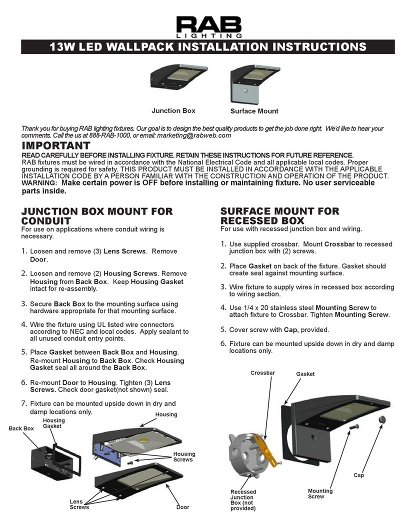
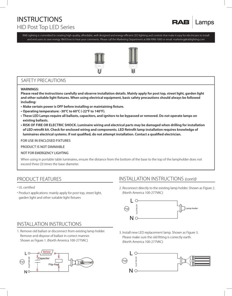
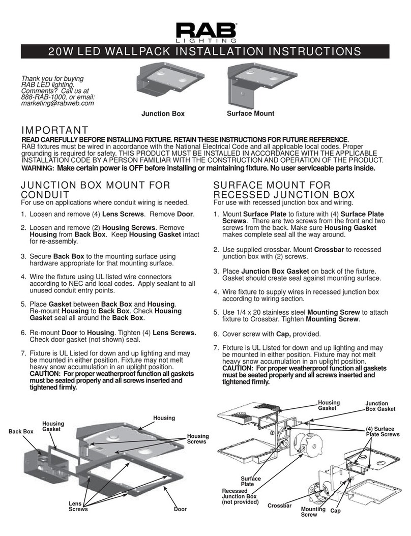
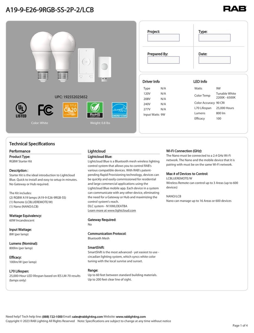
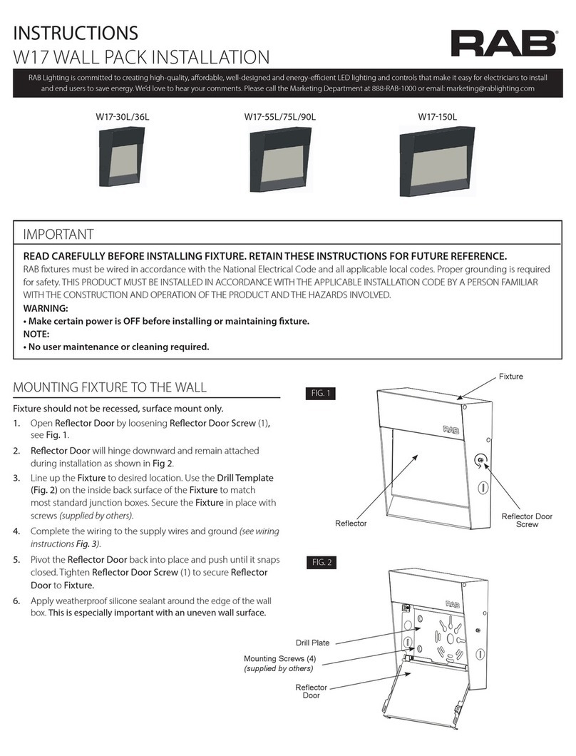
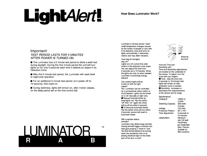
RAB A17 User manual

INSTRUCTIONS
A17™ AREA LIGHT INSTALLATION
A 1 7 S l i p t t e r
A17 Universal Pole
IMPORTANT
READ CAREFULLY BEFORE INSTALLING FIXTURE. RETAIN THESE INSTRUCTIONS FOR FUTURE REFERENCE.
WARNING: Make certain power is OFF before installing or maintaining xture. No user serviceable parts inside.
WARNING: Do not use an electric generator to test LED xtures.
WARNING: Min 75°C SUPPLY CONDUCTORS.
Suitable for wet locations.
1. Remove the Arm CoveArmArm
Cover Screws
Arm.
ArmArm and
tighten securely to housing.
Arm CoverScrews
Arm
Screws
Arm Cover
Arm
FIG. 1 FIG. 2
FIG. 3
FIG. 4
Square Pole Mount
1. Place the Bolster Plate inside the Pole
2. Remove the Round Pole Adaptor Plate.
Arm to Square PoleBolt.
Arm Cover
Pole to connect to the Arm.
enclosure (Fig. 7).
Pole.
Round Pole Mount
1. Place the Bolster Plate inside the Pole
2. Arm to Round Pole Bolt.
3. Arm Cover
4. Pole to connect to the Arm.
enclosure (Fig. 7).
5. Pole.
Pole
Bolster Plate
Bolt
Pole
Arm
Round Pole
Adaptor Plate
Arm Cover
Note: See Pole Drilling Pattern Detail (Fig. 8).

INSTRUCTIONS
A17™ AREA LIGHT INSTALLATION
NOTICE: Adjustable angle is 90°.
1. Place the Sliptter over the Tenon and secure the Fixture
set ScrewsSliptter
Fixture through Sliptter
Sliptter and
Sliptter, loosen the Locking Bolt
Fixture
Sliptter
angle.
Figure 14
Note: These instructions do not cover all details or variations in equipment nor do they
provide for every possible situation during installation, operation or maintenance.
Fig. 7.
lead.
FIG. 5
FIG. 7
FIG. 6
BLACK/BROWNLINE
WHITE/BLUECOMMON
PURPLE(+) DIM V+
PINK
GREEN/YELLOW
(-) DIM V-
GROUND
Locking Bolt
Screws
Tenon
(Fig. 8).
Hole A B, Cor Das needed.
0.625”
0.425”
5 1/2”
3”
2”
1”
A
B
C
D

INSTRUCTIONS
A17™ AREA LIGHT INSTALLATION
CAUTION: Do not open or remove Respirator Plug as shown
in Fig. 9. Be sure xture temperature is cool enough to touch.
Do not clean or maintain while xture is energized.
solution.
RESPIRATOR Plug
Do not open/
Do not remove.
FIG. 9
Easy Answers
rablighting.com
Visit our website for product info
Tech Help Line
Call our experts: 888 722-1000
e-mail
Free Lighting Layouts
Answered online or by request
© 2021 RAB LIGHTING Inc.
RAB WARRANTY: RAB’s warranty is subject to all terms and conditions found at rablighting.com/warranty
73712-RAB
A17-70-375W - IN - 1022
1.
2.

Microwave Motion Sensor
Page 1.
PERFORMANCE
Operating voltage 12 ± 2V DC
Operating current 30mA
Output DIM 0-10V
Stand-by power <0.5W
Brightness 70%/80%/90%/100%
Detection area 20%/50%/75%/100%
Hold time 10s/1min/10min/30min
Daylight threshold 10Lux/30Lux/50Lux/100Lux/Disable
Stand-by period 1min/30min/60min/+∞
Stand-by dimming level 10%/20%/30%/50%
Microwave frequency 5.8GHz ± 75MHz
Microwave power <0.5mW
Detection angle 30-150°
Control line Black/White:12V+ ; Purple: DIM+ ; Pink: 12V-/DIM-
Mounting height Max 15M (ceiling mounted)
Detection range Max Ø15m (ceiling mounted) Max 20m(wall mounted)
Operating temperature -25°C~+60°C
IP rating IP65
OPTIONAL REMOTE
Not Included (Order REMOTE-OD)
MVS-OD SENSOR
RoHS IP RATING
10-15M FIXTURE
ALTITUDE

Microwave Motion Sensor
Page 2.
.
DIMENSIONS
2 1/4"
4"
Weight: 0.14lb
Ceiling Mounted
Mounting Mounting
Height
Covered
Well Covered
Wall Mounted
Lux o
Lux on
Natural light
light on automatically
light o automatically
10 8 6 4 2 2 4 6 8 10
2
4
6
10
12
14
16
8
18
2 4 6 8 10 12 14 16 18
4
3
2
1
1
2
3
4
DETECTION COVERAGE
L
N
Pink
Purple
Black/White: 12V+
LED Driver
LED Driver
Black/White
Purple: DIM+
Pink: 12V-/DIM-
WIRING DIAGRAM
Height
MVS SENSOR FACTORY SETTINGS
BRIGHTNESS
100%
HOLD TIME 1 Minute
DAYLIGHT Disabled
SENSITIVITY 50%
STAND-BY DIMMING LEVEL 20%
STAND-BY TIME 1 Minute

Microwave Motion Sensor
LUX ON-OFF
Ceiling Mounted
Mounting Mounting
Height
Covered
Well Covered
Wall Mounted
Lux o
Lux on
Natural light
light on automatically
light o automatically
10 8 6 4 2 2 4 6 8 10
2
4
6
10
12
14
16
8
18
2 4 6 8 10 12 14 16 18
4
3
2
1
1
2
3
4
Sensor automatically turns o light when ambient brightness exceeds preset lux level. Following preconditions apply to use the Lux On-
O function:
• Stand-by period : +∞
• Stand-by dimming level : 10%, 20%, 30% or 50%
• Daylight threshold : 10Lux, 30Lux, 50Lux or 100Lux
When ambient brightness
is lower than preset lux
level, light automatically
turns on
When ambient brightness
is higher than preset lux
level, light automatically
turns o
Light dims to stand-by
level when there is no
motion detection after
hold time
When motion detected
while ambient brightness is
insucient, light DIMs 100%
ORIGINAL/COMPETITION
RAB VERSION IN COLOR
RAB VERSION IN GREYSCALE
Page 3.
.

PROGRAMMING GUIDELINES
INSTRUCTIONS
REMOTE CONTROL - IN - 0322
73724-RAB
1. If you want to send a setting, it will only work if the remote control is on. If you do not
press any button within 10 seconds, the indicator light will go out.
2. When using “ON/OFF”button, the rest of the buttons except the “ON/OFF”,
3. When using “TEST” button, the rest of the buttons except the“TEST”, “SENSITIVITY” and
4.
5.
with the measured power.
Easy Answers
rablighting.com
Visit our website for product info
Tech Help Line
Call our experts: 888 722-1000
e-mail
Free Lighting Layouts
Answered online or by request
© 2022 RAB LIGHTING Inc.
ON/OFF (Long press the“ON/OFF” button until the brightness indicator light is on (First-row).
BRIGHTNESS
Note: MVS Sensor Brightness factory setting is 100%.
Note: MVS Sensor factory setting hold time is 1 minute.
10lx/30lx/50lx/100lx.) Note: MVS Sensor daylight threshhold factory setting is disabled.
SENSITIVITY
Note: MVS Sensor sensitivity factory setting is 50%.
Note: MVS Sensor standby dimming level factory setting is 20%
∞ / 1min, 30min, 60min).
∞
100/200 lux; or
< preset lux and motion is detected,
light will turn on at present lux).
note: MVS Sensor standby dimming level factory setting is 1 minute.
RESET
∞.
TEST The button “TEST” is for testing purpose after debugging. Pressing this button, the sensor goes to test
mode (hold time is only 3s).
Button Setting Area
BRIGHTNESS100%)
(10lx/30lx/50l/100lx)
(10S/1min/10min/30min)
SENSITIVITY
∞/1min/30min/60min)
TEST
SEND
ON/
OFF
+
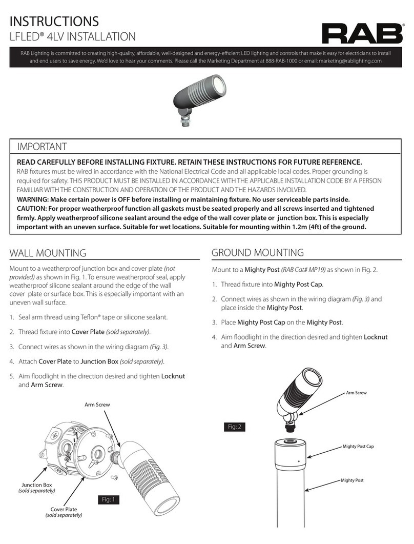
This manual suits for next models
2
Table of contents
Other RAB Outdoor Light manuals

RAB
RAB WPLED20 User manual

RAB
RAB LUMINATOR LightAlert! LU300 User manual

RAB
RAB HID Post Top LED Series User manual

RAB
RAB W17-30L User manual

RAB
RAB Lightcloud ST19 User manual

RAB
RAB A19-9-E26-9RGB-SS-2P-2/LCB User manual

RAB
RAB LFLED 4LV User manual

RAB
RAB GoodNight Light User manual

RAB
RAB WPLED13N User manual
Popular Outdoor Light manuals by other brands

Intermatic
Intermatic Malibu LT13 instructions

Vaxcel
Vaxcel T0442 Assembly and installation instructions

BEGA
BEGA 77 589 Installation and technical information

LIGMAN
LIGMAN DU-70127-2 installation manual

Quoizel
Quoizel Newbury NY8316Z Assembly instruction sheet

Hubbardton Forge
Hubbardton Forge 345615 Assembly/installation instructions