Rabe 230 User manual

Flail Mower
Chopper 230, 250, 280
Operating Instructions
Serial-No.
Order-No. 9900.01.40GB01

1. Intended purpose
The Chopper mulcher is designed exclusively for working on fallow land, disused land and grazing and meadow
land. It can also be used for the mulching of green manure, maize, sunflowers and crop residues.
Any use for a purpose other than or exceeding this description shall be regarded as incorrect operation. The
manufacturer will accept no liability whatsoever for resulting loss or damage in these circumstances. The user
bears sole responsibility in these circumstances.
The definition of “use for intended purpose” also covers observance of the specified operating, maintenance and
servicing instructions, along with the exclusive use of original RABE spare parts.
Ensure that all relevant accident prevention regulations are observed, along with generally accepted safety
procedures, health and safety regulations and road traffic laws. Ensure also that the safety instructions on the
stickers attached to the machine are closely followed.
The manufacturer will accept no liability whatsoever for loss or damage caused by the carrying out of unauthorised
modifications to the machine.
Carefully read through the operating instructions BEFORE starting up the machine for the first time!
Please ensure that this manual is handed over to the new owner if the machine is sold or otherwise
disposed of.
KEY TO SYMBOLS
Important note
Technical note
Safety precaution
Mulchers are designed for intensive use in the care of fallow land, disused land and grazing and meadow land.
They can also be used for the mulching of green manure, maize, sunflowers and crop residues.
1.1 Warranty cover
The buyer’s rights under the terms of the warranty can only be exercised if the corresponding conditions have been
observed.
All claims must be submitted to the manufacturer in writing.
The manufacturer shall bear no liability if interim repairs have been carried out by the user without the
consent of the RABE company, nor for any loss or damage resulting from the installation of items other
than genuine original spare parts.
Please observe the operating instructions contained in this manual.
Failure to use the machine for its intended purpose will void all liability on the part of the manufacturer.
Examine the machine upon delivery and check it for signs of transport damage or missing items. Note that all
claims must be submitted to the manufacturer in writing within eight (8) days.

The warranty will also be voided in the following circumstances:
•If the user commits an error while manoeuvring the machine
•If damage is due to insufficient maintenance
•If interim repairs have been carried out by the user without the consent of the RABE company, and if loss
or damage results from the installation of items other than genuine original spare parts
•If the user has failed to observe the operating instructions contained in this manual
•If the permitted performance limits have been exceeded (see table 1 in the section entitled “Technical
data”).
1.2 Machine identification plate
Each implement is fitted with a machine identification plate (fig. 1.) containing the following data:
Designation (mulching implement)
Company name and address of the manufacturer
Type
Weight in kg
Year of construction
These data must accompany all technical enquiries or orders for spare parts.
Fig. 1

2. Technical data
Fig.
2
1. Housing
2. Transmission
3. V-belt
4. Hook trestle - 3FS
5. Roller
6. Three-point linkage
7. Slide
8. Slide bars
2.1 Noise prevention
The implement operates at a noise level of 70 – 90 dB. Noise is a
particular hazard when the rear window of the tractor is open. We
therefore strongly recommend the use of hearing protection.
2.2 Options
Depending on the operating conditions, the following cutting implements
can be used:
•Optional Y-blades (for stalks/trunks of up to 3 cm in diameter)
•Standard bootee flails (for stalks/trunks of up to 5 cm in diameter)
The maximum diameter of the items being cut depends on the type
and strength of their stalks and trunks. Note that the data given here
correspond to the trunks and stalks of living plants.
The crosscut blade option improves performance, allowing the
mulched material to be broken up into smaller fragments.
3
8
7
2
1
6
5
4

2.3 Technical specifications
Table 1
Type Chopper
230 Chopper
250 Chopper
280
Operating width cm 216 232 265
Min. towing capacity PS 55-60 65-75 75-85
Power take-off shaft rpm 540/1000 540/1000 540/1000
Y-blades Number 78 84 96
Bootee flails Number 26 28 32
Weight kg 695 730 780
Lateral displacement cm 500 500 500
Three-point linkage Cat. II. II. II.
Width mm 2510 2670 3000
Length mm 1010 1010 1010
Height mm 1050 1050 1050
Rotor turning speed rpm 2243 2243 2243
3. Safety measures
3.1 General safety and accident prevention regulations
1. Please observe the points on safety and accident prevention, in addition
to the general instructions contained in this manual.
2. The warning and indication signs attached to the implement contain
important instructions on how to operate it safely. Prevent danger by
observing them at all times.
3. Be sure to observe all relevant traffic laws when using public roads.
4. Familiarise yourself with all devices, control elements and their respective
functions BEFORE starting work. DO NOT wait until the implement is
already in operation.
5. Machine operators should wear tight-fitting clothing. Do not wear loose or
hanging items of any kind.
6. Keeping the machine clean will reduce the danger of fire.
7. You are recommended to use a tractor fitted with a safety cab.
8. Check the area of operation carefully (watch out for children) BEFORE
starting up or carrying out any manoeuvres. Ensure that you have an
adequate field of vision at all times.
9. Passengers MUST NOT ride on the tractor or implement while it is being
operated or towed. The implement must not be used as a load-carrying
trailer.

10. Hitch the implement up as instructed, and connect it only to the specified
devices.
11. Observe the maximum permitted axle loads of the tractor (see vehicle
documentation).
12. Keep to the limits regarding maximum external trailer dimensions
(German StVZO traffic regulations or your local equivalent).
13. Ensure that regulation towing equipment, such as lights, warning triangles
and additional safety devices, is attached and in full working order.
14. The release cables of the quick-action couplings should hang loosely, and
must not trip of their own accord when the implement is lowered.
15. NEVER leave the driver’s seat while the vehicle is in operation.
16. Note that towed implements and the use of ballast weights affect driving
performance, steering and braking.
You should take this into account when estimating turning circles and
braking distances.
17. Take into account the overhang dimensions and centrifugal mass of the
towed implement when driving into bends. Secure the lower arm of the
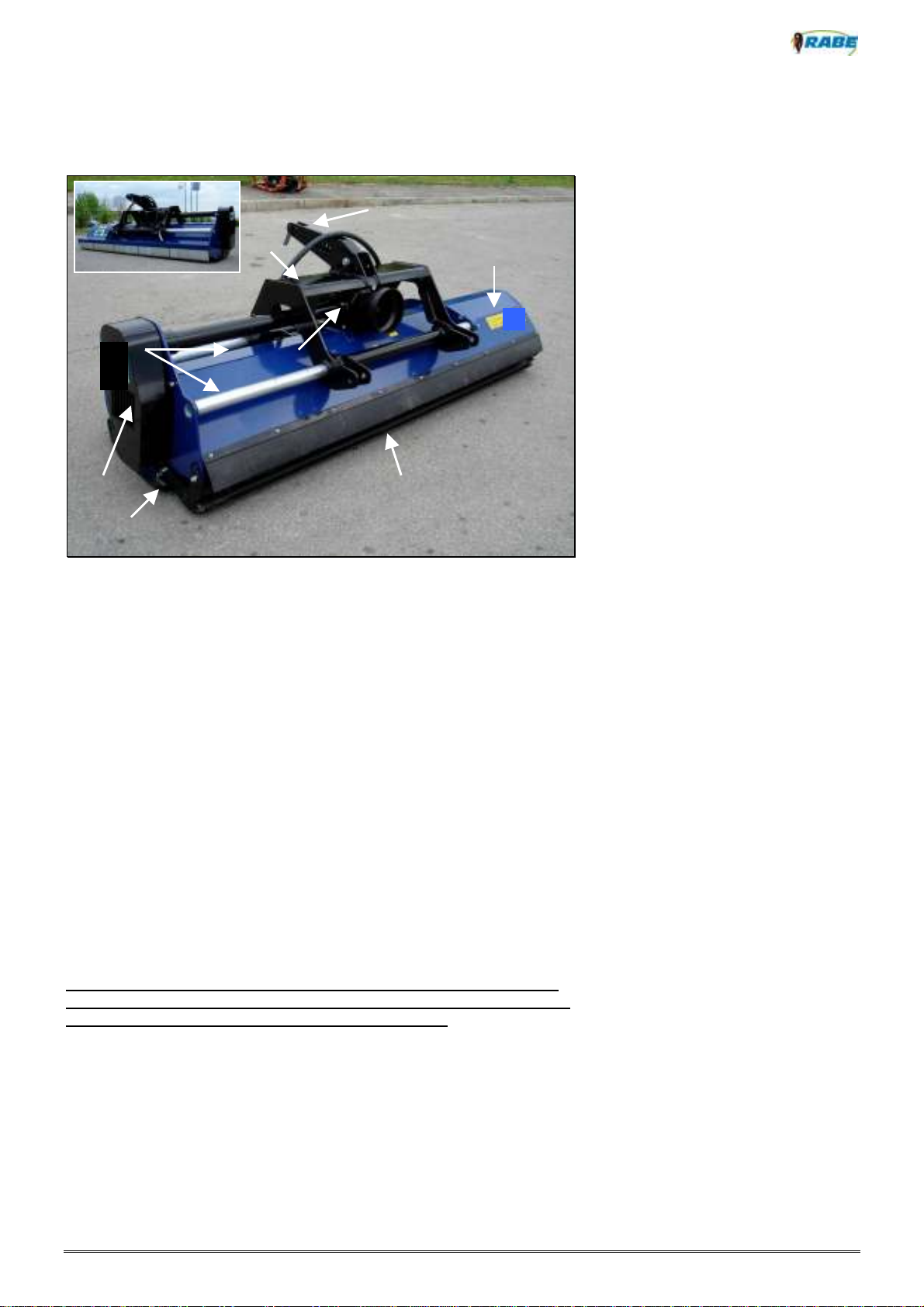
three-point hydraulic linkage to stop the implement rocking back and forth.
18. Ensure that all safety devices are attached and in full working order
BEFORE you operate the implement.
19. DO NOT remain within the turning circle or operating area of the
implement. Beware of flying fragments of stone and vegetable matter.
Before activating the unit, ensure that no one is standing within the
ejection range of the mulcher . Keep away from rotating machine parts.
20. DO NOT remain within the turning or pivoting range of the implement.
21. Beware of the danger of crushing and cutting from components run from
external power sources (e.g. hydraulic items).
22. Before leaving the tractor unattended, lower the implement to the ground,
switch off the engine and remove the ignition key.
23. DO NOT walk between the tractor and implement without first applying
the handbrake and/or chocking the wheels to stop the outfit rolling away.
3.2 Towed implements and their transport
1. Adjust the operating controls accordingly before coupling or
uncoupling implements via the three-point linkage.
2. Before hitching up via the three-point linkage, ensure that the
tractor and implement are fully compatible with one another.

3. Note that there is a danger of crushing and cutting injuries occurring in the
area of the three-point linkage.
4. DO NOT pass between the tractor and implement once the three-point
linkage has been connected to the vehicle mounted controls.
5. Always ensure, when the implement is raised for towing, that the tractor’s
three-point linkage is adequately secured at the sides.
6. Before driving the outfit on the road, ensure that the operating lever is
secured to stop the implement being lowered by accident.
7. Hitch up and connect implements in accordance with regulations. Check
the trailer braking system for correct functioning. Observe the
manufacturer’s instructions.
8. Working implements should only be towed and operated using tractors
designed for the purpose,

3.3 Operation from the power take-off shaft
1. All power take-off shafts must be fitted with the regulation protection and
safety devices specified by the manufacturer.
2. The protective tube and cowling fitted to the drive shaft and the guard on
the power take-off shaft must be correctly fitted and in full working order
at both ends.
3. Ensure that drive shafts are fitted with the specified tube protectors for
towing and operation. (See the operating instructions provided by the
supplier of the drive shaft).
4. Before attaching or removing the drive shaft, disengage the power take-
off shaft, switch off the engine and remove the ignition key.
5. Ensure that the drive shaft is correctly fitted and secured at all times.
6. Attach chains to stop the drive shaft guards rotating at the same time.
7. Before engaging the power take-off shaft, ensure that the turning speed
selected at the tractor is within the maximum permitted turning speed limit
(operating speed) of the shaft. A turning speed of 540 rpm is normal for
the power take-off shaft (see table of settings).
8. Gentle handling of the coupling elements will help ensure a long service
life for both the tractor and the mulching implement.
9. Clear the area of bystanders before engaging the power take-off shaft.
10. NEVER engage the power take-off shaft with the engine stopped.
11. Keep away from the rotating power take-off and drive shafts during
operation.
12. Always disengage the power take-off shaft if the angle of tilt is excessive,
or if it is no longer required. Disengage the power take-off shaft as soon
as the shutoff valves are closed.
13. IMPORTANT! Beware of continued running due to remaining momentum
after disengaging the power take-off shaft. Keep away until the
mechanism has come to a complete stop. And then wait before
attempting to carry out further work of any kind.
14. Always disengage the power take-off shaft, switch off the engine and
remove the ignition key BEFORE cleaning, lubricating or adjusting any
shaft-driven item.
15. Place the disconnected drive shaft in the support rest provided.
16. After detaching the drive shaft, fit the protective cover to the shaft end.
17. Repair any damage before working with the implement.
1.

3.4 Hydraulic system
1. Note that the hydraulic system operates at high pressure.
2. Ensure that the hydraulic hoses are connected as specified before
operating the hydraulic cylinders and motors.
Release pressure at both the tractor and implement end before
connecting the hoses to the tractor’s hydraulic system.
3. The hydraulic function plugs and sockets used to connect the tractor
and implement should be clearly marked to prevent incorrect
connection. Accidental swapping of connections may lead, for
example, to the implement being lowered when it should be raised.
Danger of accident!
4. Check the hydraulic hoses regularly and replace at the first sign of
wear or ageing. Ensure that the replacement hoses conform to the
technical requirements of the implement manufacturer.
5. Prevent possible injury. Always use appropriate detection equipment
when checking for leaks.
6. Pressurised fluids (hydraulic oil) are apt to escape without warning,
possibly resulting in skin penetration and serious injury. Seek
immediate medical help if an injury does occur, as there is a danger
of infection.
7. Before working on the hydraulic system, lower the device, release
the hydraulic pressure and switch off the engine.
8. The hose conduits should not be used for any longer than six years
(including up to two years’ storage time). Hose conduits are subject
to natural ageing, even if stored correctly and subjected only to
permitted loads. This is why their storage and service life is limited
You should determine, on the basis of experience and given the
potential danger of accidents, if actual operating conditions make
shorter replacement intervals advisable. Note that different
conditions may apply to hoses made of thermoplastic material.
9. Dispose of waste oil and lubricants correctly.

3.5 General safety and accident prevention regulations
1. You should normally disengage the drive mechanism and switch off the
engine before carrying out maintenance, servicing or cleaning work of any
kind, or before attempting repairs. Always remove the ignition key.
2. Check all screws and nuts at regular intervals for correct tightness, and
retighten as required.
3. Insert adequate props and/or axle stands before working on the raised
implement.
4. Dispose of waste oil, lubricants and filters correctly.
5. Disconnect the tractor’s alternator and battery before carrying out
electrical welding work on the tractor or attached implement.
6. All spare parts must conform to the implement manufacturer’s minimum
technical requirements. This is guaranteed by the exclusive use of
ORIGINAL GENUINE PARTS.

3.6 Safety devices
Fig. 3
1. Drive shaft guard
2. V-belt guard
3. Safety stickers
4. Protective flaps
5. Protective rubber skirt
4. Description and function of the implement
In the standard configuration, the rotor shaft is fitted with bootee flails (fig.
5) designed for heavy-duty operating conditions (stalks/trunks of up to 5
cm in diameter). Optional Y-blades (fig. 4) are available for lighter
mulching tasks (stalks/trunks of up to 3 cm). The rotor shaft turns in the
opposite direction to the direction of travel at a rate of 2,243 rpm. The
implement is operated via the drive shaft, transmission and belt-drive
system. The cutting tool attachments clear away the vegetable matter
and feed it into the lower housing for (optional) further processing with the
crosscut blades, which break the material up into smaller fragments. The
mulched material is deposited at the back of the implement.
Fig. 4
3
2
1
4
3
5
Fig.5

Fig.6
5. Transport and attachment
5.1 Transporting and unloading
The machine should be unloaded with great care, using lifting equipment
designed to handle an object of its size and weight.
Do not allow the implement to knock against neighbouring objects, and
do not perform any other action that is likely to damage it.
Examine the machine carefully for signs of transit damage.
Check that all screws and nuts are correctly tightened. Check that screws
and bolts in the cutting area of blade attachments are free of damage and
correctly attached, and also that the tool attachments are free to rotate
without touching these screws and bolts.
5.2 Coupling and uncoupling the implement
Before coupling, check:
•that the implement is in full working order
•that all safety devices are in their correct positions
•that all cutting tool attachments fitted to the rotor shaft are in full
working order
•that grease has been applied at all lubrication points, and that the
level of the transmission oil is correct
•that the V-belts are correctly tensioned
•that the coupling rating and turning speed (540 or 1,000 rpm) and
drive direction of the tractor and implement are compatible and
that they match accordingly
Reverse the tractor up to the implement. Secure the lower arm of the
tractor to the lower-arm bolt and insert the linch pin. Secure the upper
arm and insert the stop pin. Adjust the upper arm so that the implement is
horizontal to the ground surface.
When the implement is raised, there should be only minimum play on the
lower arms of the tractor. This is to stop the machine swaying back and
forth during operation.

Secure the lower arms of the tractor with stabilising struts or chains.
The same procedure applies to FRONT END attachment.
Once the machine has been attached, connect the hydraulic hoses to the
tractor and check them for correct functioning.
Attach the hook trestle in such a way that the implement is
horizontal to the tractor.
The trestle attachment permits both rear- and front-end coupling of the
machine. Once the machine has been attached, carefully adjust the
connecting bolt (fig. 7.).
If you change from rear- to front-end attachment, always
check to ensure that the drive direction of the tractor still coincides
with that of the implement, and that the turning speed of the power
take-off shaft is correct.
Fig. 7
5.3 Fitting and adjusting the drive shaft
Before connecting the drive shaft to the input shaft, clean the drive input
shaft on the machine and grease the drive shaft. Before using the drive
shaft for the first time, ensure that it is compatible with the tractor. As the
adjustment procedure only applies to this type of tractor, the procedure
must be checked and, if necessary, repeated whenever a different tractor
is used.
Whenever you fit a new drive shaft element to the power-take off point on
the tractor for the first time, do so without connecting the drive shaft tubes
to each other. When the drive shaft tubes are pushed together, they must
not collide with the forks of the universal joint. A minimum safety distance
of 4-5 cm must be maintained. To adjust to the correct length, hold the
two sections of drive shaft next to one another in the shortest operating
position and mark their positions. Shorten the inner and outer protective
tubes by the same amount. Shorten the inner and outer push-in profiles
by the same length as the protective tube. Smooth down the cut edges
with a file and carefully remove all swarf and other debris. Grease the
push-in profiles before inserting them into each other.
Note that an excessively long drive shaft can cause
damage to both the tractor and the implement.
Attach the drive shaft to the implement and tractor,
along with the complete drive shaft assembly and guard
extension.
2
1

Fig.8
: Length of the drive shaft with the implement lowered
Fig.9:
Length of the drive shaft with the implement in its horizontal
position
5.4 Tractor stability
Depending on the size of the tractor, the load on its front axle
will be relieved to some degree or other as the implement is
raised. Ensure that the tractor’s specified front axle load
(20% of tractor weight) is maintained.
Fig. 10
1/3 cevi

6. Adjustment settings
6.1 Adjustment of the cutting height
The cutting height adjustment depends on the vegetable matter being
handled. The cutting height is regulated by the tractor’s hydraulic system.
Ensure that the implement is raised at least 1-3 cm off the ground (fig.
11), and that it runs on its roller. The roller must be adjusted if the cutting
height is to be increased.
(Fig. 12).
Fig. 11 Fig. 12
Neither the tool attachments nor slides must not touch
the ground. The slides are fitted only for protection
purposes. The implement actually runs on the roller.
6.2 Lateral displacement adjustment
Lateral displacement is adjusted using the hydraulic cylinder (fig. 13.).
The maximum displacement is 50 cm.
Fig. 13
1-3 cm

6.3 V-belt tension
Correct adjustment of the V-belt will ensure optimum operation of the
implement and a long service life for the belt.
See description of V-belt tension on page 28 of this manual.
Fig. 14
Always disengage the power take-off shaft, switch off
the engine and remove the ignition key before
tensioning the V-belt.
The V-belt is normally correctly tensioned if a force of
100 N (10 kg weight) results in around 1.5 cm of play
when applied at the mid-point of the belt.

7. Initial startup
Examine the ground surface before starting up the
machine. Fields in a fallow state may be strewn with
stones, rocks, tree stumps, large branches and similar
objects.
Observe the drive shaft turning speed of the implement.
The limit is 540 rpm; the ideal speed 1,000 rpm.
Fig. 15
The operating speed of the implement depends on the vegetable matter
being cut. The ideal operating speed is 3-8 km/h.
Fig. 16
NEVER reverse with the implement in its operating position
(fig. 16). This can result in damage to the machine components
.
Always raise the implement into its transport position
when turning.

8. After work
At the end of each shift, disengage the power take-off shaft and raise the
implement into its transport position. The implement can now be towed
away.
Adapt your driving speed to the conditions of the towing
route. Take the lateral overhang and swaying motion of the
implement into account. Prevent damage to the implement: keep
vibration to a minimum
.
Disengage the power take-off shaft for towing.
When uncoupling the implement, observe the safety
precautions listed on page 10 under “Coupling”.
Always park the implement on a dry and even surface after use. We
recommend that you rest it on wooden supports.
8.1 Maintenance
Rinse the implement down with water after use, dry it, apply grease (to
prevent rust) and park it under cover. If you use a high-pressure hose,
take care to avoid the bearings, hydraulic components and similar items.
High-pressure cleaning can damage these parts of the implement.
Fig. 17

9. Caring for the implement
Before carrying out cleaning, maintenance or repair work on
the implement, ensure that it is uncoupled from the tractor. Park the
implement on an even, firm, non-slip surface.
The maintenance intervals indicated correspond to normal
operating conditions. If the implement is subjected to heavier
use, these intervals should be reduced accordingly.
Keep the lubrication points clean at all times.
Once maintenance and servicing work is complete, ensure
that all safety devices are refitted.
9.1 Checking the transmission oil level
Always use the same type of lubricant for transmission oil changes (SAE
90).
To change the oil, proceed as follows:
- Unscrew the plug at the bottom of the transmission unit (fig. 18,
item. 1) and let the oil drain out. Use suitable containers for this
purpose. Screw the plug back in.
- Now unscrew the second plug on the transmission unit (fig. 18,
item. 2), rotate the axle shaft (fig. 19 item 4) and pour in about 3
litres of oil, using a funnel.
The oil level should come up the plug (fig. 18, item. 3) on the
transmission unit (located under the transmission guard – it
should be removed for checking purposes) and up to the plug on
the axle shaft (fig. 19, item 5)
Fig. 18
1
2
4
5
3

9.2 Lubrication points
Carefully read through the operating instructions before
applying lubricant.
Lubrication nipples on the implement:
• Running roller bearing – left (fig. 20/2) 1 x
• Running roller bearing – right (fig. 21/3) 1 x
• Rotor shaft bearing – left (fig. 20/1) 1 x
• Rotor shaft bearing – right (fig. 21/4) 1 x
Fig. 20 Fig. 21
Always wear protective gloves when greasing the
implement, and wash your hands thoroughly afterwards.
Use a high-grade lubricating grease (LIS 3).
3
2
1
4
5
This manual suits for next models
2
Table of contents
Popular Food Processor manuals by other brands

PEPCOOK
PEPCOOK 17477031 instruction manual

Hamilton Beach
Hamilton Beach Big Mouth 70570C user manual

Scarlett
Scarlett SC-HB42F25 instruction manual

Krups
Krups i-Coach Touch manual

Cuisinart
Cuisinart EVOLUTIONX CORDLESS RMC-100C Instruction/recipe booklet

BLACK DECKER
BLACK DECKER FP3300SKT use and care manual